Table of Contents
Advertisement
Advertisement
Table of Contents
Troubleshooting

Related Manuals for Daikin VRV R-407C PLUS Series


Summary of Contents for Daikin VRV R-407C PLUS Series
- Page 1 SiE 00-07 Service Manual System R-407C PLUS Series...
-
Page 2: Table Of Contents
SiE 00-07 Inverter K Series R-407C PLUS Series 1. Introduction .....................v 1.1 Safety Cautions ..................v 1.2 PREFACE....................ix Part 1 General Information R-407C PLUS Series ......1 1. Product Outline ..................2 1.1 Year 2000 Models Using New Refrigerant ..........2 1.2 Outline of New Series Products............... 3 1.3 Model Configuration and Combination ............ - Page 3 SiE 00-07 4. Outline of Control (Indoor Unit) .............69 4.1 Drain Pump Control ................69 4.2 Louver Control for Preventing Ceiling Dirt ..........71 4.3 Thermostat Sensor in Remote Controller ..........72 4.4 Freeze Prevention ................. 74 Part 4 Test Operation R-407C PLUS Series........75 1.
- Page 4 SiE 00-07 3.15 Outdoor Unit: Actuation of High Pressure Switch........ 137 3.16 Outdoor Unit: Actuation of Low Pressure Sensor........ 138 3.17 Outdoor Unit: Malfunction of Moving Part of Electronic Expansion Valve (Y1E)....... 139 3.18 Outdoor Unit: Abnormal Discharge Pipe Temperature......140 3.19 Outdoor Unit: Malfunction of Thermistor for Outdoor Air (R1T)...
- Page 5 SiE 00-07 7. Troubleshooting (OP: Schedule Timer)..........171 7.1 Malfunction of Transmission Between Central Remote Controller and Indoor Unit ......171 7.2 PC Board Defect.................. 172 7.3 Malfunction of Transmission Between Optional Controllers for Centralized Control......172 7.4 Improper Combination of Optional Controllers for Centralized Control.................
-
Page 6: Introduction
SiE 00-07 Introduction 1. Introduction Safety Cautions Cautions and Be sure to read the following safety cautions before conducting repair work. Warnings The caution items are classified into “ Warning ” and “ Caution ”. The “ Warning ” items are especially important since they can lead to death or serious injury if they are not followed closely. - Page 7 Introduction SiE 00-07 Caution Do not repair the electrical components with wet hands. Working on the equipment with wet hands can cause an electrical shock. Do not clean the air conditioner by splashing water. Washing the unit with water can cause an electrical shock. Be sure to provide the grounding when repairing the equipment in a humid or wet place, to avoid electrical shocks.
- Page 8 SiE 00-07 Introduction Warning When connecting the cable between the indoor and outdoor units, make sure that the terminal cover does not lift off or dismount because of the cable. If the cover is not mounted properly, the terminal connection section can cause an electrical shock, excessive heat generation or fire.
- Page 9 Introduction SiE 00-07 Caution If the installation platform or frame has corroded, replace it. Corroded installation platform or frame can cause the unit to fall, resulting in injury. Check the grounding, and repair it if the equipment is not properly grounded. Improper grounding can cause an electrical shock.
-
Page 10: Preface
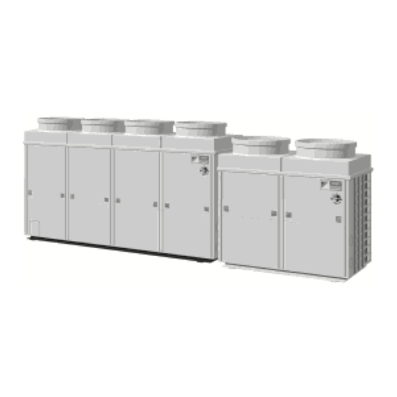
This is the new service manual for Daikin's Year 2000 R-407C VRV PLUS series. Daikin offers a wide range of models to respond to building and office air conditioning needs. We are confident that customers will be able to find the models that best suit their needs. - Page 11 Introduction SiE 00-07...
-
Page 12: Part 1 General Information R-407C Plus Series
SiE 00-07 Part 1 General Information R-407C PLUS Series 1. Product Outline ..................2 1.1 Year 2000 Models Using New Refrigerant ..........2 1.2 Outline of New Series Products............... 3 1.3 Model Configuration and Combination ............ 5 General Information R-407C PLUS Series... -
Page 13: Product Outline
Product Outline SiE 00-07 1. Product Outline Year 2000 Models Using New Refrigerant Outdoor Unit Series New model Equivalent horsepower (HP) Series name R-407C VRV PLUS series Indoor Unit Series New model Model change Continued model Type Type Type Type Type Type Type... -
Page 14: Outline Of New Series Products
SiE 00-07 Product Outline Outline of New Series Products In addition to the use of a new refrigerant (R-407C), the new series products incorporate a function-unit-less structure for significantly improved flexibility and ease of installation. System outline Standard series General name RSXYP~KJY1 Master unit name RXYP~KJY1... - Page 15 Product Outline SiE 00-07 Feature (3) Reduction of installation area 20HP 30HP Conventional system 11.6%reduction 13.7%reduction Function-unit-less system (V0803) Simpler piping work at installation sites 20HP 30HP 14 joints → 6 joints 20 joints → 6 joints Pipe connecting locations Other versatile functions are Long refrigerant piping : equivalent...
-
Page 16: Model Configuration And Combination
SiE 00-07 Product Outline Model Configuration and Combination Number of units and capacity of connectable indoor units Standard Equivalent output 16HP 18HP 20HP 24HP series R-407C VRV PLUS series system model RSXYP16KJ RSXYP18KJ RSXYP20KJ RSXYP24KJ Outdoor unit combination Main unit RXYP8KJ RXYP10KJ RXYP10KJ... - Page 17 Product Outline SiE 00-07 General Information R-407C PLUS Series...
-
Page 18: Part 2 Specifications R-407C Plus Series
SiE 00-07 Part 2 Specifications R-407C PLUS Series 1. Specifications ..................8 1.1 Outdoor Unit .................... 8 1.2 Indoor Unit ..................... 12 Specifications R-407C PLUS Series... -
Page 19: Specifications
Specifications SiE 00-07 1. Specifications Outdoor Unit Model RSXYP16KJY1 RSXYP18KJY1 Constituent Model (Main Unit + Sub Unit) RXYP8KJY1+RXEP8KJY1 RXYP10KJY1+RXEP8KJY1 Power Supply 3 phase 50Hz 380-415V 3 phase 50Hz 380-415V 1 Cooling Capacity 43.8 49.3 2 Heating Capacity 43.8 49.3 Cacing Color Ivory white (5Y7.5/1) Ivory white (5Y7.5/1) Dimensions : (H×W×D) - Page 20 SiE 00-07 Specifications Model RSXYP20KJY1 RSXYP24KJY1 Constituent Model (Main Unit + Sub Unit) RXYP10KJY1+RXEP10KJY1 RXYP16KJY1+RXEP8KJY1 Power Supply 3 phase 50Hz 380-415V 3 phase 50Hz 380-415V 1 Cooling Capacity 54.7 65.7 2 Heating Capacity 54.7 65.7 Cacing Color Ivory white (5Y7.5/1) Ivory white (5Y7.5/1) Dimensions : (H×W×D) (1,440×1,280×690)+(1,440×1,280×690)
- Page 21 Specifications SiE 00-07 Model RSXYP26KJY1 RSXYP28KJY1 Constituent Model (Main Unit + Sub Unit) RXYP16KJY1+RXEP10KJY1 RXYP20KJY1+RXEP8KJY1 Power Supply 3 phase 50Hz 380-415V 3 phase 50Hz 380-415V 1 Cooling Capacity 71.2 76.1 2 Heating Capacity 71.2 76.1 Cacing Color Ivory white (5Y7.5/1) Ivory white (5Y7.5/1) Dimensions : (H×W×D) (1,450×2,580×690)+(1,440×1,280×690)
- Page 22 SiE 00-07 Specifications RSXYP30KJY1 Model Constituent Model (Main Unit + Sub Unit) RXYP20KJY1+RXEP10KJY1 Power Supply 3 phase 50Hz 380-415V 1 Cooling Capacity 82.1 2 Heating Capacity 82.1 Cacing Color Ivory white (5Y7.5/1) Dimensions : (H×W×D) (1,450×2,580×690)+(1,440×1,280×690) Heat Exchanger Cross fin coil Model JT236DAVTYE@2+JT300DATYE@2×2 Type...
-
Page 23: Indoor Unit
Equivalent ref. piping : 5m (Horizontal) 3 Capacities are net, including a deduction for cooling (an addition for heating) for indoor fan motor heat. Daikin Europe model : FXYFP-KB7V1 More detailed information can be found in the Technical Data book covering VRV systems... - Page 24 Equivalent ref. piping : 5m (Horizontal) 3 Capacities are net, including a deduction for cooling (an addition for heating) for indoor fan motor heat. Daikin Europe model : FXYFP-KB7V1 More detailed information can be found in the Technical Data book covering VRV systems...
- Page 25 Equivalent ref. piping : 5m (Horizontal) 3 Capacities are net, including a deduction for cooling (an addition for heating) for indoor fan motor heat. Daikin Europe model : FXYCP-K7V1 More detailed information can be found in the Technical Data book covering VRV systems...
- Page 26 Equivalent ref. piping : 5m (Horizontal) 3 Capacities are net, including a deduction for cooling (an addition for heating) for indoor fan motor heat. Daikin Europe model : FXYC-K7V1 More detailed information can be found in the Technical Data book covering VRV systems...
- Page 27 Specifications SiE 00-07 Ceiling mounted corner cassette Model FXYKP25KV1 FXYKP32KV1 FXYKP40KV1 FXYKP63KV1 1 phase 50Hz 1 phase 50Hz 1 phase 50Hz 1 phase 50Hz Power Supply 220-240V 220-240V 220-240V 220-240V 1 Cooling Capacity 2 Heating Capacity Casing Galvanized Steel Plate Galvanized Steel Plate Galvanized Steel Plate Galvanized Steel Plate...
- Page 28 4 Static external pressure is changeable to change over the connectors inside electrical box, this pressure means “High static pressure-Standard-Low static pressure”. Daikin Europe model : FXYSP-KA7V1 More information can be found in the Technical Data book covering VRV systems...
- Page 29 4 Static external pressure is changeable to change over the connectors inside electrical box, this pressure means “High static pressure-Standard-Low static pressure”. Daikin Europe model : FXYSP-KA7V1 More information can be found in the Technical Data book covering VRV systems...
- Page 30 4 Static external pressure is changeable to change over the connectors inside electrical box, this pressure means “High static pressure-Standard”. Daikin Europe model : FXYSP-KA7V1 More information can be found in the Technical Data book covering VRV systems Specifications R-407C PLUS Series...
- Page 31 Specifications SiE 00-07 Concealed ceiling unit (Large) Model FXYMP40KV1 FXYMP50KV1 FXYMP63KV1 FXYMP80KV1 1 phase 50Hz 1 phase 50Hz 1 phase 50Hz 1 phase 50Hz Power Supply 220-240V 220-240V 220-240V 220-240V 1 Cooling Capacity 2 Heating Capacity 10.0 Casing Galvanized Steel Plate Galvanized Steel Plate Galvanized Steel Plate Galvanized Steel Plate...
- Page 32 SiE 00-07 Specifications Concealed ceiling unit (Large) Model FXYMP100KV1 FXYMP125KV1 FXYMP200KV1 FXYMP250KV1 1 phase 50Hz 1 phase 50Hz 1 phase 50Hz 1 phase 50Hz Power Supply 220-240V 220-240V 220-240V 220-240V 1 Cooling Capacity 11.2 14.0 22.4 28.0 2 Heating Capacity 12.5 16.0 25.0...
- Page 33 Specifications SiE 00-07 Concealed ceiling unit (small) Model FXYBP20K7V1 FXYBP25K7V1 Power Supply 1 phase 50Hz 230V 1 Cooling Capacity 2 Heating Capacity Nominal Input Cooling/Heating Dimensions: (H×W×D) 230×652×502 Rows×Stages×Fin Pitch 2×12×1.40 Coil (Cross Fin Coil) Face Area m² 0.108 Model CG - 4203D Type Sirocco Fan...
- Page 34 Equivalent ref. piping : 5m (Horizontal) 3 Capacities are net, including a deduction for cooling (an addition for heating) for indoor fan motor heat. Daikin Europe model : FXYHP-K7V1 More information can be found in the Technical Data book covering VRV systems...
- Page 35 Specifications SiE 00-07 Wall mounted unit Model FXYAP20KV1 FXYAP25KV1 FXYAP32KV1 1 phase 50Hz 1 phase 50Hz 1 phase 50Hz Power Supply 220-240V 220-240V 220-240V 1 Cooling Capacity 2 Heating Capacity Casing Color White (10Y9/0.5) White (10Y9/0.5) White (10Y9/0.5) Dimensions: (H×W×D) 360×1,050×200 360×1,050×200 360×1,050×200...
- Page 36 SiE 00-07 Specifications Wall mounted unit Model FXYAP40KV1 FXYAP50KV1 FXYAP63KV1 1 phase 50Hz 1 phase 50Hz 1 phase 50Hz Power Supply 220-240V 220-240V 220-240V 1 Cooling Capacity 2 Heating Capacity Casing Color White (10Y9/0.5) White (10Y9/0.5) White (10Y9/0.5) Dimensions: (H×W×D) 360×1,050×200 360×1,250×200 360×1,250×200...
- Page 37 Equivalent ref. piping : 5m (Horizontal) 3 Capacities are net, including a deduction for cooling (an addition for heating) for indoor fan motor heat. Daikin Europe model : FXYLP-KV1 More information can be found in the Technical Data book covering VRV systems...
- Page 38 Equivalent ref. piping : 5m (Horizontal) 3 Capacities are net, including a deduction for cooling (an addition for heating) for indoor fan motor heat. Daikin Europe model : FXYLP-KV1 More information can be found in the Technical Data book covering VRV systems...
- Page 39 Equivalent ref. piping : 5m (Horizontal) 3 Capacities are net, including a deduction for cooling (an addition for heating) for indoor fan motor heat. Daikin Europe model : FXYLMP-KV1 More information can be found in the Technical Data book covering VRV systems...
- Page 40 Equivalent ref. piping : 5m (Horizontal) 3 Capacities are net, including a deduction for cooling (an addition for heating) for indoor fan motor heat. Daikin Europe model : FXYLMP-KV1 More information can be found in the Technical Data book covering VRV systems...
- Page 41 Specifications SiE 00-07 Specifications R-407C PLUS Series...
-
Page 42: Part 3 Function R-407C Plus Series
SiE 00-07 Part 3 Function R-407C PLUS Series 1. Outdoor Unit Refrigerant System Diagram ...........30 1.1 Outdoor Unit Refrigerant System Diagram..........30 1.2 Flow of Refrigerant in Each Operating Mode ........33 2. List of Safty Device and Function Parts Setting Value......37 2.1 Outdoor Unit .................. -
Page 43: Outdoor Unit Refrigerant System Diagram
Outdoor Unit Refrigerant System Diagram SiE 00-07 1. Outdoor Unit Refrigerant System Diagram Outdoor Unit Refrigerant System Diagram RSXYP16~30KJY1 Name Code Function Remarks Inverter compressor Combination of a compressor (inverter compressor) capable of operating at 29-79 Hz with inverter drive and Constant-speed compressor 1 compressors (constant-speed compressors) operable only on commercial power supply achieves 45-step control... - Page 44 SiE 00-07 Outdoor Unit Refrigerant System Diagram RSXYP16, 18, 20KJY1 Function R-407C PLUS Series...
- Page 45 Outdoor Unit Refrigerant System Diagram SiE 00-07 RSXYP24, 26, 28, 30KJY1 Function R-407C PLUS Series...
-
Page 46: Flow Of Refrigerant In Each Operating Mode
High pressure & high temperature gas refrigerant High pressure & high temperature liquid refrigerant Low pressure & low temperature liquid & gas refrigerant Unit opration Fan ON Fan ON " ON " " OFF " " ON " Fan OFF Heat exchanger Heat exchanger Heat exchanger... - Page 47 High pressure & high temperature gas refrigerant High pressure & high temperature liquid refrigerant Low pressure & low temperature liquid & gas refrigerant Unit opration Fan ON Fan ON " ON " Fan OFF " OFF " " ON " Heat exchanger Heat exchanger Heat exchanger...
- Page 48 High pressure & high temperature gas refrigerant High pressure & high temperature liquid refrigerant Low pressure & low temperature liquid & gas refrigerant Unit opration Fan ON Fan ON Fan ON " ON " " OFF " " ON " Heat exchanger Heat exchanger Heat exchanger...
- Page 49 High pressure & high temperature gas refrigerant High pressure & high temperature liquid refrigerant Low pressure & low temperature liquid & gas refrigerant Unit opration Fan OFF " ON " Fan OFF " OFF " Fan OFF " ON " Heat exchanger Heat exchanger Heat exchanger...
-
Page 50: List Of Safty Device And Function Parts Setting Value
SiE 00-07 List of Safty Device and Function Parts Setting Value 2. List of Safty Device and Function Parts Setting Value Outdoor Unit Model Item Name Symbol RSXYP RSXYP RSXYP RSXYP RSXYP RSXYP RSXYP 16KJY1 18KJY1 20KJY1 24KJY1 26KJY1 28KJY1 30KJY1 Inverter Compressor JT236DAVTYE@2... -
Page 51: Indoor Unit
List of Safty Device and Function Parts Setting Value SiE 00-07 Indoor Unit Model Parts Name Symbol Remark FXYFP FXYFP FXYFP FXYFP FXYFP FXYFP FXYFP 32KV1(VE) 40KV1(VE) 50KV1(VE) 63KV1(VE) 80KV1(VE) 100KV1(VE) 125KV1(VE) Wired Remote Controller BRC1A51 Option Remote Wireless Remote Controller BRC7C512W·513W Option... - Page 52 SiE 00-07 List of Safty Device and Function Parts Setting Value Model Parts Name Symbol Remark FXYSP FXYSP FXYSP FXYSP FXYSP FXYSP FXYSP FXYSP FXYSP 20KV1 25KV1 32KV1 40KV1 50KV1 63KV1 80KV1 100KV1 125KV1 Remote Wired Remote Controller BRC1A52 Option Controller AC 220~240V 50Hz 1φ50W...
- Page 53 List of Safty Device and Function Parts Setting Value SiE 00-07 Model Parts Name Symbol Remark FXYAP FXYAP FXYAP FXYAP FXYAP FXYAP 20KV1 25KV1 32KV1 40KV1 50KV1 63KV1 Wired Remote Controller BRC1A51 Option Remote Wireless Remote Controller BRC7C510W·511W Option Controller AC 220~240V 50Hz Fan Motor 1φ23W...
-
Page 54: Outline Of Control (Outdoor Unit)
SiE 00-07 Outline of Control (Outdoor Unit) 3. Outline of Control (Outdoor Unit) Compressor PI Control Controls the compressor to maintain Te at constant during cooling operation and Te at constant during heating operation to ensure stable compressor performance. [Cooling operation] Controls compressor capacity to adjust Te to achieve target value (TeS). -
Page 55: Motorized Valve Pi Control
Outline of Control (Outdoor Unit) SiE 00-07 Motorized Valve PI Control Controls the motorized valves (EV1, EV2, EV3) to maintain the outlet superheated degree (SH) of the outdoor heat exchanger (evaporator) at constant during heating operation. SH = Th6 – Te Te: Low pressure equivalent saturation temperature (˚C) Th6: Accumulator outlet temperature (˚C) Superheated degree target value (SHS) -
Page 56: Defrost Control
SiE 00-07 Outline of Control (Outdoor Unit) Defrost Control Activates the defrosting operation to melt frost accumulated on the outdoor heat exchanger during heating operation. [Defrost start conditions] When the following conditions are met during heating operation, the defrosting operation is activated. When cumulative compressor operating time from power On or completion of previous defrosting operation exceeds 20 minutes &... - Page 57 Outline of Control (Outdoor Unit) SiE 00-07 [Defrosting operation] The defrosting operation provides the following control functions. ∗1 ∗1 Defrost out Accumulator discharge operation ending conditions 1 minute or more after completion of defrosting Step at which ∗7 20 sec delay preparation mode operation &...
-
Page 58: Low Outside Temperature Cooling Control
SiE 00-07 Outline of Control (Outdoor Unit) Low Outside Temperature Cooling Control Controls the outdoor unit fans and compressors to prevent refrigerant circulation from decreasing due to lowering of high pressure and to maintain high pressure when the outside temperature is low during cooling operation. - Page 59 Outline of Control (Outdoor Unit) SiE 00-07 When condition (Th6 – Te < 5) remains for 3 continuous minutes in steps higher than step 1-2, EVs of all indoor units in thermostat-OFF status are set to 200 pls. This is canceled when Th6 – Te > 15. (for prevention of wet operation in cooling operation when outside temperature is low) Th6 –...
-
Page 60: Compressor Capacity Control
SiE 00-07 Outline of Control (Outdoor Unit) Compressor Capacity Control 3.5.1 INV Compressor Operating Frequency The operating frequency changes in the following steps. RSXYP16K~20K RSXYP24K~30K Frequency Frequency STD1 STD2 29Hz 29Hz 31Hz 31Hz 33Hz 33Hz 35Hz 35Hz 37Hz 37Hz 39Hz 39Hz 41Hz 41Hz... - Page 61 Outline of Control (Outdoor Unit) SiE 00-07 3.5.2 Compressor Sequence Operation Regarding operation of STD compressors in 3 compressor system, STD1 and STD2 are switched under following condition. Continue (V0914) 3.5.3 STD Compressor Operation Since ON/OFF switching of STD compressors causes a sudden change in the capacity, therefore the following operation is conducted.
-
Page 62: Demand Control
SiE 00-07 Outline of Control (Outdoor Unit) Demand Control Forcibly reduces the outdoor unit capacity based on an external contact input (demand input) to decrease power consumption. The following three types of demand control are provided. Compressor upper-limit frequency Capacity reduction guideline Demand control 1 A Reduces power consumption to approx. -
Page 63: Restart Standby
Outline of Control (Outdoor Unit) SiE 00-07 Restart Standby Prevents compressor startup for a certain period of time once compressors stop operating, in order to prevent frequent ON/OFF operations of compressors. When all compressors (inverter compressor and STD compressors) stop operating, the thermostats remain in forced OFF condition for 5 minutes. -
Page 64: Startup Control
SiE 00-07 Outline of Control (Outdoor Unit) Startup Control Fixes the frequency at a low level for a certain period of time during compressor startup to prevent liquid return. [Startup control in cooling operation] Startup control ends when ∗1 is met ∗1 41Hz∗3 52Hz... -
Page 65: Oil Equalization Operation
Outline of Control (Outdoor Unit) SiE 00-07 Oil Equalization Operation Conducts oil equalization operation at certain time intervals to prevent insufficient oil supply due to uneven oil distribution when two or three compressors are connected in parallel. [For 16~20HP model units] The following oil equalization operation is conducted after two STD compressors operates for 2 continuous hours. -
Page 66: Oil Return Operation
SiE 00-07 Outline of Control (Outdoor Unit) 3.10 Oil Return Operation Activates the oil return operation to collect refrigerant oil from the field pipes when the following conditions are met. [Start conditions] 1. When cumulative compressor operating time from power ON exceeds 2 hours 2. - Page 67 Outline of Control (Outdoor Unit) SiE 00-07 [Oil return control (cooling operation)] Oil return OUT ∗3 ∗2 ∗2 PI control Oil return operation ending conditions 67HzrOFF PI control (upper limit) Elapsed time of 20 sec delay 8 minutes 30 sec DSHi <...
- Page 68 SiE 00-07 Outline of Control (Outdoor Unit) [Oil return control (heating operation)] ∗2 Oil return OUT ∗2 ∗9 ∗3 Oil return operation ending conditions Elapsed time of 20 sec delay 8 minutes PI control DSHi < 20˚C 10 67Hz+OFF PI control continuous seconds 52Hz+OFF Th6 –...
-
Page 69: Low Pressure Protection Control
Outline of Control (Outdoor Unit) SiE 00-07 3.11 Low Pressure Protection Control The following control is provided to protect the compressors from abnormal decrease of low pressure (LP). [Cooling mode] ·LP<0.08MPa ·& ·Ta>5˚C ·LP<0.049MPa ·& LP<0.15MPa ·Ta≤5˚C Ta : Outdoor air temp. (˚C) Compressor SVP (for hot gas Normal operation... -
Page 70: High Pressure Protection Control
SiE 00-07 Outline of Control (Outdoor Unit) 3.12 High Pressure Protection Control The following control is provided for the compressor operating frequency and others to prevent protection devices from malfunctioning due to abnormal increase of high pressure (HP) and to protect the compressors. - Page 71 Outline of Control (Outdoor Unit) SiE 00-07 Malfunction stop 3.09 MPa Forced thermostat Up to 2 times within 30 min 2.81 MPa Indoor unit control Outdoor unit control (Command from outdoor unit) Thermostat ON · · · 2000pls PI control when Normal 33Hz Step1...
-
Page 72: Discharge Pipe Temperature Control
SiE 00-07 Outline of Control (Outdoor Unit) 3.13 Discharge Pipe Temperature Control Controls the liquid injection and operating frequency to prevent abnormal increase of discharge pipe temperature and compressor internal temperature. 3.13.1 Liquid Injection Control Inverter compressor Opens SVTi (Y3S) (solenoid valve for inverter compressor liquid injection) for 3 minutes after software startup. - Page 73 Outline of Control (Outdoor Unit) SiE 00-07 [In heating operation] • Tds1, Tds2≥100˚C • LP<0.05MPa • (HP+0.10) / (LP+0.10)>8 SVTs1 (Y4S), SVTs2 (Y6S) : ON Normal operation 2 min • Tds1, Tds2<90˚C & • LP<0.07MPa (V0830) [Defrosting in oil return mode] SVTs turns ON continuously SVTs is OFF at any case when STD compressor stops.
-
Page 74: Inverter Protection Control
SiE 00-07 Outline of Control (Outdoor Unit) 3.14 Inverter Protection Control Controls the compressor upper-limit frequency to prevent tripping by inverter overcurrent and fin temperature increase. • Inverter current ≤ 28 • Inverter current > 28 • INV fin temp. < 87˚C •... -
Page 75: Crankcase Heater Control
Outline of Control (Outdoor Unit) SiE 00-07 3.15 Crankcase Heater Control Controls the crankcase heater to prevent refrigerant from remaining in the inverter compressor. • Outdoor air temp. < 27 ˚C • Compressor stop during & the magnet contactor of INV compressor ON •... -
Page 76: Gas Shortage Warning
SiE 00-07 Outline of Control (Outdoor Unit) 3.16 Gas Shortage Warning Generates a warning when an excessive gas shortage occurs. This function generates an alarm only, and does not stop operation. • In cooling mode 30 continuous minutes → Outputs gas shortage warning [U0]. ·... -
Page 77: Heating Pump-Down Residual Operation
Outline of Control (Outdoor Unit) SiE 00-07 3.17 Heating Pump-Down Residual Operation Conduct an operation during stop mode to discharge refrigerant from the low pressure side, since liquid refrigerant remaining in the accumulator can be sucked into the compressor during startup and dilutes the refrigerating machine oil in the compressor and lowers the lubricating performance. -
Page 78: Backup Operation
SiE 00-07 Outline of Control (Outdoor Unit) 3.18 Backup Operation [Purpose] The following backup operation is activated when the constant-speed compressor protection device operates. < For 2-compressor system > When the STD compressor OC operates, the operation continues using only the inverter compressor based on all remote control reset. -
Page 79: Fan Location And Fan Tap
Outline of Control (Outdoor Unit) SiE 00-07 3.19 Fan Location and Fan Tap 3.19.1 Fan Location (16~20HP) (1 speed) (2 speed) (1 speed) (1 speed) 230W 140W 230W 140W (INV) Master Unit Sub Unit (24~30HP) M12F M11F M22F M21F (1 speed) (2 speed) (1 speed) (1 speed) -
Page 80: Outline Of Control (Indoor Unit)
SiE 00-07 Outline of Control (Indoor Unit) 4. Outline of Control (Indoor Unit) Drain Pump Control 1. The drain pump is controlled by the ON/OFF buttons (4 button (1) - (4) given in the figure below). 4.1.1 When the Float Switch is Tripped While the Cooling Thermostat is ON: ∗... - Page 81 Outline of Control (Indoor Unit) SiE 00-07 4.1.3 When the Float Switch is Tripped During Heating Operation: During heating operation, if the float switch is not reset even after the 5 minutes operation, 5 seconds stop, 5 minutes operation cycle ends, operation continues until the switch is reset. 4.1.4 When the Float Switch is Tripped and “AF”...
-
Page 82: Louver Control For Preventing Ceiling Dirt
SiE 00-07 Outline of Control (Indoor Unit) Louver Control for Preventing Ceiling Dirt We have added a control feature that allows you to select the range of in which air direction can be adjusted in order to prevent the ceiling surrounding the air discharge outlet of ceiling mounted cassette type units from being soiled. -
Page 83: Thermostat Sensor In Remote Controller
Outline of Control (Indoor Unit) SiE 00-07 Thermostat Sensor in Remote Controller Temperature is controlled by both the thermostat sensor in remote controller and air suction thermostat in the indoor unit. (This is however limited to when the field setting for the thermostat sensor in remote controller is set to “Use.”... - Page 84 SiE 00-07 Outline of Control (Indoor Unit) Heating When heating, the hot air rises to the top of the room, resulting in the temperature being lower near the floor where the occupants are. When controlling by body thermostat sensor only, the unit may therefore be turned off by the thermostat before the lower part of the room reaches the preset temperature.
-
Page 85: Freeze Prevention
Outline of Control (Indoor Unit) SiE 00-07 Freeze Prevention Freeze Prevention When the temperature detected by liquid pipe temperature thermistor (R2T) of the indoor unit heat by Off Cycle exchanger drops too low, the unit enters freeze prevention operation in accordance with the following (Indoor Unit) conditions, and is also set in accordance with the conditions given below. -
Page 86: Part 4 Test Operation R-407C Plus Series
SiE 00-07 Part 4 Test Operation R-407C PLUS Series 1. Test Operation ..................74 1.1 Procedure and Outline................74 1.2 Operation When Power is Turned On ........... 76 1.3 Outdoor Unit PC Board Ass’y ..............77 1.4 Setting Modes..................79 1.5 Cool / Heat Mode Selection..............86 1.6 Low Noise Operation ................ -
Page 87: Test Operation
Test Operation SiE 00-07 1. Test Operation Procedure and Outline The operation sequence is the most important thing for test operation. Follow the following outline. 1.1.1 Check The Following Before Turning Power On. Mistaken power wiring, loose screws Mistaken control transmission wiring, loose screws Piping size, presence of thermal insulation Measurement of main power circuit insulation Use a 500V megar-tester. - Page 88 SiE 00-07 Test Operation 1.1.3 Check Operation. Carry out wiring check operation, For wiring check operation procedure, see wiring and check wiring and piping connections. check operation. Set the operation mode to ”cool.“ Even if it's the heating season, set to cooling mode in order to prevent liquid from backing Set to the test operation mode To enter the test operation mode, push the...
-
Page 89: Operation When Power Is Turned On
Test Operation SiE 00-07 Operation When Power is Turned On 1.2.1 When Turning On Power for First Time The unit cannot be run for up to 12 minutes to automatically set the master power and address (indoor- outdoor address, etc.). Outdoor unit ... -
Page 90: Outdoor Unit Pc Board Ass'y
SiE 00-07 Test Operation Outdoor Unit PC Board Ass’y Outdoor Unit Test Operation R-407C PLUS Series... - Page 91 Test Operation SiE 00-07 Transmission terminal Indoor unit, Cool/Heat selector Outdoor - Outdoor Service monitor LED (Green) LED-A SERV. MON. (V0836) Function setting mode switch and LED Function of setting between cooling and heating C/H SELECT IN/D OUT/D (V0838) Outdoor unit Switches for capacity setting when the outdoor unit PC board is replaced Capacity setting switch to spare parts PC board.
-
Page 92: Setting Modes
SiE 00-07 Test Operation Setting Modes There are the following three setting modes. Setting mode 1 (H1P off) Used to select the cool/heat setting, low-noise run and sequential start. Setting mode 2 (H1P on) Used to modify the running status and to program addresses, etc. Usually used in servicing the system. Monitor mode (H1P flashing) Used to check the programs made in the setting mode 2, the number of units being connected, and other entries. - Page 93 Test Operation SiE 00-07 Mode Changing Procedure : Use the SET button to make settings. Hold down the MODE 1 Setting mode 1 Press the MODE button. button for 5 seconds. (initial status) Press the 3 Monitor mode 2 Setting mode 2 SET button.
- Page 94 SiE 00-07 Test Operation 1.4.1 Setting Mode 1 Cool/heat selection setting If carried out from the indoor unit remote controller: If carried out from the cool/heat selector: (SS1) IN/D OUT/D IN/D OUT/D UNIT UNIT UNIT UNIT SELECT SELECT (Factory set) The factory settings are: C/H SELECT SEQ.
- Page 95 Test Operation SiE 00-07 1.4.2 Setting Mode 2 To switch from setting mode 1 (normal) to setting mode 2, you must push and hold the next page button (BS1) for 5 seconds. (You cannot enter setting mode 2 while setting mode 1 is set.) Setting Procedure 1.
- Page 96 SiE 00-07 Test Operation LED display LED display LED display No Setting item Description H1P H2P H3P H4P H5P H6P H7P H1P H2P H3P H4P H5P H6P H7P H1P H2P H3P H4P H5P H6P H7P Emergency operation Emergency operation (Emergency when Inverter type operation 1) outdoor unit malfunctions.
- Page 97 Test Operation SiE 00-07 1.4.3 Monitor Mode C/H SELECT SEQ. MODE TEST L.N.O.P. START MASTER SLAVE To enter the monitor mode, push the MODE button when in setting mode 1. MODE The lower 4 digits indicate the setting in each of the frames below.
- Page 98 SiE 00-07 Test Operation Monitor Mode Data Mode No. Data Display Size (binary number) method No 1 Cool/heat group address 0 ~ 31 Lower 6 digits No 2 Low noise / demand address 0 ~ 31 Lower 6 digits No 3 Not used No 4 Not used...
-
Page 99: Cool / Heat Mode Selection
Test Operation SiE 00-07 Cool / Heat Mode Selection The R-407C VRV PLUS Series offers the following four cool/heat mode selections. 1. Setting of cool/heat by individual outdoor unit system by indoor unit remote controller 2. Setting of cool/heat by individual outdoor unit system by cool/heat selector 3. - Page 100 SiE 00-07 Test Operation 1.5.2 Setting of Cool / Heat by Individual Outdoor Unit System by Cool/Heat Selector Doesn’t matter whether or not there is outdoor - outdoor unit wiring. Set SS1 of the outdoor unit PC board to “OUT / D UNIT.” In setting mode 1, set cool/heat selection to “IND”...
- Page 101 Test Operation SiE 00-07 1.5.3 Setting of Cool / Heat by Outdoor Unit System Group in Accordance with Group Master Outdoor Unit by Indoor Unit Remote Controller Install the External control adaptor for outdoor unit on either the outdoor - outdoor, indoor - outdoor, or indoor - indoor transmission line.
- Page 102 SiE 00-07 Test Operation Supplement Supplement to 1.5.3 and 1.5.4 If using several adaptor PCB and you want to select cool/heat mode for each adaptor PCB, set DS1 / DS2 of the adaptor PCB and the cool/heat group address on the outside unit’s PCB to the same setting in setting mode 2.
- Page 103 Test Operation SiE 00-07 Setting Methed 1.5.3 and 1.5.4 address setting method (combine lower 5 digits as binary number) Test Operation R-407C PLUS Series...
-
Page 104: Low Noise Operation
SiE 00-07 Test Operation Low Noise Operation By connecting the external contact input to the low noise input of the outdoor unit external control adaptor for outdoor unit (optional), you can save power and lower operating noise by 2 -3 dB. Instructions for 1. -
Page 105: Demand Control
Test Operation SiE 00-07 Demand Control By connecting the external contact input to the demand input of the outdoor unit external control adaptor (option), the compressor operating conditions can be controlled for reduced power consumption. Demand 1 Approximately 70% level Demand 2 Approximately 40% level Demand 3 Forced thermostat OFF Instructions for... -
Page 106: Sequential Start
SiE 00-07 Test Operation Sequential Start Separates path timing of commercial power supply compressors by 3 seconds each in order to prevent overcurrent when more than 1 compressor are to be started at the same time. Improved wiring system enables sequential start of up to 10 outdoor units. If you want to carry out sequential start, connect outdoor unit - outdoor unit transmission wiring as shown below. -
Page 107: Wiring Check Operation
Test Operation SiE 00-07 Wiring Check Operation If within 12 hours of stopping cooling or heating, be sure to run all indoor units in the system you want to check in the fan mode for about 60 minutes in order to prevent mis-detection. Operation Method 1. -
Page 108: Additional Refrigerant Charge Operation
SiE 00-07 Test Operation 1.10 Additional Refrigerant Charge Operation [Work procedure] 1. Conduct ordinary refrigerant charge. With the outdoor unit in non-operating condition, charge refrigerant from the liquid-side stop valve service port. (Keep the stop valves on both liquid and gas sides closed.) Conduct the following operation only when the entire amount of refrigerant could not be charged with the compressor in non-operating condition (otherwise equipment damage can result). -
Page 109: Refrigerant Recovery Mode
Test Operation SiE 00-07 1.11 Refrigerant Recovery Mode The electronic expansion valves in the indoor and outdoor units are fixed in the fully open position for refrigerant recovery. [Work procedure] 1. Stop equipment operation. 2. Set the service mode. In service mode 1, press the “MODE” button for 5 seconds to enter 8 7 7 7 7 7 7 service mode 2. -
Page 110: Indoor Field Setting
SiE 00-07 Test Operation 1.12 Indoor Field Setting Making a field setting Field settings must be made by remote controller if optional accessories have been installed on the indoor unit, or if the indoor unit or HRV unit’s individual functions have been modified. 1.12.1 Wired Remote Controller <BRC1A51>... - Page 111 Test Operation SiE 00-07 1.12.2 Wired Remote Controller – Heat Reclaim Ventilation <BRC301B61> Field setting mode Unit No. Setting position No. Setting switch No. Mode No. 1, 7 (HL039) Setting procedure 1. In the Normal Mode, press the button for more than 4 seconds to enter the Local Setting mode. 2.
- Page 112 SiE 00-07 Test Operation 1.12.3 Wireless Remote Controller — Indoor Unit BRC7A type 1. When in the normal mode, push the button for 4 seconds or more, and operation then enters the “field set mode.” 2. Select the desired “mode No.” with the button.
- Page 113 Test Operation SiE 00-07 1.12.4 Setting Contents and Code No. – VRV Unit Mode Setting Setting Contents Second Code No.(Note 3) Switch system indoor Note 2 unit 10(20) Filter contamination heavy/ Super Light Approx. Heavy Approx. — — settings light (Setting for display time to long life 10,000 5,000...
- Page 114 SiE 00-07 Test Operation 1.12.5 Field Setting, Service Mode – Heat Reclaim Ventilation (HRV) 1. Field setting Used for initial setting of heat reclaim ventilation unit. 2. Service mode Used for confirmation of unit Nos. in the group and reallocation of unit Nos. List of Field Setting and Service Mode Heat Mode...
- Page 115 Test Operation SiE 00-07 Note: 1. All the setting can be made by the remote controller for VRV and HRV unit. The setting of mode No. 19 (29) and 40 can be made only by the remote controller for VRV unit. The mode No.
-
Page 116: Centralized Control Group No. Setting
SiE 00-07 Test Operation 1.13 Centralized Control Group No. Setting BRC1A51·52 If carrying out centralized control by central remote controller or unified ON/OFF controller, group No. must be set for each group individually by remote controller. Group No. setting by remote controller for centralized control 1. - Page 117 Test Operation SiE 00-07 BRC7C Type Group No. setting by wireless remote controller for centralized control 1. When in the normal mode, push button for 4 seconds or more, and operation then enters the “field set mode.” 2. Set mode No. “00” with button.
-
Page 118: Contents Of Control Modes
SiE 00-07 Test Operation 1.14 Contents of Control Modes Twenty modes consisting of combinations of the following five operation modes with temperature and operation mode setting by remote controller can be set and displayed by operation modes 0 through 19. ON/OFF control impossible by remote controller Used when you want to turn on/off by central remote controller only. - Page 119 Test Operation SiE 00-07 Test Operation R-407C PLUS Series...
-
Page 120: Part 5 Troubleshooting R-407C Plus Series
SiE 00-07 Part 5 Troubleshooting R-407C PLUS Series 1. Operation Flowcharts ................111 1.1 Indoor Unit Operation Flowchart............111 2. Troubleshooting by Remote Controller ..........116 2.1 The INSPECTION / TEST Button............116 2.2 Self-diagnosis by Wired Remote Controller......... 117 2.3 Self-diagnosis by Wireless Remote Controller ........118 2.4 Operation of The Remote Controller’s Inspection / Test Operation Button ................. - Page 121 SiE 00-07 3.28 Malfunction of Transmission Between Remote Controller and Indoor Unit........150 3.29 Malfunction of Transmission Between Outdoor Units......151 3.30 Malfunction of Transmission Between Master and Slave Remote Controllers........152 3.31 Malfunction of Transmission Between Indoor and Outdoor Units in the Same System ....153 3.32 Excessive Number of Indoor Units ............
-
Page 122: Operation Flowcharts
SiE 00-07 Operation Flowcharts 1. Operation Flowcharts Indoor Unit Operation Flowchart Start Power on Initialize electronic expansion valve YIE Louver lock detection Indicates previous settings for air flow Remote contoller lamp on rate and direction and temperature Operation ON/OFF? Operation display lamp: OFF Operation display: Blinking... - Page 123 Operation Flowcharts SiE 00-07 Cooling operation Auxiliary electric heater (K1R): OFF Humidifier (Hu) : OFF Moisture prevention Swing flap? condition? Moisture prevention position Auxiliary electric heater (K1R): OFF Set direction of air flow Cassette: P1 Suspended :P0 Program dry on/off? Program dry in operation Program dry display: Cancelled Normal operation...
- Page 124 SiE 00-07 Operation Flowcharts Programme dry operation ∗7 Programme dry display ∗8 Fan M1F : 6 minutes stopped Thermostat status? then L operation Electronic expansion valve Fan M1F : operation: L closed (Option) Electronic expansion valve Drain-up kit M1P : Off after 5 degree of super heat control minutes residual operation (VF023)
- Page 125 Operation Flowcharts SiE 00-07 Heating operation Drain kit (M1P): OFF Swing flap? ∗12 ∗12 Air flow direction setting Swing flap Defrost operation in progress? ∗13 Hot start in progress? Defrost/Hot start display: OFF Defrost/Hot start display: ON Recycling gurad timer ON (5 minutes)? Test run in progress? ∗14...
- Page 126 SiE 00-07 Operation Flowcharts ∗14. Thermostat status ∗15 Low discharge air temperature protection Protection is effected when the preset temperature is 24˚C or lower and the opening of the electronic expansion valve is slight. Troubleshooting R-407C PLUS Series...
-
Page 127: Troubleshooting By Remote Controller
Troubleshooting by Remote Controller SiE 00-07 2. Troubleshooting by Remote Controller The INSPECTION / TEST Button The following modes can be selected by using the [Inspection/Test Operation] button on the remote control. Depress Inspection/Test Operation button for more than 4 seconds. Indoor unit settings can be made Service data can be obtained. -
Page 128: Self-Diagnosis By Wired Remote Controller
SiE 00-07 Troubleshooting by Remote Controller Self-diagnosis by Wired Remote Controller Explanation If operation stops due to malfunction, the remote controller’s operation LED blinks, and malfunction code is displayed. (Even if stop operation is carried out, malfunction contents are displayed when the inspection mode is entered.) The malfunction code enables you to tell what kind of malfunction caused operation to stop. -
Page 129: Self-Diagnosis By Wireless Remote Controller
Troubleshooting by Remote Controller SiE 00-07 Self-diagnosis by Wireless Remote Controller In Case of BRC7A~ If operation stops due to malfunction, the light reception section operation LED blinks. The malfunction Type code can be decided by the following procedure. (If operation stops due to malfunction, you can find out the cause by checking the malfunction code, or you can find out what the most recent malfunction code is during normal operation.) 1. - Page 130 SiE 00-07 Troubleshooting by Remote Controller In the Case of If equipment stops due to a malfunction, the operation indicating LED on the light reception section flashes. BRC7C ~ Type The malfunction code can be determined by following the procedure described below. (The malfunction code is displayed when an operation error has occurred.
- Page 131 Troubleshooting by Remote Controller SiE 00-07 The upper digit of the code changes as shown below when the UP and DOWN buttons are pressed. *2 Number of beeps Continuous beep : Both upper and lower digits matched. (Malfunction code confirmed) 2 short beeps : Upper digit matched.
- Page 132 SiE 00-07 Troubleshooting by Remote Controller Troubleshooting R-407C PLUS Series...
-
Page 133: Operation Of The Remote Controller's Inspection / Test Operation Button
Troubleshooting by Remote Controller SiE 00-07 Operation of The Remote Controller’s Inspection / Test Operation Button Unit Malfunction code Inspection Normal display (No display) Malfunction code blinks when a malfunction occurs. Inspection/test Push the button. operation Unit Example of capacity code display 0 7 1... -
Page 134: Remote Controller Service Mode
SiE 00-07 Troubleshooting by Remote Controller Remote Controller Service Mode How to Enter the Service Mode Service Mode 1. Select the mode No. Operation Method Set the desired mode No. with the button. (For wireless remote controller, Mode 43 only can be set.) 2. - Page 135 Troubleshooting by Remote Controller SiE 00-07 Mode No Function Contents and operation method Remote controller display example Malfunction hysteresis Display malfunction hysteresis. display The hysteresis No. can be changed with the Unit 1 button. Malfunction code 2-U4 Malfunction code Hysteresis No: 1 - 9 1: Latest (VE007) Display of sensor and...
-
Page 136: Remote Controller Self-Diagnosis Function
SiE 00-07 Troubleshooting by Remote Controller Remote Controller Self-Diagnosis Function The remote controller switches are equipped with a self diagnosis function so that more appropriate maintenance can be carried out. If a malfunction occurs during operation, the operation lamp, malfunction code and display of malfunctioning unit No. - Page 137 Troubleshooting by Remote Controller SiE 00-07 Malfunction Operation Inspection Unit No. Malfunction contents Page code lamp display Refered Outdoor Malfunction of thermistor (R2T) for heat exchanger (loose Unit connection, disconnection, short circuit, failure) Malfunction of thermistor (R2T) for heat exchanger (loose connection, disconnection, short circuit, failure) Malfunction of discharge pipe pressure sensor Malfunction of suction pipe pressure sensor...
- Page 138 SiE 00-07 Troubleshooting by Remote Controller Malfunction Operation Inspection Unit No. Malfunction contents Page code lamp display Refered Centralized Malfunction of transmission between central remote Control and controller and indoor unit Schedule 8 or 9 PC board defect Timer 8 or 9 Malfunction of transmission between optional controllers for centralized control 8 or 9...
-
Page 139: Troubleshooting
Troubleshooting SiE 00-07 3. Troubleshooting Indoor Unit: Error of External Protection Device Remote Controller Display Supposed Causes Actuation of external protection device Improper field set Defect of indoor unit PC board Troubleshooting External protection device is connected to terminals T1 and Actuation of external protection device. -
Page 140: Indoor Unit: Malfunction Of Drain Level Control System (33H)
SiE 00-07 Troubleshooting Indoor Unit: Malfunction of Drain Level Control System (33H) Remote Controller Display Supposed Causes Defect of float switch or short circuit connector Defect of drain pump Drain clogging, upward slope, etc. Defect of indoor unit PC board Loose connection of connector Troubleshooting The float... -
Page 141: Indoor Unit: Fan Motor (M1F) Lock, Overload
Troubleshooting SiE 00-07 Indoor Unit: Fan Motor (M1F) Lock, Overload Remote Controller Display Supposed Causes Fan motor lock Disconnected or faulty wiring between fan motor and PC board Troubleshooting Is the wiring from the fan motor securely connected to Connect the wiring and turn on again. X4A and X5A on the indoor unit PC board? Wiring... -
Page 142: Indoor Unit: Malfunction Of Swing Flap Motor (M1S)
SiE 00-07 Troubleshooting Indoor Unit: Malfunction of Swing Flap Motor (M1S) Remote Controller Display Supposed Causes Defect of swing motor Defect of connection cable (power supply and limit switch) Defect of air flow direction adjusting flap-cam Defect of indoor unit PC board Troubleshooting Indoor unit is a model equipped with... -
Page 143: Indoor Unit: Malfunction Of Moving Part Of Electronic Expansion Valve
Troubleshooting SiE 00-07 Indoor Unit: Malfunction of Moving Part of Electronic Expansion Valve (Y1E) Remote Controller Display Supposed Causes Malfunction of moving part of electronic expansion valve Defect of indoor unit PC board Defect of connecting cable Troubleshooting The electronic expansion valve is connected After connecting, turn the power supply to X7A of the indoor unit... -
Page 144: Indoor Unit: Drain Level Above Limit
SiE 00-07 Troubleshooting Indoor Unit: Drain Level above Limit Remote Controller Display Supposed Causes Humidifier unit (optional accessory) leaking Defect of drain pipe (upward slope, etc.) Defect of indoor unit PC board Troubleshooting Field drain piping has a defect such as Modify the drain piping. -
Page 145: Indoor Unit: Malfunction Of Capacity Determination Device
Troubleshooting SiE 00-07 Indoor Unit: Malfunction of Capacity Determination Device Remote controller display Supposed Causes You have forgotten to install the capacity setting adaptor. Defect of indoor unit PC board Troubleshooting The indoor unit PC board was replaced Replace the indoor unit PC board. with a replacement PC board. -
Page 146: Indoor Unit: Malfunction Of Thermistor (R3T) For Gas Pipes
SiE 00-07 Troubleshooting 3.10 Indoor Unit: Malfunction of Thermistor (R3T) for Gas Pipes Remote Controller Display Supposed Causes Defect of indoor unit thermistor (R3T) for gas pipe Defect of indoor unit PC board Troubleshooting Connector is connected to X11A of Connect the thermistor and turn on the indoor unit PC board. -
Page 147: Indoor Unit: Malfunction Of Thermostat Sensor In Remote Controller
Troubleshooting SiE 00-07 3.12 Indoor Unit: Malfunction of Thermostat Sensor in Remote Controller Remote Controller Display Supposed Causes Defect of remote controller thermistor Defect of remote controller PC board Troubleshooting Turn power supply OFF, then power ON again. Replace remote controller. Is "CJ"... -
Page 148: Outdoor Unit: Pc Board Defect
SiE 00-07 Troubleshooting 3.14 Outdoor Unit: PC Board Defect Remote Controller Display Supposed Causes Defect of outdoor unit PC board (A1P) Troubleshooting Replace outdoor unit PC board A1P. 3.15 Outdoor Unit: Actuation of High Pressure Switch Remote Controller Display Supposed Causes Actuation of outdoor unit high pressure switch Defect of outdoor unit PC board (A1P) Instantaneous power failure... -
Page 149: Outdoor Unit: Actuation Of Low Pressure Sensor
Troubleshooting SiE 00-07 3.16 Outdoor Unit: Actuation of Low Pressure Sensor Remote Controller Display Supposed Causes Abnormal drop of low pressure (0 kg/cm² [0 MPa]) Defect of low pressure sensor Defect of outdoor unit PC board Troubleshooting Low pressure at stop due to malfunction is Out of gas, refrigerant system clogging, 0.0 MPa. -
Page 150: Outdoor Unit: Malfunction Of Moving Part Of Electronic Expansion Valve (Y1E)
SiE 00-07 Troubleshooting 3.17 Outdoor Unit: Malfunction of Moving Part of Electronic Expansion Valve (Y1E) Remote Controller Display Supposed Causes Defect of moving part of electronic expansion valve Defect of outdoor unit PC board (A1P) Defect of connecting cable Troubleshooting Electronic expansion valve is After connecting, turn the power off and... -
Page 151: Outdoor Unit: Abnormal Discharge Pipe Temperature
Troubleshooting SiE 00-07 3.18 Outdoor Unit: Abnormal Discharge Pipe Temperature Remote Controller Display Supposed Causes Abnormal discharge pipe temperature Defect of discharge pipe thermistor (5K: R3T 8K, 10K: R3-1T, R3-2T) Defect of outdoor unit PC board Discharge pipe thermistor wrong connection Liquid injection solenoid valve wrong connection Troubleshooting Discharge pipe... -
Page 152: Outdoor Unit: Malfunction Of Thermistor For Outdoor Air (R1T)
SiE 00-07 Troubleshooting 3.19 Outdoor Unit: Malfunction of Thermistor for Outdoor Air (R1T) Remote Controller Display Supposed Causes Defect of thermistor (R1T) for outdoor air Defect of outdoor unit PC board (A1P) Troubleshooting Connector is connected to X20A of outdoor Connect the thermistor and turn on PC board (A1P). -
Page 153: Outdoor Unit: Malfunction Of Discharge Pipe Thermistor (R3T)
Troubleshooting SiE 00-07 3.20 Outdoor Unit: Malfunction of Discharge Pipe Thermistor (R3T) Remote Controller Display Supposed Causes Defect of thermistor (R3-1(11)T, R3-2(12)T or R3-13T) for outdoor unit discharge pipe Defect of outdoor unit PC board (A1P) Troubleshooting Connector is connected to X16A, X17A or X21Aof outdoor unit Connect the thermistor and turn on PC board... -
Page 154: Outdoor Unit: Malfunction Of Thermistor (R4T) For Suction Pipe
SiE 00-07 Troubleshooting 3.21 Outdoor Unit: Malfunction of Thermistor (R4T) for Suction Pipe Remote Controller Display Supposed Causes Defect of thermistor (R4-1(11)T, R4-2(12)T or R4-13T) for outdoor unit suction pipe Defect of outdoor unit PC board (A1P) Troubleshooting Connector is connected to X14A, X15A or X20A ofoutdoor unit Connect the thermistor and turn on PC board(A1P... -
Page 155: Outdoor Unit: Malfunction Of Thermistor (R2T) For Heat Exchanger
Troubleshooting SiE 00-07 3.22 Outdoor Unit: Malfunction of Thermistor (R2T) for Heat Exchanger Remote Controller Display Supposed Causes Defect of thermistor (R2-1(11)T, R2-2(12)T or R2-13T) for outdoor unit coil Defect of outdoor unit PC board (A1P) Troubleshooting Connector is connected to X18A or Connect the thermistor and turn on X19A ofoutdoor unit PC again. -
Page 156: Outdoor Unit: Malfunction Of Discharge Pipe Pressure Sensor
SiE 00-07 Troubleshooting 3.23 Outdoor Unit: Malfunction of Discharge Pipe Pressure Sensor Remote Controller Display Supposed Causes Defect of high pressure sensor system Connection of low pressure sensor with wrong connection. Defect of outdoor unit PC board. Troubleshooting The high pressure sensor is connected to X22A (red) of Connect the high pressure sensor and... -
Page 157: Outdoor Unit: Malfunction Of Suction Pipe Pressure Sensor
Troubleshooting SiE 00-07 3.24 Outdoor Unit: Malfunction of Suction Pipe Pressure Sensor Remote Controller Display Supposed Causes Defect of low pressure sensor system Connection of high pressure sensor with wrong connection. Defect of outdoor unit PC board. Troubleshooting The low pressure sensor is connected to X21A (blue) Connect low pressure sensor property... -
Page 158: Low Pressure Drop Due To Refrigerant Shortage
SiE 00-07 Troubleshooting 3.25 Low Pressure Drop Due to Refrigerant Shortage or Electronic Expansion Valve Failure Remote Controller Display Supposed Causes Out of gas or refrigerant system clogging (incorrect piping) Defect of pressure sensor Defect of outdoor unit PC board Troubleshooting Low pressure Cooling... -
Page 159: Reverse Phase, Open Phase
Troubleshooting SiE 00-07 3.26 Reverse Phase, Open Phase Remote Controller Display Supposed Causes Power supply reverse phase Power supply open phase Defect of outdoor PC board A1P Troubleshooting There is an open phase at the power supply terminal Fix the open phase. Requires section (X1M) of inspection of field power supply section. -
Page 160: Malfunction Of Transmission Between Indoor Units
SiE 00-07 Troubleshooting 3.27 Malfunction of Transmission Between Indoor Units Remote Controller Display Supposed Causes Indoor to outdoor,outdoor to outdoor crossover wiring disconnection, short circuit or wrong check Outdoor unit power supply is OFF System address doesn’t match Defect of indoor unit PC board Defect of outdoor unit PC board Troubleshooting the indoor or... -
Page 161: Malfunction Of Transmission Between Remote Controller And Indoor Unit
Troubleshooting SiE 00-07 3.28 Malfunction of Transmission Between Remote Controller and Indoor Unit Remote Controller Display Supposed Causes Malfunction of indoor unit remote controller transmission Connection of two main remote controllers (when using 2 remote controllers) Defect of indoor unit PC board Defect of remote controller PC board Malfunction of transmission caused by noise Troubleshooting... -
Page 162: Malfunction Of Transmission Between Outdoor Units
SiE 00-07 Troubleshooting 3.29 Malfunction of Transmission Between Outdoor Units Remote Controller Display Supposed Causes Improper connection of transmission wiring between outdoor unit and outdoor unit outside control adaptor Improper cool/heat selection Improper cool/heat unified address (outdoor unit, external control adaptor for outdoor unit) Defect of outdoor unit PC board (A1P) Defect of outdoor unit outside control adaptor Troubleshooting... -
Page 163: Malfunction Of Transmission Between Master And Slave Remote Controllers
Troubleshooting SiE 00-07 3.30 Malfunction of Transmission Between Master and Slave Remote Controllers Remote Controller Display Supposed Causes Malfunction of transmission between main and sub remote controller Connection between sub remote controllers Defect of remote controller PC board Troubleshooting Using 2-remote controllers of remote controller PC boards Set SS1 to "MAIN";... -
Page 164: Malfunction Of Transmission Between Indoor And Outdoor Units In The Same System
SiE 00-07 Troubleshooting 3.31 Malfunction of Transmission Between Indoor and Outdoor Units in the Same System Remote Controller Display Supposed Causes Malfunction of transmission within or outside of other system Malfunction of electronic expansion valve in indoor unit of other system Defect of PC board of indoor unit in other system Improper connection of transmission wiring between indoor and outdoor unit Troubleshooting... -
Page 165: Excessive Number Of Indoor Units
Troubleshooting SiE 00-07 3.32 Excessive Number of Indoor Units Remote Controller Display Supposed Causes Excess of connected indoor units Defect of outdoor unit PC board (A1P) Troubleshooting The total of indoor units displaying "UA" and indoor There are too many indoor units within units connected to the same the same refrigerant system. -
Page 166: Address Duplication Of Central Remote Controller
SiE 00-07 Troubleshooting 3.33 Address Duplication of Central Remote Controller Remote Controller Display Supposed Causes Address duplication of central remote controller Defect of indoor unit PC board Troubleshooting Optional controllers for centralized control are Address duplication of central remote connected to the controller indoor unit. -
Page 167: Malfunction Of System, Refrigerant System Address Undefined
Troubleshooting SiE 00-07 3.35 Malfunction of System, Refrigerant System Address Undefined Remote Controller Display Supposed Causes Improper connection of transmission wiring between outdoor unit and outdoor unit outside control adaptor Defect of indoor unit PC board Defect of outdoor unit PC board (A1P) Troubleshooting Does Is electricity... -
Page 168: Failure Diagnosis For Inverter System
SiE 00-07 Failure Diagnosis for Inverter System 4. Failure Diagnosis for Inverter System Points of Diagnosis The main causes for each malfunction code are given in the table below. (For details refer to the next page and those following.) : Failure is probable : Failure is possible : Failure is improbable —... -
Page 169: How To Use The Monitor Switch On The Inverter Pc Board
Failure Diagnosis for Inverter System SiE 00-07 How to Use The Monitor Switch on The Inverter PC Board The monitor lets you know the contents of the latest stop due to malfunction by LED display on the inverter PC Board. The inverter is equipped with a retry function that retries operation each time stop due to malfunction occurs, and malfunction is therefore not ascertained by merely entering the five minutes standby while retry is attempted the prescribed number of times. -
Page 170: Troubleshooting (Inverter)
SiE 00-07 Troubleshooting (Inverter) 5. Troubleshooting (Inverter) Outdoor Unit: Malfunction of Inverter Radiating Fin Temperature Rise Remote Controller Display Supposed Causes Actuation of fin thermal (Actuates at min. 90˚C and resets at max. 80˚C) Defect of inverter PC board Defect of fin thermistor Troubleshooting Temperature of the radiator fin rises. -
Page 171: Outdoor Unit: Inverter Instantaneous Over-Current
Troubleshooting (Inverter) SiE 00-07 Outdoor Unit: Inverter Instantaneous Over-Current Remote Controller Display Supposed Causes Defect of compressor coil (disconnected, defective insulation) Compressor start-up malfunction (mechanical lock) Defect of inverter unit Troubleshooting Compressor inspection The compressor's coil is disconnected or the Replace the compressor. -
Page 172: Outdoor Unit: Inverter Thermostat Sensor, Compressor Overload
SiE 00-07 Troubleshooting (Inverter) Outdoor Unit: Inverter Thermostat Sensor, Compressor Overload Remote Controller Display Supposed Causes Compressor overload Compressor coil disconnected Defect of inverter unit Troubleshooting Output current check The secondary current of the inverter is Compressor overload higher than 27.5A Inspection of the compressor and for each phase. -
Page 173: Outdoor Unit: Inverter Stall Prevention, Compressor Lock
Troubleshooting (Inverter) SiE 00-07 Outdoor Unit: Inverter Stall Prevention, Compressor Lock Remote Controller Display Supposed Causes Defect of compressor Pressure differential start Defect of inverter unit Troubleshooting The difference between high and low Unsatisfactory pressure equalization pressure when starting is 2 Check refrigerant system. -
Page 174: Outdor Unit: Malfunction Of Transmission Between Inverter And Control Pc Board
SiE 00-07 Troubleshooting (Inverter) Outdor Unit: Malfunction of Transmission Between Inverter and Control PC Board Remote Controller Display Supposed Causes Malfunction of connection between the inverter unit and outdoor unit PC board Defect of outdoor unit PC board (transmission section) Defect of inverter unit Defect of noise filter (NF1) Lock of phase on power supply during outdoor unit operation... -
Page 175: Power Supply Insufficient Or Instantaneous Failure
Troubleshooting (Inverter) SiE 00-07 Power Supply Insufficient or Instantaneous Failure Remote Controller Display Supposed Causes Power supply insufficient Instantaneous failure Open phase Defect of inverter unit Defect of outdoor PC board Defect of K1M. Main circuit wiring defect Troubleshooting Turn on again. Is 220 ~ 240 V of power Replace K1M. -
Page 176: Outdoor Unit: Inverter Over-Ripple Protection
Be sure to explain to the user that there Give the user a copy of "notification of inspection results"and leave it up to is a "power supply imbalance" for him to improve the imbalance. which DAIKIN is not responsible. (VF069) Troubleshooting R-407C PLUS Series... -
Page 177: Outdoor Unit: Malfunction Of Inverter Radiating Fin Temperature Rise Sensor
Troubleshooting (Inverter) SiE 00-07 Outdoor Unit: Malfunction of Inverter Radiating Fin Temperature Rise Sensor Remote Controller Display Supposed Causes Defect of radiator fin temperature sensor Defect of inverter unit Troubleshooting Measure the resistance of radiation fin thermistor. Is the resistance Replace radiation fin thermistor. -
Page 178: Troubleshooting (Op: Central Remote Controller)
SiE 00-07 Troubleshooting (OP: Central Remote Controller) 6. Troubleshooting (OP: Central Remote Controller) Malfunction of Transmission Between Central Remote Controller and Indoor Unit Remote Controller Display Supposed Causes Malfunction of transmission between optional controllers for centralized control and indoor unit Connector for setting master controller is disconnected. -
Page 179: Pc Board Defect
Troubleshooting (OP: Central Remote Controller) SiE 00-07 PC Board Defect Remote Controller Display Supposed Causes Defect of central remote controller PC board Troubleshooting Replace the central remote controller PC board. Malfunction of Transmission Between Optional Controllers for Centralized Control Remote Controller Display Supposed Causes Malfunction of transmission between optional controllers for centralized control... -
Page 180: Improper Combination Of Optional Controllers For Centralized Control
SiE 00-07 Troubleshooting (OP: Central Remote Controller) Improper Combination of Optional Controllers for Centralized Control Remote Controller Display Supposed Causes Improper combination of optional controllers for centralized control More than one master controller is connected Defect of PC board of optional controller for centralized control Troubleshooting Cannot be used in combination with a wiring adaptor for electrical... -
Page 181: Address Duplication, Improper Setting
Troubleshooting (OP: Central Remote Controller) SiE 00-07 Address Duplication, Improper Setting Remote Controller Display Supposed Causes Address duplication of central remote controller Troubleshooting two or more central Disconnect all central remote remote controllers controllers except one and reset the connected? power supply of the central remote controller. -
Page 182: Troubleshooting (Op: Schedule Timer)
SiE 00-07 Troubleshooting (OP: Schedule Timer) 7. Troubleshooting (OP: Schedule Timer) Malfunction of Transmission Between Central Remote Controller and Indoor Unit Remote Controller Display Supposed Causes Malfunction of transmission between central remote controller and indoor unit Disconnection of connector for setting master controller (or individual/combined switching connector) Defect of schedule timer PC board Defect of indoor unit PC board Troubleshooting... -
Page 183: Pc Board Defect
Troubleshooting (OP: Schedule Timer) SiE 00-07 PC Board Defect Remote Controller Display Supposed Causes Defect of schedule timer PC board Troubleshooting Reset power supply. External factor other than Does the system return to equipment malfunction (noise normal? etc.) Replace the indoor unit PC board. -
Page 184: Improper Combination Of Optional Controllers For Centralized Control
SiE 00-07 Troubleshooting (OP: Schedule Timer) Improper Combination of Optional Controllers for Centralized Control Remote Controller Display Supposed Causes Improper combination of optional controllers for centralized control More than one master controller is connected. Defect of PC board of optional controller for centralized control Troubleshooting Cannot be used in combination with a wiring adaptor for electrical... -
Page 185: Address Duplication, Improper Setting
Troubleshooting (OP: Schedule Timer) SiE 00-07 Address Duplication, Improper Setting Remote Controller Display Supposed Causes Address duplication of optional controller for centralized control Troubleshooting Are two or more schedule timers Disconnect all schedule timers except connected? one and reset the schedule timer's power supply. -
Page 186: Troubleshooting (Op: Unified On/Off Controller)
SiE 00-07 Troubleshooting (OP: Unified ON/OFF Controller) 8. Troubleshooting (OP: Unified ON/OFF Controller) Operation Lamp Blinks Remote Controller Operation lamp blinks Display Suppposed Causes Malfunction of transmission between optional controller and indoor unit Connector for setting master controller is disconnected Defect of unified ON/OFF controller Defect of indoor unit PC board Malfunction of air conditioner... -
Page 187: Display "Under Host Computer Integrate Control" Blinks (Repeats Single Blink)
Troubleshooting (OP: Unified ON/OFF Controller) SiE 00-07 Display “Under Host Computer Integrate Control” Blinks (Repeats Single Blink) Remote Controller “under host computer integrated control” (Repeats single blink) Display Supposed Causes Address duplication of central remote controller Improper combination of optional controllers for centralized control Connection of more than one master controller Malfunction of transmission between optional controllers for centralized control Defect of PC board of optional controllers for centralized control... - Page 188 SiE 00-07 Troubleshooting (OP: Unified ON/OFF Controller) Cannot be used in combination with a wiring adaptor for electrical the wiring adaptor for appendices. Remove the wiring electrical appendices adaptor for electrical appendices connected? and reset the power supply for all optional controllers for centralized control simultaneously.
-
Page 189: Display "Under Host Computer Integrate Control" Blinks
Troubleshooting (OP: Unified ON/OFF Controller) SiE 00-07 Display “Under Host Computer Integrate Control” Blinks (Repeats Double Blink) Remote Controller “under host computer integrated control” (Repeats double blink) Display Supposed Causes Central control address (group No.) is not set for indoor unit. Improper address setting Improper wiring of transmission wiring Troubleshooting... -
Page 190: Part 6 Special Service Mode R-407C Plus Series
SiE 00-07 Part 6 Special Service Mode R-407C PLUS Series 1. Backup and Emergency Operation .............180 1.1 Backup and Emergency Operation............180 2. Pump Down Operation................182 2.1 Pump Down Operation ................ 182 Special Service Mode R-407C PLUS Series... -
Page 191: Backup And Emergency Operation
Backup and Emergency Operation SiE 00-07 1. Backup and Emergency Operation Backup and Emergency Operation 1.1.1 Backup Operation: When a constant speed type compressor malfunctions due to OC actuation, if you restart operation by remote controller after the unit stops, you can continue to operate the system without the faulty constant speed type compressor. - Page 192 SiE 00-07 Backup and Emergency Operation 1.1.2 Emergency Operation: Set in setting mode 2. Operates the system when an outdoor unit malfunctions. 1. When an inverter type outdoor unit malfunctions When an inverter type compressor malfunctions, you can continue operation using constant speed type compressors only.
-
Page 193: Pump Down Operation
Pump Down Operation SiE 00-07 2. Pump Down Operation Pump Down Operation Pump down operation is carryed out when refrigerant is moved to outdoor unit if the indoor unit is neccessary to disconnect or replacing. In this case, outdoor unit operates in the cooling mode and indoor unit’s electronic expansion valves open for 30 minutes.
Need help?
Do you have a question about the VRV R-407C PLUS Series and is the answer not in the manual?
Questions and answers