Sign In
Upload
Manuals
Brands
Daikin Manuals
Heating System
VRV FXYAP20KV1
Daikin VRV FXYAP20KV1 Manuals
Manuals and User Guides for Daikin VRV FXYAP20KV1. We have
1
Daikin VRV FXYAP20KV1 manual available for free PDF download: Service Manual
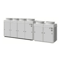
Daikin VRV FXYAP20KV1 Service Manual (193 pages)
Brand:
Daikin
| Category:
Heating System
| Size: 4.03 MB
Table of Contents
Table of Contents
2
Introduction
6
Safety Cautions
6
Preface
10
Part 1 General Information R-407C PLUS Series
12
Product Outline
13
Year 2000 Models Using New Refrigerant
13
Outline of New Series Products
14
Model Configuration and Combination
16
Part 2 Specifications R-407C PLUS Series
18
Specifications
19
Outdoor Unit
19
Indoor Unit
23
Part 3 Function R-407C PLUS Series
42
Outdoor Unit Refrigerant System Diagram
43
Flow of Refrigerant in each Operating Mode
46
List of Safty Device and Function Parts Setting Value
50
Outdoor Unit
50
Indoor Unit
51
Outline of Control (Outdoor Unit)
54
Compressor PI Control
54
Motorized Valve PI Control
55
Defrost Control
56
Low Outside Temperature Cooling Control
58
Compressor Capacity Control
60
Demand Control
62
Restart Standby
63
Startup Control
64
Oil Equalization Operation
65
Oil Return Operation
66
Low Pressure Protection Control
69
High Pressure Protection Control
70
Discharge Pipe Temperature Control
72
Inverter Protection Control
74
Crankcase Heater Control
75
Gas Shortage Warning
76
Heating Pump-Down Residual Operation
77
Backup Operation
78
Fan Location and Fan Tap
79
Outline of Control (Indoor Unit)
80
Drain Pump Control
80
Louver Control for Preventing Ceiling Dirt
82
Thermostat Sensor in Remote Controller
83
Freeze Prevention
85
Part 4 Test Operation R-407C PLUS Series
86
Test Operation
87
Procedure and Outline
87
Operation When Power Is Turned on
89
Outdoor Unit PC Board Ass'y
90
Setting Modes
92
Cool / Heat Mode Selection
99
Low Noise Operation
104
Demand Control
105
Sequential Start
106
Wiring Check Operation
107
Additional Refrigerant Charge Operation
108
Refrigerant Recovery Mode
109
Indoor Field Setting
110
Centralized Control Group No. Setting
116
Contents of Control Modes
118
Part 5 Troubleshooting R-407C PLUS Series
120
Operation Flowcharts
122
Indoor Unit Operation Flowchart
122
Troubleshooting by Remote Controller
127
The INSPECTION / TEST Button
127
Self-Diagnosis by Wired Remote Controller
128
Self-Diagnosis by Wireless Remote Controller
129
Operation of the Remote Controller's Inspection / Test Operation Button
133
Remote Controller Service Mode
134
Remote Controller Self-Diagnosis Function
136
Troubleshooting
139
Indoor Unit: Error of External Protection Device
139
Indoor Unit: PC Board Defect
139
Indoor Unit: Malfunction of Drain Level Control System (33H)
140
Indoor Unit: Fan Motor (M1F) Lock, Overload
141
Indoor Unit: Malfunction of Swing Flap Motor (M1S)
142
Indoor Unit: Malfunction of Moving Part of Electronic Expansion Valve
143
Indoor Unit: Malfunction of Moving Part of Electronic Expansion Valve (Y1E)
143
Indoor Unit: Drain Level above Limit
144
Indoor Unit: Malfunction of Capacity Determination Device
145
Indoor Unit: Malfunction of Thermistor (R2T) for Liquid Pipe
145
Indoor Unit: Malfunction of Thermistor (R3T) for Gas Pipes
146
Indoor Unit: Malfunction of Thermistor (R1T) for Air Inlet
146
Indoor Unit: Malfunction of Thermostat Sensor in Remote Controller
147
Outdoor Unit: Actuation of Safety Device
147
Outdoor Unit: PC Board Defect
148
Outdoor Unit: Actuation of High Pressure Switch
148
Outdoor Unit: Actuation of Low Pressure Sensor
149
Outdoor Unit: Malfunction of Moving Part of Electronic Expansion Valve (Y1E)
150
Outdoor Unit: Abnormal Discharge Pipe Temperature
151
Outdoor Unit: Malfunction of Thermistor for Outdoor Air (R1T)
152
Outdoor Unit: Malfunction of Discharge Pipe Thermistor (R3T)
153
Outdoor Unit: Malfunction of Thermistor (R4T) for Suction Pipe
154
Outdoor Unit: Malfunction of Thermistor (R2T) for Heat Exchanger
155
Outdoor Unit: Malfunction of Discharge Pipe Pressure Sensor
156
Outdoor Unit: Malfunction of Suction Pipe Pressure Sensor
157
Low Pressure Drop Due to Refrigerant Shortage
158
Or Electronic Expansion Valve Failure
158
Reverse Phase, Open Phase
159
Malfunction of Transmission between Indoor Units
160
Malfunction of Transmission between Remote Controller and Indoor Unit
161
Malfunction of Transmission between Outdoor Units
162
Malfunction of Transmission between Master and Slave Remote Controllers
163
Malfunction of Transmission between Indoor and Outdoor Units in the same System
164
Excessive Number of Indoor Units
165
Address Duplication of Central Remote Controller
166
Refrigerant System Not Set, Incompatible Wiring/Piping
166
Malfunction of System, Refrigerant System Address Undefined
167
Failure Diagnosis for Inverter System
168
Points of Diagnosis
168
How to Use the Monitor Switch on the Inverter PC Board
169
Troubleshooting (Inverter)
170
Outdoor Unit: Malfunction of Inverter Radiating Fin Temperature Rise
170
Outdoor Unit: Inverter Instantaneous Over-Current
171
Outdoor Unit: Inverter Thermostat Sensor, Compressor Overload
172
Outdoor Unit: Inverter Stall Prevention, Compressor Lock
173
Outdor Unit: Malfunction of Transmission between Inverter and Control PC Board
174
Power Supply Insufficient or Instantaneous Failure
175
Outdoor Unit: Inverter Over-Ripple Protection
176
Outdoor Unit: Malfunction of Inverter Radiating Fin Temperature Rise Sensor
177
Troubleshooting (OP: Central Remote Controller)
178
Malfunction of Transmission between Central Remote Controller and Indoor Unit
178
PC Board Defect
179
Malfunction of Transmission between Optional Controllers for Centralized Control
179
Improper Combination of Optional Controllers for Centralized Control
180
Address Duplication, Improper Setting
181
Troubleshooting (OP: Schedule Timer)
182
Malfunction of Transmission between Central Remote Controller and Indoor Unit
182
PC Board Defect
183
Malfunction of Transmission between Optional Controllers for Centralized Control
183
Improper Combination of Optional Controllers for Centralized Control
184
Address Duplication, Improper Setting
185
Troubleshooting (OP: Unified ON/OFF Controller)
186
Operation Lamp Blinks
186
Display "Under Host Computer Integrate Control" Blinks (Repeats Single Blink)
187
Display "Under Host Computer Integrate Control" Blinks
189
(Repeats Double Blink)
189
Display "Under Host Computer Integrate Control" Blinks (Repeats Double Blink)
189
Part 6 Special Service Mode R-407C PLUS Series
190
Backup and Emergency Operation
191
Pump down Operation
193
Advertisement
Advertisement
Related Products
Daikin VRV FXYAP32KV1
Daikin VRV FXYAP40KV1
Daikin VRV FXYAP25KV1
Daikin VRV FXYAP63KV1
Daikin VRV FXYAP50KV1
Daikin VRV FXYLP40KJV1
Daikin FXYBP20K7V1
Daikin VRV FXYMP250KV1
Daikin VRV FXYMP80KV1
Daikin VRV FXYSP100KV1
Daikin Categories
Air Conditioner
Heat Pump
Remote Control
Chiller
Fan
More Daikin Manuals
Login
Sign In
OR
Sign in with Facebook
Sign in with Google
Upload manual
Upload from disk
Upload from URL