Sign In
Upload
Manuals
Brands
Parker Manuals
Servo Drives
PSUP10D6
Parker PSUP10D6 Servo Drive System Manuals
Manuals and User Guides for Parker PSUP10D6 Servo Drive System. We have
2
Parker PSUP10D6 Servo Drive System manuals available for free PDF download: Operating Instructions Manual, Installation Manual
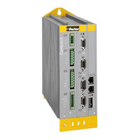
Parker PSUP10D6 Operating Instructions Manual (398 pages)
Positioning via digital I/Os & Com port
Brand:
Parker
| Category:
Servo Drives
| Size: 20 MB
Table of Contents
Inhalt
5
Table of Contents
5
1 Introduction
13
Device Assignment
13
Scope of Delivery
14
Type Specification Plate
15
Packaging, Transport, Storage
16
Safety Instructions
18
General Hazards
18
Safety-Conscious Working
18
Special Safety Instructions
19
Warranty Conditions
20
Conditions of Utilization
21
Conditions of Utilization for CE-Conform Operation
21
Conditions of Utilization Mains Filter
21
Conditions of Utilization for Cables / Motor Filter
22
Additional Conditions of Utilization
23
Conditions of Utilization for UL Certification Compax3S
24
Conditions of Utilization for UL Certification Compax3M
25
Conditions of Utilization for UL Certification Compax3H
26
Current on the Mains PE (Leakage Current)
27
Supply Networks
27
2 C3I12T11 Function Overview
28
3. Compax3 Device Description
30
3 Compax3 Device Description
30
Meaning of the Status Leds - Compax3 Axis Controller
30
In this Chapter You Can Read About: Meaning of the Status Leds - Compax3 Axis Controller
30
Meaning of the Status Leds - PSUP (Mains Module)
31
Connections of Compax3S
32
Compax3S Connectors
32
Connector and Pin Assignment C3S
33
Control Voltage 24VDC / Enable Connector X4 C3S
35
Motor / Motor Brake (C3S Connector X3)
36
Compax3Sxxx V2
37
Main Voltage Supply C3S Connector X1
37
Braking Resistor / High Voltage DC C3S Connector X2
38
Compax3Sxxx V4
40
Power Supply Connector X1 for 3AC 400VAC/480VAC-C3S Devices
40
Braking Resistor / High Voltage Supply Connector X2 for 3AC 400VAC/480VAC_C3S Devices
41
Connection of the Power Voltage of 2 C3S 3AC Devices
41
Installation Instructions Compax3M
42
Psup/Compax3M Connections
44
Front Connector
44
Connections on the Device Bottom
45
Connections of the Axis Combination
46
Control Voltage 24VDC PSUP (Mains Module)
47
Mains Supply PSUP (Mains Module) X41
48
Braking Resistor / Temperature Switch PSUP (Mains Module)
50
Motor / Motor Brake Compax3M (Axis Controller)
52
Temperature Switch PSUP (Mains Module)
52
Measurement of the Motor Temperature of Compax3M (Axis Controller)
53
Safety Technology Option for Compax3M (Axis Controller)
53
3.6 Connections of Compax3H
54
Connections of Compax3H
54
Compax3H Plugs/Connections
54
Connection of the Power Voltage
55
Compax3H Connections Front Plate
57
Plug and Pin Assignment C3H
57
Motor / Motor Brake C3H
59
Control Voltage 24 VDC C3H
60
Mains Connection Compax3H
60
Braking Resistor / Supply Voltage C3H
61
Connect Braking Resistor C3H
61
Power Supply Voltage DC C3H
61
Connection of the Power Voltage of 2 C3H 3AC Devices
62
Communication Interfaces
63
RS232/RS485 Interface (Plug X10)
63
Communication Compax3M
64
Communication in the Axis Combination (Connector X30, X31)
64
PC - PSUP (Mains Module)
64
Adjusting the Basic Address
65
Setting the Axis Function
65
Signal Interfaces
66
Resolver / Feedback (Plug X13)
66
Analogue / Encoder (Plug X11)
67
Connections of the Encoder Interface
67
Wiring of Analog Interfaces
67
Digital Inputs/Outputs (Plug X12)
68
Connection of the Digital Outputs/Inputs
69
Logic Proximity Switch Types
69
Installation and Dimensions Compax3
70
Mounting and Dimensions Compax3S
70
Mounting and Dimensions Compax3S0Xxv2
70
Mounting and Dimensions Compax3S100V2 and S0Xxv4
71
Mounting and Dimensions Compax3S150V2 and S150V4
72
Mounting and Dimensions Compax3S300V4
73
Mounting and Dimensions PSUP/C3M
74
Mounting and Dimensions PSUP10/C3M050D6, C3M100D6, C3M150D6
74
Mounting and Dimensions PSUP20/PSUP30/C3M300D6
75
With Upper Mounting, the Housing Design May be Different
75
Mounting and Dimensions C3H
76
Mounting Distances, Air Currents Compax3H050V4
77
Mounting Distances, Air Currents Compax3H090V4
77
Mounting Distances, Air Currents Compax3H1Xxv4
78
Safety Function - STO (=Safe Torque Off)
79
General Description
79
Important Terms and Explanations
79
Advantages of Using the "Safe Torque Off" Safety Function
80
Intended Use
80
Devices with the STO (=Safe Torque Off) Safety Function
81
STO (= Safe Torque Off) with Compax3S
82
STO Principle (= Safe Torque Off) with Compax3S
82
Conditions of Utilization STO (=Safe Torque Off) Safety Function
84
Notes on the STO Function
84
STO Application Example (= Safe Torque Off)
86
Technical Characteristics STO Compax3S
89
3.10.3. Sto (= Safe Torque Off) with Compax3M (Option S1)
90
In this Chapter You Can Read About: Safety Switching Circuits
90
STO (= Safe Torque Off) with Compax3M (Option S1)
90
Safety Switching Circuits
90
Conditions of Utilization for the STO Function with Compax3M
91
Safety Notes for the STO Function in the Compax3M
91
STO Delay Times
92
Compax3M STO Application Description
93
STO Function Test
96
Technical Details of the Compax3M S1 Option
98
Parker Eme 4. Setting up Compax3
99
4 Setting up Compax3
99
Configuration
99
Compax3M
100
Test Commissioning of a Compax3 Axis
101
Selection of the Supply Voltage Used
101
Motor Selection
101
In this Chapter You Can Read About: Test Commissioning of a Compax3 Axis
101
Optimize Motor Reference Point and Switching Frequency of the Motor Current
102
Ballast Resistor
105
General Drive
105
Defining the Reference System
106
Measure Reference
106
Parker Eme 4.1.7.2 Machine Zero
109
Machine Zero
109
Positioning after Homing Run
110
Absolute Encoder
111
Operation with Multiturn Emulation
111
Machine Zero Modes Overview
112
Homing Modes with Home Switch (on X12/14)
114
Machine Zero Modes Without Home Switch
120
Adjusting the Machine Zero Proximity Switch
125
Machine Zero Speed and Acceleration
125
Travel Limit Settings
126
Change Assignment Direction Reversal / Limit Switches
129
Change Initiator Logic
129
Defining Jerk / Ramps
130
Jerk Limitation
130
Ramp Upon Error / Deenergize
131
Limit and Monitoring Settings
133
Current (Torque) Limit
133
Positioning Window - Position Reached
133
Following Error Limit
135
Maximum Operating Speed
135
Operating Mode / I/O Assignment
136
I/O Assignment for Control Via the Compax3 Inputs/Outputs
136
I/O Assignment, Control Word and Status Word with Control Via COM Port
137
Encoder Simulation
141
Encoder Bypass with Feedback Module F12 (for Direct Drives)
141
Absolute- /Continuous Mode
141
Position Mode in Reset Operation
142
Examples in the Help File
142
Defining the STOP Function
142
Reg-Related Positioning / Defining Ignore Zone
144
Write into Set Table
145
Dynamic Positioning
145
Programmable Status Bits (Psbs)
146
Moveabs and Moverel
147
Set Selection
147
Reg-Related Positioning (Regsearch, Regmove)
148
Electronic Gearbox (Gearing)
152
Speed Specification (Velocity)
153
Stop Command (Stop)
153
Error Response
153
Configuration Name / Comments
154
Configuring the Signal Source
155
Signal Source of the Load Feedback System
155
Select Signal Source for Gearing
155
Encoder A/B 5V, Step/Direction or SSI Feedback as Signal Source
156
Signal Source HEDA
156
+/-10V Analog Speed Setpoint Value as Signal Source
158
Load Control
160
Configuration of Load Control
162
Error: Position Difference between Load Mounted and Motor Feedback too High
163
Load Control Signal Image
163
Object for the Load Control (Overview)
164
Objects for Load Control
164
Optimization
165
Optimization Window
166
Scope
167
Monitor Information
167
User Interface
168
Example: Setting the Oscilloscope
173
Controller Optimization
175
Introduction
175
4.4.3.2 Configuration
178
Configuration
178
In this Chapter You Can Read About: Control Path
178
Mass Inertia
179
Motor Parameters Relevant for the Control
179
Nominal Point Data
179
Quality of Different Feedback Systems
181
Saturation Values
181
Typical Problems of a Non Optimized Control
182
Feedback Error Compensation
183
Commutation Settings
184
I²T - Monitoring of the Motor
184
Relevant Application Parameters
187
Parker Eme
191
Asynchronous Motors
191
In this Chapter You Can Read About: Type Specification Plate Data
191
Replacement Switching Diagram - Data for a Phase
192
Slip Frequency
192
Cut-Off Frequency for the Field Weakening Range
193
Saturation Behavior
193
Asynchronous Motors: Extension of the Controller Structure
194
Automatic Controller Design
195
Determination of the Commutation Settings
194
Rotor Time Constant
194
Parker Eme 4.4.3.4 Setup and Optimization of the Control
207
Setup and Optimization of the Control
207
Standard
208
Advanced
214
Commissioning Window
229
Proceeding During Controller Optimization
231
Signal Filtering with External Command Value
240
Signal Filtering for External Setpoint Specification and Electronic Gearbox
240
Signal Filtering for External Setpoint Specification and Electronic Cam
241
Input Simulation
242
Calling up the Input Simulation
242
Operating Principle
243
Setup Mode
244
Motion Objects in Compax3
245
Load Identification
246
Boundary Conditions
246
Principle
246
Process of the Automatic Determination of the Load Characteristic Value (Load Identification)
247
Tips
248
Alignment of the Analog Inputs
249
Gain Alignment
249
Offset Alignment
249
Signal Processing of the Analog Inputs
250
Parker Eme 4.4.9. C3 Servosignalanalyzer
251
C3 Servosignalanalyzer
251
Servosignalanalyzer - Function Range
251
Signal Analysis Overview
252
Installation Enable of the Servosignalanalyzer
253
Analyses in the Time Range
255
Measurement of Frequency Spectra
258
Measurement of Frequency Responses
261
4.4.9.7 Overview of the User Interface
268
In this Chapter You Can Read About: Selection of the Signal or System to be Measured
268
Overview of the User Interface
268
Mechanical System
270
Position Control
271
Frequency Settings
273
Speed Control
273
Other Settings
275
Operating and Status Field
277
Display of the Measurement Result
279
Display of the Measurement Point at the Cursor Position
280
Basics of Frequency Response Measurement
281
In this Chapter You Can Read about
281
Examples Are Available as a Movie in the Help File
286
Profileviewer for the Optimization of the Motion Profile
287
Input Values
287
Mode 1: Time and Maximum Values Are Deduced from Compax3
287
Mode 2: Compax3 Input Values Are Deduced from Times and Maximum Values
288
Turning the Motor Holding Brake on and off
289
5. Control Via Rs232 / Rs485 / Usb
290
5 Control Via RS232 / RS485 / USB
290
Status Diagram
291
I/O Assignment, Control Word and Status Word with Control Via COM Port
292
I/O Assignment
292
Control Word
294
Status Word 1 & 2
295
Examples Include: Control Via COM Port
296
Layout of the Set Table
299
Assignment of the Different Motion Functions
299
General Layout of the Table
299
Definition of the States of the Programmable Status Bits (Psbs)
300
Compax3 Communication Variants
300
Compa3 Communication Variants
300
PC <-> Compax3 (RS232)
301
PC <-> Compax3 (RS485)
303
PC <-> C3M Device Combination (USB)
304
USB-RS485 Moxa Uport 1130 Adapter
305
ETHERNET-RS485 Netcom 113 Adapter
306
Modem MB-Connectline MDH 500 / MDH 504
307
C3 Settings for RS485 Two Wire Operation
308
C3 Settings for RS485 Four Wire Operation
309
COM Port Protocol
310
RS485 Settings Values
310
ASCII - Record
311
Binary Record
312
Remote Diagnosis Via Modem
315
Structure
316
Configuration of Local Modem 1
317
Configuration of Remote Modem 2
317
Recommendations for Preparing the Modem Operation
318
6 Compax3 - Objects
319
Object Overview I12 T11
319
Detailed Object List
322
7 Status Values
323
D/A-Monitor
323
8 Error
324
Error List
324
9 Order Code
325
Order Code Device: Compax3
325
Order Code for Mains Module: PSUP
326
Order Code for Accessories
326
10 Compax3 Accessories
330
Parker Servo Motors
330
Direct Drives
330
Transmitter Systems for Direct Drives
331
Linear Motors
332
Rotary Servo Motors
332
Torque Motors
332
EMC Measures
333
Mains Filter
333
Mains Filter NFI01/01
334
Mains Filter NFI01/02
334
Mains Filter for NFI01/03
335
Mains Filter Nfi02/0X
335
Mains Filter NFI03/01& NFI03/03
336
Mains Filter NFI03/02
337
Motor Output Filter
338
Motor Output Filter MDR01/01
338
Motor Output Filter MDR01/04
338
Motor Output Filter MDR01/02
339
Wiring of the Motor Output Filter
339
Mains Filter for PSUP30
340
Mains Filters
340
Connections to the Motor
341
Resolver Cable
342
Sincos© Cable
343
Endat Cable
344
Motor Cable
344
Connection of Terminal Box MH145 & MH205
345
Encoder Cable
346
External Braking Resistors
347
10.4.1. Permissible Braking Pulse Powers of the Braking Resistors
348
Permissible Braking Pulse Powers of the Braking Resistors
348
Calculation of the BRM Cooling Time
349
In this Chapter You Can Read About: Calculation of the BRM Cooling Time
349
Permissible Braking Pulse Power: BRM08/01 with C3S015V4 / C3S038V4
350
Permissible Braking Pulse Power: BRM08/01 with C3S025V2
350
Permissible Braking Pulse Power: BRM09/01 with C3S100V2
351
Permissible Braking Pulse Power: BRM10/01 with C3S150V4
351
Permissible Braking Pulse Power: BRM05/01 with C3S063V2
352
Permissible Braking Pulse Power: BRM10/02 with C3S150V4
352
Permissible Braking Pulse Power: BRM05/01 with C3S075V4
353
Permissible Braking Pulse Power: BRM05/02 with C3S075V4
353
Permissible Braking Pulse Power: BRM04/01 with C3S150V2
354
Permissible Braking Pulse Power: BRM04/01 with C3S300V4
354
Permissible Braking Pulse Power: BRM04/02 with C3S150V2
355
Permissible Braking Pulse Power: BRM04/02 with C3S300V4
355
Permissible Braking Pulse Power: BRM04/03 with C3S300V4
356
Permissible Braking Pulse Power: BRM11/01 with C3H0Xxv4
356
Permissible Braking Pulse Power: BRM12/01 with C3H1Xxv4
357
Permissible Braking Pulse Power: BRM13/01 with PSUP10D6
357
Permissible Braking Pulse Power: BRM14/01 with PSUP10D6
357
BRM5/01 Braking Resistor
358
Brm8/01Braking Resistors
358
Dimensions of the Braking Resistors
358
Ballast Resistor Brm4/0X and BRM10/02
359
Braking Resistor BRM5/02, BRM9/01 & BRM10/01
359
Ballast Resistor BRM13/01 & BRM14/01
360
Braking Resistor BRM11/01 & BRM12/01
360
Condenser Module C4
361
Operator Control Module BDM
362
EAM06: Terminal Block for Inputs and Outputs
363
Interface Cable
365
RS232 Cable
365
RS485 Cable to Pop
366
I/O Interface X12 / X22
367
Ref X11
367
Encoder Coupling of 2 Compax3 Axes
368
Modem Cable SSK31
369
Options M1X
370
Assignment of the X22 Connector
370
Input/Output Option M12
370
HEDA (Motion Bus) - Option M11
371
Option M10 = HEDA (M11) & I/Os (M12)
373
11 Technical Characteristics
374
12 Index
392
Advertisement
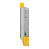
Parker PSUP10D6 Installation Manual (28 pages)
Mains modules
Brand:
Parker
| Category:
Control Unit
| Size: 1 MB
Table of Contents
Table of Contents
3
In this Chapter You Can Read About: Device Assignment
4
Scope of Delivery
5
Packaging, Transport, Storage
6
Safety Instructions
7
General Hazards
7
1 Introduction
4
Device Assignment
4
Safety-Conscious Working
7
Special Safety Instructions
8
Warranty Conditions
9
Conditions of Utilization for CE-Conform Operation
10
Conditions of Utilization for UL Approval PSUP
11
Current on the Mains PE (Leakage Current)
12
Supply Networks
12
EC Declaration of Conformity PSUP
13
2 Device Description
14
Meaning of the Status Leds - PSUP (Mains Module)
14
Mounting and Dimensions
15
Mounting and Dimensions PSUP10
15
Mounting and Dimensions PSUP20/PSUP30
16
PSUP Connections
17
Front Connector
17
In this Chapter You Can Read About: Front Connector
17
Connections on the Device Bottom
18
Connections of the Axis Combination
19
Control Voltage 24VDC PSUP (Mains Module)
20
Mains Supply PSUP (Mains Module) X41
20
Braking Resistor / Temperature Switch PSUP (Mains Module)
23
Communication Interfaces
24
Adjusting the Basic Address
24
3 Technical Characteristics
25
4 Index
28
Advertisement
Related Products
Parker PSUP20D6
Parker P Series
Parker PSD1
Parker PSD1-SW1300
Parker PSD1-M_1300
Parker PSD1-M_1400
Parker PSD1-M_1600
Parker PSD1-M_2630
Parker PSD1-MWP010
Parker PSD1-MWP020
Parker Categories
Controller
Control Unit
Industrial Equipment
Water Filtration Systems
DC Drives
More Parker Manuals
Login
Sign In
OR
Sign in with Facebook
Sign in with Google
Upload manual
Upload from disk
Upload from URL