Table of Contents
Advertisement
Quick Links
Advertisement
Table of Contents

Related Manuals for Touch Dynamic Saturn All-in-one


Summary of Contents for Touch Dynamic Saturn All-in-one
- Page 1 USER MANUAL VERSION V1.0 DECEMBER 2009 Saturn All-in-one Hardware system...
- Page 2 Copyright 2009 All Rights Reserved Manual Version 1.0 Part Number: The information contained in this document is subject to change without notice. We make no warranty of any kind with regard to this material, including, but not limited to, the implied warranties of merchantability and fitness for a particular purpose.
-
Page 3: Important Safety Instructions
Safety IMPORTANT SAFETY INSTRUCTIONS To disconnect the machine from the electrical power supply, turn off the power switch and remove the power cord plug from the wall socket. The wall socket must be easily accessible and in close proximity to the machine. Read these instructions carefully. -
Page 4: Legislation And Weee Symbol
CAUTION ON LITHIUM BATTERIES There is a danger of explosion if the battery is replaced incorrectly. Replace only with the same or equivalent type recommended by the manufacturer. Discard used batteries according to the manufacturer’s instructions. LEGISLATION AND WEEE SYMBOL 2002/96/EC Waste Electrical and Electronic Equipment Directive on the treatment, collection, recycling and disposal of electric and electronic devices and their components. -
Page 5: Revision History
Revision History Changes to the original user manual are listed below: Revision Description Date • Initial release 2009 December... -
Page 6: Table Of Contents
Table of Contents 1. Packing List ......1 1-1. Standard Accessories ..........1 1-2. Optional Accessories ..........1 2. System View ......2 2-1. Front View ...............2 2-2. Side View ..............2 2-3. Rear View ..............3 2-4. I/O view ..............4 2-5. Dimensions ..............5 2-5-1. - Page 7 6. Jumper Setting ......13 6-1. Motherboard Layout ..........13 6-2. Connectors & Functions .........14 6-3. Jumper Setting ............15 6-3-1. System Reset Settings ..........15 6-3-2. COM3 & COM4 Power Setting ........ 15 6-3-3. Cash Drawer Power Setting ........16 6-3-4. Power Mode Setting ..........16 6-3-5.
-
Page 8: Packing List
Packing List 111. Standard Accessories System Driver bank User guide Power adapter Power cord RJ45-DB9 cable (x2) 112. Optional Accessories Stand WLAN Card + internal antenna pSSD module + bracket... -
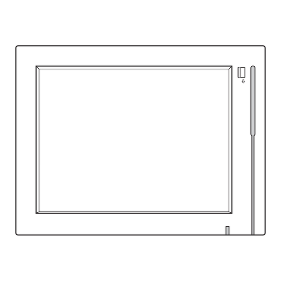
Page 9: System View
System View 211. Front View Without Stand With Stand Metal Stand Touch Screen Built-in MSR 212. Side View Ventilation holes... -
Page 10: Rear View
213. Rear View 8.4" System 10.4" System 12.1" System 12.1" Fanless System PS/2 19V IN COM4 COM3 COM2 COM1 PS/2 19V IN COM4 COM3 COM2 COM1 VESA Mounting Holes Ventilation HDD Door (12.1") -
Page 11: I/O View
214. I/O view a b c d e Item No. Description Line-Out Power LED indicator PS/2 Power Button DC Jack 2nd VGA COM Port 1, 2, 3, 4 (from right to left) LAN (10/100/1000) USB x 4 Cash Drawer Port Note: The location of the I/O ports may vary slightly, depending on whether you have a system with or without fan. -
Page 12: Dimensions
212. Dimensions 21211. 8.4" System 251.6 50 ° 183.5 21212. 10.4" System 283.8 50 ° 180.5 21213. 12.1 System 50 ° 193.2... -
Page 13: System Assembly
System Assembly 311. RAM Module Replacement Removing a RAM module Please Open the rear cover by unfastening the screws (x8) to access the motherboard. (See Chapter 3-2) Use both fingers to pull the ejector clips out of the sides of the module. Slide out to remove the memory module from the memory slot. -
Page 14: Hdd Replacement
312. HDD Replacement To remove and replace the HDD, please follow the steps below. The procedure is different depending on the 8.4”, 10.4” or 12.1” system being installed. 31211. HDD replacement for 8.4” and 10.4” system The HDD is installed on the motherboard, you need to uncover the rear cover first to access it. -
Page 15: Hdd Replacement For 12.1" System
31212. HDD replacement for 12.1” system You can access the HDD easily by turning the system to the rear side on a 12” system. Please see detailed procedure below. Turn to the rear side of the system to access the HDD door. Unscrew the screw (x1) securing the HDD door to the rear cover of the system. -
Page 16: Peripheral Installation
Peripheral Installation 411. Stand Installation Fasten the screws (x4). The screw location may slightly differ according to the system size (8.4”, 10.4” or 12.1”) being installed. 412. pSSD Card Module Installation Accessories of pSSD card module: a. pSSD Card b. Metal bracket c. -
Page 17: Cash Drawer Installation
413. Cash Drawer Installation You can install a cash drawer through the cash drawer port. Please verify the pin assignment of your cable before installation. Cash Drawer Pin Assignment Signal DOUT bit0 DIN bit0 12V / 19V DOUT bit1 Cash Drawer Controller Register The Cash Drawer Controller use one I/O address to control the Cash Drawer. - Page 18 Bit 7: Reserved Bit 6: Cash Drawer “DIN bit0” pin input status. = 1: the Cash Drawer closed or no Cash Drawer = 0: the Cash Drawer opened Bit 5: Reserved Bit 4: Reserved Bit 3: Cash Drawer “DOUT bit1” pin output control. = 1: Opening the Cash Drawer = 0: Allow close the Cash Drawer Bit 2: Cash Drawer “DOUT bit0”...
-
Page 19: Specification
Specification Motherboard Processor Intel® AtomTM processors N270 1.6G L2 512K FSB 533MHz Chipset Intel® 945GSE Express chipset + ICH7M System Memory 1 X DDR2 DIMM up to 2GB FSB 533MHz Graphic Memory Intel® GMA 950 share system memory up to 224MB LCD / Touch Panel LCD Size 8.4"... -
Page 20: Jumper Setting
Jumper Setting 611. Motherboard Layout SATA3 DDR2-A1 CN23 CN22 Version: C36A v1.1... -
Page 21: Connectors & Functions
612. Connectors & Functions Connector Purpose BAT3 CMOS Battery Base ( Use CR2023) Speaker & MIC Connector Power Connector For HDD USB5 USB7 LAN LED Card Reader Connector CN12 IrDA Connector CN13 Inverter Connector CN15 Power LED CN16 LCD Interface Connector CN17 Internal DC-JACK connector CN21... -
Page 22: Jumper Setting
613. Jumper Setting 61311. System Reset Settings Function JP7 (1-2) ▲Normal Reset 61312. COM3 & COM4 Power Setting Function 5 7 9 11 ▲RI 6 8 10 12 5 7 9 COM3 Pin10 8 10 5 7 9 +12V 8 10 5 7 9 ▲RI 8 10... -
Page 23: Cash Drawer Power Setting
61313. Cash Drawer Power Setting Function ▲+12V +19V 61314. Power Mode Setting Function ▲ATX Power AT Power 61312. CMOS Operation Mode Function ▲CMOS Normal CMOS Reset 61316. VGA Power Setting Function ▲No Power +12V ▲ = Manufacturer Default Setting... -
Page 24: Lcd Id Setting
61317. LCD ID Setting LVDS Output Panel# Resolution Bits Channel Interface 1366 x 768 Single LVDS 1440 x 990 Dual LVDS 1920 x 1080 Dual LVDS 1024 x 768 Single LVDS 1280 x 1024 Dual LVDS 800 x 600 Single LVDS 1024 x 768 Single... -
Page 25: Appendix: Drivers Installation
Appendix: Drivers Installation The shipping package includes a Driver CD in which you can find every individual driver and utility that enables you to install the drivers on the system. Please insert the Driver CD into the drive and double click on the “index.htm” to select the models.
Need help?
Do you have a question about the Saturn All-in-one and is the answer not in the manual?
Questions and answers