Table of Contents
Advertisement
Advertisement
Table of Contents

Subscribe to Our Youtube Channel
Related Manuals for Touch Dynamic Atlas All-in-one


Summary of Contents for Touch Dynamic Atlas All-in-one
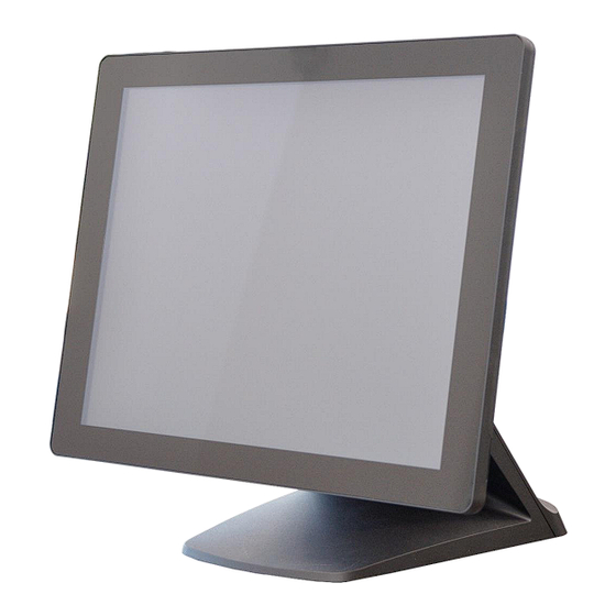
- Page 1 Atlas All-in-one User Manual Version:0.2 Version:1.0 Version: 1.0...
- Page 2 Copyright Copyright 2018 Touch Dynamic. All Rights Reserved. This manual, software and firmware described in it are copyrighted by their respective owners and protected under the laws of the Universal Copyright Convention. You may not reproduce, transmit, transcribe, store in a retrieval system, or translate into any language, in any form or by any means, electronic, mechanical, magnetic, optical, chemical, biological, molecular, manual, or otherwise, any part of this publication without the express written permission of the publisher.
-
Page 3: Safety Instructions
Safety Instructions Read these instructions carefully. Keep these instructions for future reference. Please disconnect this equipment from AC outlet before cleaning. Don’t use liquid or sprayed detergent for cleaning. Use moisture sheet or cloth for cleaning. Please keep this equipment from humidity. Lay this equipment on a reliable surface when install. -
Page 4: Fcc Notice
CE Notice This device complies with the requirements of the CE directive. FCC Notice This equipment has been tested and found to comply with the limits for a Class A digital device, pursuant to Part 15 of the FCC rules. These limits are designed to provide reasonable protection against harmful interference in a residential installation. -
Page 5: Packing List
Packing List Standard Accessories System (with Stand) Power Cord and power supply (3-pin) -
Page 6: System View
System View 2-1 I/O View ☆ Please make sure 19V DC plug in the right direction before plugging in DC jack. 2-2 Back View... - Page 7 2-4 Specification Display Size 15" TFT LCD Resolution 1024 X 768 Display 300 cd/㎡ , 16.7M colors Brightness / Color Backlight Touch Panel Type Projected Capacitive Touch Intel® Celeron J1900 Quad-Core 2.0Ghz up to 2.42Ghz Processor CPU/ Chipset Memory X 1 DDR3L SO-DIMM, up to 8GB X 1 (2.5”...
- Page 8 2-4 Internal Layout M/B PCBA Panel Back light LVDS SATA II 19V DC OUT Touch DDR3L Slot POWER BUTTON POWER LED DC IN 19V RJ45 RJ11 USB2.0 USB2.0&3.0 LINE OUT...
-
Page 9: Pin Definition
Pin Definition 1. LVDS connector Definition Definition 6-bit/8-bit selection DATA3+ DATA3- CLK+ CLK- DATA2+ DATA2- DATA1+ DATA1- DATA0+ DATA0- +3.3V +3.3V 2. SATA Definition Definition SATA_TX0_P SATA_TX0_N SATA_RX0_N SATA_RX0_P... - Page 10 3. Power On/Off connector Definition +5V Standby +5V Status Power On# 4. Projected capacitive touch connector Definition USB D- USB D+ 5. Resistive touch connector Definition 6. Sideward MSR connector Pin Definition Definition USB D- USB D+...
- Page 11 7. VFD connector Definition RTS# DSR# CTS# DTR# USB D- USB D+ 8. CN1: MB to small card connector Definition +19V +19V...
-
Page 12: Rear I/O Interface
Rear I/O Interface System 1. DC Jack Pin Definition Definition +19V Ground +19V 2. 2-Layer USB2.0 connector Pin Definition Definition Definition 3. 2-Layer USB3.0+2.0 connector Pin Definition Definition Definition... - Page 13 4. LAN: RJ45 Pin Definition Wire color(T568B) Definition White / Orange Transmit Orange Transmit White / Green Receive Blue 1000Base-T White / Blue 1000Base-T Green Receive White / Brown 1000Base-T Brown 1000Base-T 5. COM connector Pin Definition Definition DCD# DTR# DSR# RTS# CTS#...
- Page 14 6. RJ11 (Cash Drawer) connector Pin Definition Definition C/D_OPEN# C/D Status +24V 7. Line-out Jack Pin Definition Definition LINE_OUT LINE_OUT Detect 8. JS1: Small card to printer connector Pin Definition Definition +24V +24V 4. Cash Drawer Definition Drawer 1 DRSW Drawer 2 Electrical characteristics .Driving voltage : DC 24V;...
-
Page 15: System Assembly & Disassembly
System Assembly & Disassembly 5-1. HDD 1. Loosen the 2 screws. 2. Pull out the hard tray case in an outward direction to remove it from the system. 3. Install the hard drive in the hard drive case and fasten 4 hard drive case screws. - Page 16 5-2. Memory Loosen 11 screws and remove the back cover. Insert the RAM into the RAM slot. 5-4. VFD / 8”/ 9.7” or 10” 2 Display 1. Remove top cover. 2. Either plug the VFD cable into the VFD connector or plug the 8” or 10” 2 display cable into the...
-
Page 17: 2D Barcode Scanner
display’s connector (note: display connector can only be connected to one device at a time). 3. Install VFD with 2 screws / Install 8”or 10”2nd display with 2 screws. 5-5. 1D/2D Barcode Scanner 1. Install the barcode scanner with bracket attached by tightening the 2 screws 2. -
Page 18: Device Driver Installation
Device Driver Installation 6-1. VFD 1. Power on VFD and waiting test page of EEPROM test, Baud rate and Command page. Set up the customer display by " VFDset.exe” 2. Setup VFDset.exe software. - Page 19 3. To execute “VFDset.exe” for setting up communication between software and VFD module. Please then follow the steps as shown in the above figure, the baud rate will show on states page of VFD module (Note: You may check it when power on VFD module), then click “Open COM” button.
- Page 20 6. Click “Set All Default” button to show default setting, the Default table is Character Type :USA Command Type :EPSON/EURPOPE Baud Rate Setting :9600/n/8/1 Pass-through Mode :None Welcome msg line1 :*** VFD DISPLAY *** Welcome msg line2 :**HAVE A NICE DAY AND THANK YOU 7.
- Page 21 Like the first character (0x80),in default code page will show on VFD module. 8. Click “Download setting to VFD” button This button is to download the setting from VFDset.exe to VFD module. After success dialog “Download O.K! Please restart!” message popped up. Please restart display for enable new setting 9.
- Page 23 10. Click “Load” button After saving, you must restart the utility here. Then load your setting rename-GOODLUCK.vfd.
-
Page 24: Bios/Utility Setup
BIOS/Utility setup BIOS/Utility setup 1. Press <DEL > key to enter SETUP CMOS UTILITY when system boot up. 2. Press <ENTER >over SCU button to enter the utility. - Page 25 7-1. Advanced Use the Advanced menu to configure the system for basic operation through the following sub- menus:...
-
Page 26: Boot Configuration
7-1-1. Boot Configuration Use the Boot Configuration menu to select power-on state for Numlock. -
Page 27: Audio Configuration
7-1-2. Audio Configuration Use the Audio Configuration menu to read Audio configuration information and configure the Audio settings... -
Page 28: Video Configuration
7-1-3. Video Configuration Use the Video Configuration menu to read Video configuration information and configure the Video settings... -
Page 29: Sata Configuration
7-1-4. SATA Configuration Use the SATA Configuration menu to read SATA configuration information and configure the SATA settings... - Page 30 7-2. Security Use the Security menu to install or change the password...
- Page 31 7-3. Power Use the power menu to install or change the power settings. AC Loss Auto Restart Enable or disable system power on automatically after AC power restored Wake on LAN Enable or disable system wake by onboard LAN chip LVDS Firmware update This item allows you to enable or disable LVDS Firmware update...
- Page 32 7-4. Boot Use the Boot menu to select type to Dual type, Legacy type or UEFI type.
- Page 33 7-5. Exit Use the Save & Exit menu to load default BIOS values, optimal failsafe values or to save configuration changes.
-
Page 34: Lcd Surface Cleaning
LCD surface cleaning 1. How to clean the LCD surface properly? ☆ Do not spray any liquids on the LCD screen directly, and do not use paper towels, this can cause the LCD screen to become scratched. ☆ Always apply the solution to your cloth first, not directly to the parts you are cleaning. You want to avoid dripping the solution directly into your computer or laptop.
Need help?
Do you have a question about the Atlas All-in-one and is the answer not in the manual?
Questions and answers