Table of Contents
Advertisement
Quick Links
Advertisement
Table of Contents

Subscribe to Our Youtube Channel
Related Manuals for Magma ExpressBox EB3600-P


Summary of Contents for Magma ExpressBox EB3600-P
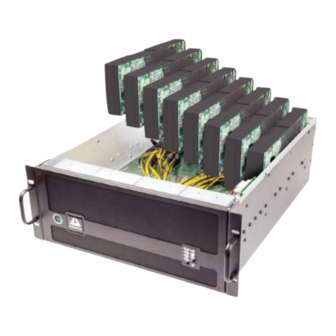
- Page 1 EB3600-P User Manual PCIe to PCIe Expansion MODEL EB3600-P...
-
Page 2: Table Of Contents
Magma Table of Contents Preface ........................... 6 Advisories ..................................6 Safety Instructions ................................7 Chapter 1 Introduction ..................... 9 EB3600-P ................................... 9 OVERVIEW ..................................9 FEATURES ..................................9 BENEFITS .................................... 9 EB3600-P Technical Specification ..........................10 Pre-Installation Information ............................11 Parts List .................................. - Page 3 Magma Is it ok to connect four 1200W Power Supply modules to 120V? ..............35 Use two separate circuit lines..........................36 Do not use multiple electrical outlets on one circuit line................. 36 Power on EB3600-P ............................... 38 Power on Computer ..............................39 Hardware Check ................................
- Page 4 Magma NetBurner Interface Board Installation ......................... 63 Power Supply unit ................................. 64 How to replace the power supply module ......................64 How to Add Power Module to EB3600 ......................... 66 Power Supply Specifications ..........................67 Chapter 4 Express I/O Manager ..................71 Web Server and SNMP Features ..........................
- Page 5 Cleaning the Air Filter ..............................101 Chapter 9 Frequently Asked Questions (FAQ) ............... 102 Chapter 10 How to Get More Help ................. 104 Contacting Technical Support ..........................104 Returning Merchandise to MAGMA ........................104 Appendix A Compliance ............................ 105 EB3600-P |...
-
Page 6: Preface
Disclaimer: We have attempted to identify most situations that may pose a danger, warning, or caution condition in this manual. However, Magma does not claim to have covered all situations that might require the use of a Caution, Warning, or Danger indicator. -
Page 7: Safety Instructions
Magma Safety Instructions Always use caution when servicing any electrical component. Before handling the Magma Expansion chassis, read the following instructions and safety guidelines to prevent damage to the product and to ensure your own personal safety. Refer to the “Advisories” section for advisory conventions used in this manual, including the distinction between Danger, Warning, Caution, Important, and Note. - Page 8 Static electricity can harm system boards. Perform service at an ESD workstation and follow proper ESD procedures to reduce the risk of damage to components. Magma strongly encourages you to follow proper ESD procedures, which can include wrist straps and smocks, when servicing equipment.
-
Page 9: Chapter 1 Introduction
Introduction EB3600-P Magma’s ExpressBox 3600-P provides partitioned support for server grade GPUs and other HPC peripherals to existing host computer systems. Designed to support full Gen 3 x16 PCIe connectivity to all devices, the EB3600-P supports 128 Gbps communication between the host and all peripherals. The EB3600-Psupports eight total peripherals with four host links for support of one to four independent hosts. -
Page 10: Eb3600-P Technical Specification
Magma EB3600-P Technical Specification BASE MODEL EB3600-P -Two partitioned backplanes composed of two segments per backplane with two peripheral slots per segment. Four total segments, eight total peripherals; Supports up to 8 GPUs. - Two 1200W (2400W total) PSUs TECHNOLOGY PCI Express Bus Specification PCI Express Bus Specification 3.0, 2.3;... -
Page 11: Pre-Installation Information
Magma Pre-Installation Information Before using the Magma Expansion chassis, you should perform the following steps: Inventory the shipping carton contents for all of the required parts Gather all of the necessary tools required for installation Read this manual... -
Page 12: Components Of Eb3600-P Unit
Magma Components of EB3600-P unit Once you have completed your inventory, your next step is to be familiarized with components of the Magma EB3600-P expansion unit. The expansion unit is composed of the following integral components Expansion Backplane a. 10 PCIe x16 slot (electronic and mechanical) b. - Page 13 Magma EB3600-P | Chapter 1 Introduction...
-
Page 14: Pre-Installation Information
Gather all of the necessary tools required for installation Read this manual Tools Required for Installation To complete the installation of the Magma product you will need a Phillips-head screwdriver and ESD wrist strap to prevent electrostatic discharge. EB3600-P |... -
Page 15: Chapter 2 Hardware Installation
Magma Chapter 2 Hardware Installation The following steps will guide you through the installation of your Magma Expansion System. CAUTION Hardware installation shall be performed only by qualified service personnel. Electrostatic Discharge (ESD) Warning All add-in cards are susceptible to electrostatic discharge. When moving cards, it is best to carry the cards in anti-static packaging. -
Page 16: Open Enclosure
Expansion Interface card Installation The Magma “Expansion” interface is the same card as the “Host” interface card only that its SW4 switch is set to “ON=EXP.” By default, the expansion interface card should already be installed in the Magma Expansion chassis. - Page 17 Magma EB3600-Pcomes with 2 Expansion Interface cards. There are two separate PCB backplanes side-by-side in the chassis. Each PCB backplane requires one Expansion Interface card linked to the host computer / server. It is Gen3 x16; it has two available cable ports for linking either by x8 or x16 connection.
- Page 18 Magma Backplane with Expansion Interface cards installed, see picture below EB3600-P | Chapter 2 Hardware Installation...
-
Page 19: Host Interface Card Installation
PCIe slot. When the Magma interface card is used as “Host” interface i.e. installed in the host computer, the RED switch should remain OFF. Check the DIP switch and make sure it is set to OFF=HOST. - Page 20 Magma Install the two Magma PCIe host interface cards into the host computer. Use available x16 PCIe slot for both Host Interface cards. Plug in the host card to the PCIe slot closest to the PCIe CPU, this allows the BIOS to enumerate the host card first.
-
Page 21: Host Card Installation In A Slot-Carrier Housing
Magma Host Card installation in a Slot-Carrier housing You have to remove the slot-carrier housing from the host server in order to install the interface card. Remove slot-carrier housing Install Interface card Secure Interface card EB3600-P | Chapter 2 Hardware Installation... -
Page 22: Cable Installation
Magma Put the slot-carrier housing back into the host server Cable Installation The EB3600-P expansion unit uses High Speed / High Density IO cables (HDLSP- High Density Low Skew Pair cable) that deliver superior performance. It is an ideal solution for super-computing and data storage applications including servers, blade servers, and server clusters, providing vast modularity between systems and subsystem. -
Page 23: Connect Cables To Expansion Unit
Magma Connect cables to expansion unit FOR EB3600-P, you need four cables. Plug in cables to Magma EB3600-P unit Connect the first set of cable to the expansion interface card installed in SLOT 0-UPLINK of the expansion unit. Connect the 1st cable to port X8 A ... -
Page 24: Connect Cables To Computer / Server
Magma Connect cables to computer / server For the 1 set of cable Take one end of the 1st cable and connect that to port X8 A of the host interface card. Take the other end of the 2nd cable and connect that to port X16 B of the host interface card. -
Page 25: Cable Configurations
Magma Cable Configurations The picture below shows the correct & wrong ways to connect the cables to interface cards (host and expansion). Correct: A to A ; B to B Wrong: A to B ; B to A EB3600-P | Chapter 2... -
Page 26: Configuration For Eb3600-P
Magma Configuration for EB3600-P Two Host computers attached Four Host computers attached EB3600-P | Chapter 2 Hardware Installation... -
Page 27: Pcie Card Installation
Magma PCIe Card Installation Remove filler bracket for the expansion slot you wish to use in the chassis. Install PCI Express card into the All slots support any combination of x1, x4, x8 and x16 PCIe cards. All slots are slot connector. -
Page 28: Pcie Card Memory Requirements
Magma PCIe card Memory Requirements Always check the general system and hardware requirements as well as optimal CPU and GPU settings when using High Power GPUs. For example, you are using five XYZ brand Double wide GPUs and each GPU requires 16GB of PCI Memory Address space. -
Page 29: K80 Installation
75 Watts 8 pin connector provides 150 Watts Magma EB3600-P uses a 6+2 pin PCIe power connectors. It can be used as 6-pin or 8-pin connector depending on what the PCI-E card or GPU required. K80 Installation 1. Connect breakout auxiliary power adapter to K80 power connector. - Page 30 Magma Remove slot fillers Align K80 on top of the PCIe slot and slowly push it down until firmly seated and secure it. Connect the auxiliary power connector to the K80 breakout auxiliary power adapter. EB3600-P | Chapter 2 Hardware Installation...
-
Page 31: Placement Of Gpus On The Backplane
Magma Placement of GPUs on the backplane Proper placement of doublewide GPUs across the two backplane or how to populate all PCIE slots with series of doublewide GPUs, see pictures below. When installing a doublewide GPU, start with the PCIe slot from the far- end left. There are two backplanes in the expansion chassis. - Page 32 Magma EB3600-P | Chapter 2 Hardware Installation...
- Page 33 Magma EB3600-P | Chapter 2 Hardware Installation...
-
Page 34: Connect Power Cord / Cable
Magma Connect Power Cord / Cable Plug: 15A 110-120V | Connector: 15A 110-120v. Magma only provides the 110-120v power cord. NOTE User can also use 15A 220v-230v power cord / plug. Power Plug and Electrical outlets vary from country to country. -
Page 35: Is It Ok To Connect Four 1200W Power Supply Modules To 120V
Magma Is it ok to connect four 1200W Power Supply modules to 120V? Answer: 110V 220V 15 amps x 110 volts = 1650 watts 15 amps x 220 volts = 3300 20 amps x 110 volts = 2200 watts 20 amps x 220 volts = 4400... -
Page 36: Use Two Separate Circuit Lines
Magma Use two separate circuit lines. This applies to 110v-120V and 220V-230V . The image below is just an example. Electrical outlets vary from country to country. Do not use multiple electrical outlets on one circuit line. This applies to 110v-120V and 220V-230V . The image below is just an example. Electrical outlets vary from country to country. - Page 37 Magma EB3600-P | Chapter 2 Hardware Installation...
-
Page 38: Power On Eb3600-P
This signifies the unit is on “standby mode”. Power on EB3600-P Press the Power Button on the front switch to power up the EB3600-P unit. Turn on the Magma chassis first before powering ON the host computer. Check your installation before powering up the Magma Expansion chassis for the first time. Although the power supply has an over voltage protection device built into it, it may not "trip"... -
Page 39: Power On Computer
Then power on your computer. This will enable your Magma chassis to turn ON. Hardware Check Once you have turned ON the Magma EB3600-P and the host computer, the next thing to do is to check the LED status on the hardware. Verify that the following LEDs on the expansion card, host card, backplane, and front panel are illuminated. -
Page 40: Host & Expansion Interface Cards Leds
Magma Host & Expansion Interface cards LEDs The picture below shows the number of Solid Green LEDS illuminated on both expansion an host interface cards. STATUS COLOR D4, D3, D8, and D8 Solid Green None Check Expansion and Host Cards LEDs The picture below shows the number of Solid Green LEDS that are illuminated on the Expansion and Host Interface cards when operating normally. -
Page 41: Check Backplane Leds
Magma Check Backplane LEDs 15 Solid Green LEDs (on each backplane) are illuminated when the system is turned on. STATUS COLOR D14, D12, D10, D8, D6, D4, D2, D42 Solid Green D1, D3, D5, D7, D9, D11, D13 Solid Green... -
Page 42: Verify Installation
The Device Manager will display the available slots within the chassis. As reference, you can determine which slot you inserted your PCIe card in by following the outline that is shown below. The Magma chassis has 2 PCIe Switch devices that enable the slots to work: ... -
Page 43: Linux
There are so many registers and settings associated with PCI Express Switches. For example, the image below is showing the Magma Chassis on Bus 2, Device 0, and Function 0. Some information has been deleted, but notice the Link Supported Speed is 8GT/s, Width x16 . This is helpful to know that the chassis is configured for x8 PCI Express Speeds highlighted in red In order to obtain detailed information you must login as a sudo user in Linux and type “lspci –vv”... - Page 44 Magma Below is the output text of “lspci-vv”. Showing all Magma card slot devices with two GPU cards installed. Magma devices are highlighted in red. Two GPUs plugged in are highlighted in green. 01:00.0 PCI bridge: PLX Technology, Inc. Device 8796...
- Page 45 Magma 02:0c.0 PCI bridge: PLX Technology, Inc. Device 8796 (rev a) (prog-if 00 [Normal decode]) Flags: bus master, fast devsel, latency 0 Bus: primary=02, secondary=05, subordinate=05, sec-latency=0 Capabilities: [40] Power Management version 3 Capabilities: [48] MSI: Enable+ Count=1/8 Maskable+ 64bit+ Capabilities: [68] Express Downstream Port (Slot+), MSI 00 Capabilities: [a4] Subsystem: PLX Technology, Inc.
- Page 46 Magma I/O ports at e000 [size=128] [virtual] Expansion ROM at f7000000 [disabled] [size=512K] Capabilities: [60] Power Management version 3 Capabilities: [68] MSI: Enable+ Count=1/1 Maskable- 64bit+ Capabilities: [78] Express Endpoint, MSI 00 Capabilities: [b4] Vendor Specific Information: Len=14 <?> Capabilities: [100] Virtual Channel Capabilities: [128] Power Budgeting <?>...
- Page 47 Magma Capabilities: [40] Power Management version 3 Capabilities: [48] MSI: Enable+ Count=1/8 Maskable+ 64bit+ Capabilities: [68] Express Downstream Port (Slot+), MSI 00 Capabilities: [a4] Subsystem: PLX Technology, Inc. Device 8796 Capabilities: [100] Device Serial Number aa-87-00-10-b5-df-0e-00 Capabilities: [fb4] Advanced Error Reporting Capabilities: [138] Power Budgeting <?>...
- Page 48 Magma Capabilities: [e00] #12 Capabilities: [f24] Access Control Services Capabilities: [b70] Vendor Specific Information: ID=0001 Rev=0 Len=010 <?> Kernel driver in use: pcieport Kernel modules: shpchp 0f:00.0 VGA compatible controller: NVIDIA Corporation GK107 [NVS 510] (rev a1) (prog-if 00 [VGA controller])
-
Page 49: Chapter 3 Advanced Technical Information
Magma Chapter 3 Advanced Technical Information EB3600-P Chassis Layout EB3600-P | Chapter 3 Advanced Technical Information... -
Page 50: Backplane And Leds
Magma Backplane and LEDs a. 10 PCIe x16 slot ( electrical and mechanical) b. Two designated Link-Up SLOTs for Interface card (see picture below) Slot LEDs, Link and Activity LEDs (see below) Bank Bank LEDs DESCRIPTION When Lit (Solid Green or blinking) -
Page 51: Card Slot Link Leds
Magma Slow Blinking - Gen 1 Link PORT 16 (D12) Slot 2 Link Solid - Gen 3 Link; Fast Blinking - Gen 2 Link, OFF - Not Linked Slow Blinking - Gen 1 Link 12VSL0 (D15) Debug 12VSL2 (D32) Debug... -
Page 52: Interface Card And Leds
Magma Interface Card and LEDs Interface card is x16 It is capable of operating at x16, x8 , x4 , x2 and x1 link widths When the Amber LED (D5) is ON, the Reset is Asserted ... -
Page 53: Reset & Power Status Leds
Magma Reset & Power Status LEDs LEDs D4, D3, D8, AND D7 when illuminated signify “power is good” (see table below). Name Description / Functions When OFF When ON PCIe fundamental reset. When ON system is in reset and/or the high speed cables have been connected incorrectly. -
Page 54: Display Functions Of Interface Card Leds
Magma Display Functions of Interface card LEDs Link width mode. If the LEDs are lit solid, then it is a gen 3 link. If not the alternate display will be activated. Phase equalization mode. D400: will not be lit. D401: Phase equalization complete. -
Page 55: Front Panel Status Leds
Magma Front Panel Status LEDs LEDs on the front panel monitor internal temperature and show status of fans and power supplies. All LED's should be green at all times. An orange LED means a fault of the corresponding item. The locator LED and locator switches on the front and back panel locate the chassis in a rack installation. -
Page 56: Power Supply Indicator Leds
Magma Power Supply Indicator LEDs If the LED stays Orange after replacing or swapping the faulty component, you have to reset the SNMP to factory default settings. Hold the Alarm Reset button (see picture below) until the LEDs blink. The color of the entire LEDs will turn orange and the device will reboot to its default settings, all LEDs should turn on solid Green. -
Page 57: Sw1 And Sw2
Magma SW1 and SW2 SW1 and SW2 should not be altered or changed. See screenshot below for their corresponding combination of dip switch settings. Link width can be changed by using the following dip switch settings. By default, the card is set to x16. -
Page 58: Fan
Magma EB3600-Pexpansion unit has four fans installed enough to provide cooling to the extreme-high-heat- generating GPUs. These are high CFM / RPM and replaceable fans. The picture below is the top view of the EB3600-Punit (viewing from the back-end) showing the order of fans starting from left to right. -
Page 59: Fan Replacement
Magma Fan Replacement EB3600-P is designed to allow fan replacement while the chassis is powered on. First you will need to remove the chassis lid. Then locate the fan that has failed, unlock its thumbscrew, lift up its metal tab and pull it out. -
Page 60: Snmp / Netburner
Magma SNMP / Netburner The Interface board for the netburner module provides simple Ethernet connectivity allowing you to have direct and quick access to control devices such as the fan, power supply, and temperature and PCIe slots via the SNMP Web Management. The netburner is programmed with custom SNMP Web GUI for managing and monitoring devices. -
Page 61: Netburner Installation
Magma Lift the NetBurner card out of the interface board with two hands by placing both index fingers underneath the side of the card and both thumbs on the topside of the card, see pictures below. Use firm upward pressure underneath the card and a gentle rocking motion until the card comes loose, see pictures below. -
Page 62: Replacing The Interface Board
Magma Gently apply pressure on top of the NetBurner module and slowly press it down until the board is firmly seated. Reconnect the Ethernet cable to the RJ45 port. Replacing the Interface Board Disconnect all the wires including the Ethernet cable from the board, see picture below. -
Page 63: Netburner Interface Board Installation
Magma Remove the interface board. NetBurner Interface Board Installation To install the new Interface board, just follow the previous steps in reverse order. Place the board in the chassis and align it on top of the 4 mounting screw-holes. Secure the board. Connect all wires and plug in the Ethernet cable. -
Page 64: Power Supply Unit
Configurable and replaceable power supply solutions of (1200W, 2400W, 3600W or 4800W). Magma EB3600-P Expansion chassis uses a redundant power supply with the ability to easily replace a power module in the event of a failure. To replace a failed power supply, unscrew the thumbscrews located on the back, simply grab the handle, and pull. - Page 65 Magma If the alarm continues, you need to reset the system to default setting by pressing and holding the Alarm Reset button (shown in the above diagram) until the LEDs blink. The color of the LEDs will turn orange. This will enable the entire device to reboot to its default settings.
-
Page 66: How To Add Power Module To Eb3600
Magma How to Add Power Module to EB3600 Steps on how to add two additional power supply modules to EB3600-10 unit. This applies to EB3600-10 unit that has two power supply modules. EB3600-P | Chapter 3 Advanced Technical Information... -
Page 67: Power Supply Specifications
Magma Power Supply Specifications Scope This document defines a series of power supply systems with the output power of up to 1200W and with +12V & +5Vsb output rails or ATX output rails for 1U system application. The power supply system consists of one (1), or two (2) power supply modules providing the +12V & +5Vsb output rails and one (1) power distribution backplane providing the removable or redundancy function of the power supply modules and also generating the +5V, +3.3V, and -12V output rails which are powered by... - Page 68 Magma The DC output voltages remain within the regulation ranges shown in Table 2 for both the power supply module and the completed power system when measured at the load end of the output connectors under all AC line, O/P loads, and environmental conditions.
- Page 69 Magma DC Output Efficiency (power supply module) The power supply efficiency is 80% minimum measured at 20%, 50%, full load and nominal line input, which is 115Vrms and 230Vrms conditions. Output Protection Over Voltage Protection The power supply can provide latch-mode over voltage protection as defined in Table 8.
- Page 70 Magma Environmental The following subsections define recommended environmental specifications and test parameters. Based on the typical conditions to which a power supply may be subjected during operation or shipment. Temperature Operating -10 C to +50 Non-operating -40 C to +85...
-
Page 71: Chapter 4 Express I/O Manager
To ensure that you can successfully monitor your new system, you will need to connect it to a local or private hub using a standard RJ-45 Ethernet Cable. To obtain access to the Magma chassis, direct your web browser to the given IP address: 192.168.1.10. You must configure your network on this same domain for this to work. -
Page 72: To Access Express Io Manager
40 can really be any free number other than 10. To verify we have successfully detected the Magma Expansion chassis on our network open your web browser and direct it to the IP address of the chassis that is 192.168.1.10. -
Page 73: How To Configure Your Network Setting In Linux / Ubuntu
Magma a. For IP address enter 192.168.1.20 b. For Subnet mask enter 255.255.255.0 Click OK How to configure your network setting in Linux / Ubuntu Start or launch the Terminal window. Stop Network Manager by typing service NetworkManager stop command in the terminal. -
Page 74: Launch Internet Browser
Authentication Log-in The Authentication login for the browser will appear. For the previous Express IO Manager Console, username is “default” and password is “magma”. For the new Express IO Manager Console, username is “Admin” and password is “magma”. -
Page 75: Default Home Webpage
Magma Linux / Ubuntu Log-in screen: Default Home Webpage The user will be directed to the MAGMA home webpage for the expansion device. See screenshot below as the default home webpage. Management Console / Web page HOME The HOME page provides an overview for the status of the chassis. It allows you to view the number of fans, power supplies, and temperature sensors that are attached to your chassis along with the number of users that have access to the device. -
Page 76: Administrator
Magma ADMINISTRATOR The device is capable of allowing separate users have access to the PCIe system. Based on the MODE that the device is operating in, a maximum of four users could share the same Expansion set. To add users, click on the check-box and then enter their name under Enable/Disable Users. -
Page 77: Alarm Settings
Magma ALARM SETTINGS With the SNMP built into the chassis, you can oversee the configurations that are used to set off an alarm whenever there is a malfunction with the equipment pertaining to the interior of the chassis. This feature is shown on Alarm Settings. These settings are recommended to stay at its default condition. -
Page 78: Remote Management
Magma REMOTE MANAGEMENT Remote Management is a feature that is available through the SNMP. You have the option of configuring the alarm to be ON and in alert mode while the chassis is powered by clicking the Turn On Audible Alarming Feature. -
Page 79: Reset The Chassis To Default Parameters
Start your Internet Browser a. Type 192.168.1.10 b. Enter User name: Admin Enter password: magma d. You should be able to login. Check, the SNMP make sure it is set back to default configuration. Configure your SNMP Agent If you use an SNMP agent to help you monitor your network, you will find all necessary monitoring information in the MIB file. -
Page 80: Retrieving The Mib File
Magma Retrieving the MIB File The MIB file is available for download at: http://www.magma.com/drivers.asp in the SNMP section of that page. After you click on the MIB file link, save the file as type “All Files” to your preferred location. You may then... -
Page 81: Accessing The Various Snmp Functions
Tree interface. A snapshot from the MIB Browser by iReasoning is shown below: Under the MIB Tree, the Magma Chassis will have status information that can be read by expanding the respective folders. This information is also available in the Web interface mentioned previously. In addition, if we expand the sendAction folder (as shown above) we gain access to “writable”... -
Page 82: Chapter 5 Functional / Benchmark Tests
Click OK A. Start “internet browser” and then type 192.168.1.20 a. For the previous Express IO Manager Console, username is “default” and password is “magma”. For the new Express IO Manager Console, username is Admin and password is “magma”... -
Page 83: Replaceable Fan Test
Magma Replaceable Fan Test A. Pull all the fans out, do it one at a time. Start with Fan#1 first. a. Audible Alarm sound off b. Check FAN Details. It should show “FAN 1- 0 RPM’ in red font Check Front Panel Status LED: FAN 1 LED is lit as solid ORANGE Put the FAN 1 back into the fan slot holder. -
Page 84: Express Io Manager "Radio Button" Test
Magma Express IO Manager “radio button” Test A. Click “Manage” Tab Click “Turn OFF chassis” a. Chassis should turn off C. Click “Turn ON Chassis” a. Chassis should turn on D. Click “Turn ON Locator LED” a. Flashing LEDs comes on from the back of the unit below RJ-45 port. -
Page 85: Rack Slide Installation
Magma Chapter 6 Rack Slide Installation Installing the EB3600-P Chassis in a Rack This section shows you how to install the EB3600-P chassis in a rack-mount cabinet. Rack Mounting The PCIe expansion chassis can be installed in a rackmount cabinet that conforms to Electronic Industries Alliance (EIA) standards for computer equipment. -
Page 86: Specifications
Magma Specifications Slide Rail Specs Stationary Section Closed Slot Material Cold Rolled Steel Slide Length - A 28.00 in Intermediate Length - B 25.25 in Forward Extension - D (min) 27.00 in Forward Extension - D (max) 29.00 in Weight Capacity 80 lbs ... -
Page 87: Safety Instructions
Magma Safety Instructions Always use caution when servicing any electrical component. Before handling the Magma Expansion chassis, read the following instructions and safety guidelines to prevent damage to the product and to ensure your own personal safety. Materials handling To reduce the risk of personal injury or damage to the equipment: Practice local occupational health and safety requirements and guidelines for handling materials. -
Page 88: Tools And Supplies Needed
Magma CAUTION Elevated Operating Ambient Temperature: If the expansion is installed in a closed or multi-unit rack assembly, the operating ambient temperature of the rack environment might be greater than room ambient temperature. Therefore, consideration should be given to installing the equipment in an environment compatible with the maximum ambient temperature (Tma) specified for the expansion. -
Page 89: Slide Rail Installation Instructions
Magma Slide Rail Installation Instructions Prepare Slide Rails for Assembly (STEP 1) Remove slide rails and end bracket from the box. Slide rail kits include the following items Remove slide piece A from the assembly. Slide the inside portion of the rail completely out until you hear an audible click. -
Page 90: Attach Rail To Chassis (Step 2)
Magma Attach Rail to Chassis (STEP 2) Attach Slide piece A to the side of the chassis. Position the spring end toward the rear of chassis. Place as far forward as the whole alignment allows. Attach rail section to both sides of chassis before continuing. -
Page 91: Assemble Slide Rails (Step 3)
Magma The screws that come with the slides will be too long and could potentially touch the Host PCB’s. If you reuse the screws that are already on the sides, you will be fine. These screws have Sems Lock washers and get 2 full turns into the threads and there are several that can be used on any rack slides. - Page 92 Magma EB3600-P | Chapter 6 Rack Slide Installation...
-
Page 93: Add Screws To Rack Post (Step 4)
Magma Add Screws to Rack Post (STEP 4) Attach 2 Panhead screws into the rack post where you want the chassis mounted. Be sure you have measured accurately to ensure that everything fits in the rack correctly. Leave the screws untightened until after you place the slide rail’s fingers (Step 5) between the screws as shown. -
Page 94: Attach Chassis To Slide Rail / Rack (Step 6)
Magma Secure with 2 screws to both front and rear posts. After you have secured the slide rail fingers to the rack posts, tighten the 2 screws used to attach slide rail B to the end bracket D. Attach Chassis to Slide Rail / Rack (STEP 6) CAUTION Install the system as low as possible into the rack enclosure. - Page 95 Magma Extend slide piece C out until the safety catch engages. Do this for both sides. Next, insert the slide rail A inside the grooves on slice part C as shown below. Push in until it stops. Next, press on the safety catch on slide piece A and continue to push until it stops again. Press on the safety catch again to allow the chassis to slide all the way into the rack.
-
Page 96: Secure The Chassis To The Rack (Step 7)
Magma Secure the Chassis to the Rack (STEP 7) Use 2 Panhead screws, on each side, to secure the chassis to the rack as shown below. Earth Leakage Current To reduce the risk of electric shock due to high leakage currents, ensure that there is a reliable grounded (earthed) connection before connecting power distribution products to AC power. -
Page 97: Regulatory Safety Requirements
Magma Regulatory Safety Requirements The equipment as evaluated is found to classify as “Stationery Pluggable equipment A” based on the IEC.EN 60950-1:2005 NOTE In Finland, Norway and Sweden, TOUCH CURRENT measurement results exceeding 3,5 mA r.m.s. are permitted only for the following equipment: - STATIONARY PLUGGABLE EQUIPMENT TYPE A that •... -
Page 98: Chapter 7 Troubleshooting
Troubleshooting Locate the Problem If you are having trouble with the Magma Expansion chassis, first verify that all cards and cables are seated properly. Be sure you followed the instructions in earlier sections of this manual. Always remember to power On and Off correctly when rechecking your installation. -
Page 99: Computer Doesn't Detect Expansion Chassis
If the expansion chassis is not visible in your Windows Device Manager, you will need to turn off your computer (first) and then the Magma Expansion chassis (second) and test all cords and cables to ensure you have everything connected correctly. If everything seems to be connected correctly, and you are... -
Page 100: Chapter 8 Chassis Maintenance
General Chassis Cleaning The environment where your Magma chassis is operating should be the determining factor as to how often you should perform a general cleanup of the chassis. To perform a routine general cleaning of your chassis, you will need the following: 1. -
Page 101: Cleaning The Air Filter
The chassis is equipped with an air filter that is easy to remove and clean. To keep your chassis running at its coolest, you should clean this filter regularly. How often the filter requires cleaning depends on environmental conditions where your Magma Expansion chassis is located. To clean this filter, follow these simple steps. -
Page 102: Chapter 9 Frequently Asked Questions (Faq)
What is the cable interface? Answer: Magma has designed a special Gen 3 cable with improved signaling characteristics over previous generation cables. This x8 or x16 cable interface allows true 0 bit error rate transmission for ultimate performance at Gen 3 signaling rates. - Page 103 PCIe card and PCIe slot. 20. Can I turn off the Magma EB3600-P while the host computer is ON? Answer: You have to turn off the host computer first before turning off the Magma EB3600-P. EB3600-P | Chapter 9...
-
Page 104: How To Get More Help
If factory service is required, a Service Representative will give you a Return Merchandise Authorization (RMA) number. Put this number and your return address on the shipping label when you return the item(s) for service. Magma will return any product that is not accompanied by an RMA number. Please note that Magma WILL NOT accept COD packages, so be sure to return the product freight and duties-paid. -
Page 105: Appendix A Compliance
Cetappareilnumériqué de la classe A estconformé à la norme NMB-003 du Canada The product(s) described in this manual complies with all applicable European Union (CE) directives. Magma will not retest or recertify systems or components that have been reconfigured by customers EB3600-P | Chapter 10... - Page 106 Manual P/N 09-09957-01 Rev A2...
Need help?
Do you have a question about the ExpressBox EB3600-P and is the answer not in the manual?
Questions and answers