Table of Contents

Related Manuals for SEW-Eurodrive MOVIDRIVE MDC90A-0120-50X-X-000


Summary of Contents for SEW-Eurodrive MOVIDRIVE MDC90A-0120-50X-X-000
-
Page 1: Operating Instructions
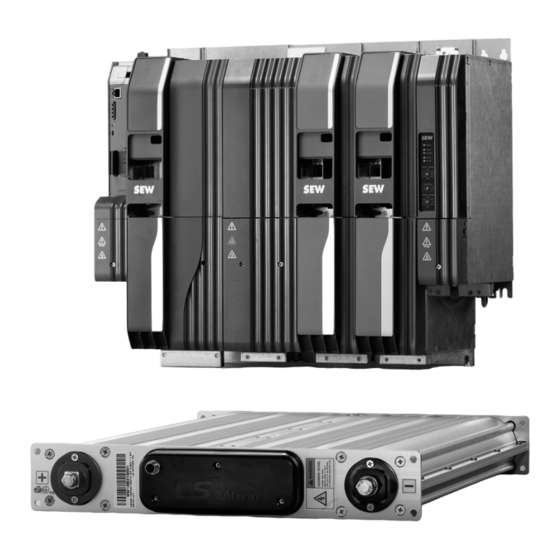
*26009471_0619* Drive Technology \ Drive Automation \ System Integration \ Services Operating Instructions ® MOVIDRIVE modular Power and Energy Solutions Power Supply for Multi-Axis systems with Storage Technology Edition 06/2019 26009471/EN... - Page 2 SEW-EURODRIVE—Driving the world...
-
Page 3: Table Of Contents
Table of contents Table of contents General information........................ 8 About this documentation .................... 8 Information on this documentation.................. 8 Structure of the safety notes ................... 9 1.3.1 Meaning of signal words ................ 9 1.3.2 Structure of section-related safety notes............ 9 1.3.3 Structure of embedded safety notes ............ 10 Rights to claim under limited warranty ................ 10 Other applicable documentation ................... 10 Product names and trademarks.................. 10... - Page 4 Table of contents Mechanical installation.................... 28 4.4.1 Minimum clearance and mounting position.......... 28 4.4.2 Mounting grid .................... 28 Electrical installation ..................... 30 4.5.1 Discharge times of the energy storage units.......... 31 4.5.2 General information.................. 31 4.5.3 Permitted voltage systems ................ 31 4.5.4 Use in IT systems..................
- Page 5 Table of contents 4.13.3 Electronics connection MDP92A power supply module....... 57 4.13.4 Electronics connection switched-mode power supply module with AC and DC supply MDS90A-.................. 58 Startup ............................. 59 General ......................... 59 5.1.1 Lifting applications.................. 59 5.1.2 Connecting power .................. 59 5.1.3 Connecting cables..................
- Page 6 Table of contents Fault responses ...................... 80 6.5.1 Default – fault response ................ 80 6.5.2 Parameterizable faults ................. 80 6.5.3 Module bus – fault transmission.............. 81 6.5.4 Module bus – emergency shutdown ............ 82 Fault module bus ...................... 83 6.6.1 Grid condition .................... 83 6.6.2 DC link condition ..................
- Page 7 Table of contents Accessories......................... 112 8.7.1 Thermal sensor for MDC90A .............. 112 Appendix .......................... 113 Abbreviation key ...................... 113 Index ............................ 115 Address list ........................... 118 Operating Instructions – Power and Energy Solutions...
-
Page 8: General Information
General information About this documentation General information About this documentation The current version of the documentation is the original. This documentation is an integral part of the product. The documentation is intended for all employees who perform work on the product. Make sure this documentation is accessible and legible. -
Page 9: Structure Of The Safety Notes
General information Structure of the safety notes Structure of the safety notes 1.3.1 Meaning of signal words The following table shows the grading and meaning of the signal words for safety notes. Signal word Meaning Consequences if disregarded DANGER Imminent hazard Severe or fatal injuries Possible dangerous situation Severe or fatal injuries... -
Page 10: Structure Of Embedded Safety Notes
General information Rights to claim under limited warranty 1.3.3 Structure of embedded safety notes Embedded safety notes are directly integrated into the instructions just before the de- scription of the dangerous action. This is the formal structure of an embedded safety note: SIGNAL WORD Type and source of hazard. -
Page 11: Safety Notes
Safety notes Preliminary information Safety notes Preliminary information The following general safety notes serve the purpose of preventing injury to persons and damage to property. They primarily apply to the use of products described in this documentation. If you use additional components, also observe the relevant warning and safety notes. -
Page 12: Target Group
Safety notes Target group Target group Specialist for me- Any mechanical work may be performed only by adequately qualified specialists. Spe- chanical work cialists in the context of this documentation are persons who are familiar with the design, mechanical installation, troubleshooting, and maintenance of the product who possess the following qualifications: •... -
Page 13: Designated Use
Safety notes Designated use Designated use The product is intended for control cabinet installation in electrical plants or machines. In case of installation in electrical systems or machines, startup of the product is pro- hibited until it is determined that the machine meets the requirements stipulated in the local laws and directives. -
Page 14: Installation/Assembly
Safety notes Installation/assembly Installation/assembly Ensure that the product is installed and cooled according to the regulations in the doc- umentation. Protect the product from strong mechanical strain. The product and its mounting parts must never protrude into the path of persons or vehicles. Ensure that components are not deformed and insulation spaces are not changed, particularly during transportation and handling. -
Page 15: Startup/Operation
Safety notes Startup/operation 2.10 Startup/operation Observe the safety notes in the chapters Startup and Operation in this documentation. Make sure the connection boxes are closed and screwed before connecting the sup- ply voltage. Depending on the degree of protection, products may have live, uninsulated, and sometimes moving or rotating parts, as well as hot surfaces during operation. -
Page 16: Device Structure
Device structure Nameplates Device structure Nameplates 3.1.1 MDP92A power supply module with controlled DC link voltage System nameplate 28497974667 Device status Serial number Performance data nameplate 28497969803 Device status Operating Instructions – Power and Energy Solutions... -
Page 17: Mdc90A Capacitor Module
Device structure Nameplates 3.1.2 MDC90A capacitor module System nameplate 28497972235 Device status Serial number Performance data nameplate 28497967371 Device status Operating Instructions – Power and Energy Solutions... -
Page 18: Switched-Mode Power Supply Module With Ac And Dc Supply Mds90A
Device structure Nameplates 3.1.3 Switched-mode power supply module with AC and DC supply MDS90A System nameplate 28576423435 Device status Serial number Performance data nameplate 28577015179 Device status Operating Instructions – Power and Energy Solutions... -
Page 19: Movidrive® Modular Power And Energy Solutions Type Code
Device structure MOVIDRIVE® modular Power and Energy Solutions type code MOVIDRIVE ® modular Power and Energy Solutions type code ® MOVIDRIVE modular Power and Energy Solutions type code Example: MDP92A-0250-503-4-S00 ® Product name • MD = MOVIDRIVE Device type • C = Capacitor module •... -
Page 20: Device Structure Of Mdp92A-0250-503-4-S00 Power Supply Module With Controlled Dc Link Voltage
Device structure Device structure of MDP92A-0250-503-4-S00 power supply module with controlled DC link voltage Device structure of MDP92A-0250-503-4-S00 power supply module with controlled DC link voltage 1 + TEMP R /NC 1 - TEMP R /NC X30 OUT unit X30 IN [16] [17] EC ID... -
Page 21: Device Structure Of Mdc90A-0120-50X-X-000 Capacitor Module
Device structure Device structure of MDC90A-0120-50X-X-000 capacitor module Device structure of MDC90A-0120-50X-X-000 capacitor module Power 28624631307 A: View from top B: View from front C: View from bottom Fastening for temperature LED display DC link voltage Terminal screw for TN/TT sensor systems X5: Connection +24 V supply... -
Page 22: Device Structure Of Mds90A-0540-5E3-X-000 Switched-Mode Power Supply Module With Ac And Dc Supply
Device structure Device structure of MDS90A-0540-5E3-X-000 switched-mode power supply module with AC and DC supply Device structure of MDS90A-0540-5E3-X-000 switched-mode power supply module with AC and DC supply [14] [15] Status Output Disable AC-IN DC-IN Output Voltage 24.8 24.4 25.2 24.0 25.6 26.8... -
Page 23: Installation
Installation Installation accessories Installation The devices from the Power and Energy Solutions series are exclusively intended for control cabinet installation according to their degree of protection. Installation accessories The listed standard accessories are included in the scope of delivery for the basic device. -
Page 24: Permitted Tightening Torques
Installation Permitted tightening torques Permitted tightening torques Screw connection Tightening torque in Nm MDP92A- MDC90A- MDS90A- 0250 0120 0540 Line connection 1.7 – 1.8 Braking resistor connection 1.7 – 1.8 3 – 4 3 – 4 3 – 4 DC link connection X4_A 3 –... -
Page 25: Requirements When Combining The Devices In A Network
Installation Requirements when combining the devices in a network Requirements when combining the devices in a network This chapter includes the conditions for using the devices and combination examples for the operating modes power mode and direct mode. The examples show the ar- rangement of the individual devices in the network. -
Page 26: Examples
Installation Requirements when combining the devices in a network 4.3.1 Examples Power mode MDM90A-.., MDP92A-.., to 4 MDC90A-.., axis modules (from left to right in descend- ing order of size). MDM90A MDP92A MDC90A MDA90A MDA90A MDS90A 28634005003 Operating Instructions – Power and Energy Solutions... - Page 27 Installation Requirements when combining the devices in a network Direct mode MDM90A-.., MDP92A-.., axis modules (from left to right in descending order of size). MDM90A MDP92A MDA90A MDA90A MDS90A 28635031819 Operating Instructions – Power and Energy Solutions...
-
Page 28: Mechanical Installation
Installation Mechanical installation Mechanical installation CAUTION Risk of injury to persons and damage to property. Never install defective or damaged application inverters. • Before installing modules, check them for external damage. Replace any dam- aged modules. NOTICE Risk of damage to property due to mounting surface with poor conductivity. Damage to the application inverter. -
Page 29: Mounting Grid
Installation Mechanical installation Mounting grid 27021610488337547 For dimension sheets of the devices, refer to chapter "Technical data". Operating Instructions – Power and Energy Solutions... -
Page 30: Electrical Installation
Installation Electrical installation Electrical installation DANGER There may be dangerous voltages inside the devices and at the terminal strips after the complete axis system has been disconnected from the power supply. Severe or fatal injuries from electric shock. To prevent electric shocks: •... -
Page 31: Discharge Times Of The Energy Storage Units
Installation Electrical installation INFORMATION Installation with protective separation. The application inverter meets all requirements for protective separation of power and electronics connections in accordance with EN 61800-5-1. The connected signal circuits and the DC 24 V voltage supply must meet the requirements according to SELV (Safety Extra Low Voltage) or PELV (Protective Extra Low Voltage) to ensure protective separation. -
Page 32: Use In It Systems
Installation Electrical installation 4.5.4 Use in IT systems To ensure IT system-capability, the terminal screw shown in the following figures must be removed from the bottom of the modules. MDP92A power supply module MDC90A capacitor module Switch-mode power supply module MDS90A INFORMATION EMC limit values No EMC limits are specified for interference emission in voltage supply systems... -
Page 33: Line Fuses, Fuse Types
Installation Electrical installation 4.5.5 Line fuses, fuse types Line fuses and miniature circuit breakers are used for fusing the supply system cables of the axis block. In case of a fault, these components protect the power supply module against short-circuits. For fusing, use fuses and miniature circuit breakers with the following properties: Type class Prerequisite... -
Page 34: Power Connections
Installation Electrical installation 4.5.7 Power connections ® For information on this topic, refer to the "MOVIDRIVE modular Application Inverters" operating instructions. 4.5.8 Special aspects when connecting an external storage unit If an external storage unit that is not installed in the control cabinet is connected to the connection X4_B of the MDP92A power supply module, a ferrite must be attached to the connection cables, see the following figure. - Page 35 Installation Electrical installation Settings on the selector switches of the MDS90A Status Output Disable AC-IN DC-IN Output Voltage 24.8 24.4 25.2 24.0 25.6 26.8 26.0 26.4 Start Delay Starting Voltage 28675019787 [1] Output voltage [2] Start delay [3] Starting voltage Output voltage The 24 V nominal output voltage can be increased in steps of 0.2 V up to 27 V.
-
Page 36: Connection Of An Axis System
Installation Electrical installation Using 3 or more switched-mode power supply modules If 3 or more MDS90A switched-mode power supply modules are used, note that only 2 modules may be connected to the DC 24 V bars. The 2 modules that are connected in parallel must not be connected to the other MDS90A modules, neither by a busbar nor by any other connection. -
Page 37: Installing Touch Guards And Closing Covers
Installation Electrical installation 4.5.11 Installing touch guards and closing covers All modules of the application inverter are equipped with touch guards [1] and the outer modules of the axis system have closing covers [2], see the following figure. If the axis system contains a master module, the closing cover [2] only needs to be at- tached at the last module in the axis system. - Page 38 Installation Electrical installation Without master module 18014412466136331 Touch guard Closing cover Reinstall all touch guards [1] after installation work. 1. Insert the closing cover [2] into the touch guard [1]. 2. Install the touch guard [1] on the respective module. Insert the screws and tighten them securely with the specified tightening torque.
-
Page 39: Output Brake Chopper
Installation Electrical installation 4.5.12 Output brake chopper NOTICE Connecting capacitive or inductive loads to the power supply module. Destruction of the power supply module. • Only connect ohmic loads (braking resistors). • Never connect capacitive or inductive loads. 4.5.13 Inputs/outputs NOTICE Damage to the digital inputs and digital outputs. - Page 40 Installation Electrical installation The connectors of the module bus cables are red and black to simplify correct installa- tion. • The black connectors must be plugged into the bus input X30 IN. • The red connectors must be plugged into the bus output X30 OUT. System bus cable The 4-pole system bus cable is used between automation components, see the follow- ing figure.
-
Page 41: Braking Resistors
Installation Braking resistors Braking resistors 4.6.1 Protection of braking resistor against thermal overload External thermal circuit breaker TCB MDP92A power supply module If an external TCB thermal circuit breaker is used, the following connection applies. Connection MDP92A X7:2 -Temp_R X7:1 +Temp_R 23 24 1 4 3 6 25766602891... -
Page 42: Line Contactor
Installation Line contactor Line contactor A line contactor is used for galvanic separation of the axis system and the supply sys- tem. The separation from the grid is necessary for electrical work on the axis system, for example. DANGER The integrated lock of the DC/DC converter for MDP92A power supply modules does not galvanically separate the axis block from the grid and therefore does not de-energize it. -
Page 43: Connecting The Discharge Unit
Installation Connecting the discharge unit Connecting the discharge unit 4.8.1 Connection variant 1 With connection variant 1, the discharge unit is connected to the MDP92A power sup- ply module using the TCB thermal circuit breaker. X1 L1 L2 L3 MDC90A MDP92A X4_B X4_B... -
Page 44: Connection Variant 3
Installation Connecting the discharge unit 4.8.2 Connection variant 2 With connection variant 2, the discharge unit is connected to the MDC90A capacitor module using the TCB thermal circuit breaker. X1 L1 L2 L3 MDC90A MDP92A X4_B X4_B U V W 1 4 3 6 28892008715 TCB thermal circuit breaker... -
Page 45: Accessories
Installation Connecting the discharge unit 4.8.3 Connection Variant 3 With connection variant 3, the discharge unit is connected to the DC link busbar of the last axis module MDA/MDD using the TCB thermal circuit breaker. X1 L1 L2 L3 MDC90A MDP92A X4_B X4_B... -
Page 46: Line Filter
Installation Line filter Line filter • Install the line filter close to the power supply module/application inverter but out- side the minimum clearance for cooling. The line filter must not be heated by the exhaust air of the power supply module/application inverter. •... -
Page 47: Temperature Monitoring Mdc90A Capacitor Module
Installation Temperature monitoring MDC90A capacitor module 4.10 Temperature monitoring MDC90A capacitor module The mounting panel with the installed sensor is screwed to the intended position at the top of the device, see chapter "Device structure of MDC90A-0120-50X-X-000 capa- citor module" (→ 2 21). Due to the position of the temperature sensor at the housing, a difference of approx. -
Page 48: Emc-Compliant Installation
Installation EMC-compliant installation 4.11 EMC-compliant installation [15] RUN ERR RUN ERR [11] [10] [13] [16] [16] [16] [12] [10] [16] 19501899787 Zinc-coated mounting plate [9] Braking resistor performance Line filter [10] Motor cable MDP power supply module [11] Power shield plate at the axis module PE busbar [12] Brake cable HF connection of PE busbar/mounting plate... -
Page 49: Control Cabinet
Installation EMC-compliant installation The information in this chapter will help you to optimize the system in regard of elec- tromagnetic compatibility, or to eliminate already existing EMC interferences. The notes in this chapter are not legal regulations; they are merely recommendations for improving the electromagnetic compatibility of your plant. -
Page 50: Line Filter Connection
Installation EMC-compliant installation 4.11.5 Line filter connection Limit the length of the connection lead between the line filter and the inverter to the absolute minimum needed. You must never route filtered and unfiltered cables together. For this reason, route in- coming and outgoing line filter cables separately. -
Page 51: Terminal Assignment
Installation Terminal assignment 4.12 Terminal assignment 4.12.1 Power supply module with controlled DC link voltage MDP92A-0250-503-4-000 Representa- Terminal Connection Brief description tion X1_1 Voltage B-side X1_2 Reserved +UZB X1_3 Braking resistor connection MDP92A-0250-503-4-000 X1_4 X1_5 X1_6 Line connection MDP92A-0250-503-4-000 X1_7 PE connection X4: +U DC link connection... - Page 52 Installation Terminal assignment Representa- Terminal Connection Brief description tion X20_1 +24 V DC 24 V voltage supply X20_2 DOR-C Digital output 5, isolated contact, freely programmable X20_3 DOR-NO X20_4 DO03 Digital output 4, freely programmable X20_5 DO02 Digital output 3, freely programmable X20_6 DO01 Digital output 2, freely programmable...
-
Page 53: Mdc90A-0120-50X-X-000 Capacitor Modules
Installation Terminal assignment 4.12.2 MDC90A-0120-50X-X-000 capacitor modules Representa- Terminal Connec- Brief description tion tion X4:+U DC link connection X4:-U PE connection X4_B:+ Connection DC link (output) X4_B:- PE connection X5:24 V 24 V 24 V +24 V supply voltage X5:GND Operating Instructions – Power and Energy Solutions... - Page 54 Installation Terminal assignment 4.12.3 Switched-mode power supply module with AC and DC supply MDS90A-0540-5E3-X-000 Representa- Terminal Connec- Brief description tion tion X1_1 X1_2 Connection AC supply X1_3 PE connection X4:+U DC link connection X4:-U PE connection X5_A: 24 V DC output (busbar) 24 V 24 V X5_A:...
-
Page 55: Wiring Diagrams
Installation Wiring diagrams 4.13 Wiring diagrams 4.13.1 Wiring of MDS90A with MDC90A via MDP92A L1 L2 L3 L1 ´ L2 ´ L3 ´ +UZB MDS90A MDP92A MDC90A X5_A X4_B X4_B X2_1 X2_2 28862015115 [1] Line filter [2] Braking resistor connection [3] Motor Operating Instructions –... -
Page 56: Wiring Of Mds90A And Mdp92A With Mdc90A With Separate Line Connection
Installation Wiring diagrams 4.13.2 Wiring of MDS90A and MDP92A with MDC90A with separate line connection L1 L2 L3 L1 ´ L2 ´ L3 ´ L1 L2 L3 +UZB MDS90A MDP92A MDC90A X5_A X4_B X4_B X2_1 X2_2 28862017547 [1] Line contactor (optional) [2] Line filter [3] NC contact contactor [4] Braking resistor connection... -
Page 57: Electronics Connection Mdp92A Power Supply Module
Installation Wiring diagrams 4.13.3 Electronics connection MDP92A power supply module DC 24 V auxiliary voltage output +24 V Shared relay contact DOR-C NO contact DOR-NO Freely programmable DO03 + T emp_R Freely programmable DO02 -T emp_R Freely programmable DO01 reserviert Freely programmable DO00 reserviert... -
Page 58: Electronics Connection Switched-Mode Power Supply Module With Ac And Dc Supply Mds90A
Installation Wiring diagrams 4.13.4 Electronics connection switched-mode power supply module with AC and DC supply MDS90A-.. Analog signal output current (4 – 20 mA) 24 V Monitor Analog signal UZ input current (4 – 20 mA) DCLink Monitor Digital output, output voltage OK Output OK Reference potential for digital outputs GND_S... -
Page 59: Startup
Startup General Startup ® The startup of the devices is performed using the engineering software "MOVISUITE for Power and Energy Solutions". Contact your SEW-EURODRIVE contact person to get the engineering software. General DANGER Uncovered power connections. Severe or fatal injuries from electric shock. •... -
Page 60: Connecting Cables
Startup Assigning the EtherCAT®/SBusPLUS address at the power supply module 5.1.3 Connecting cables NOTICE Disconnecting lines under voltage. Irreparable damage to the application inverter or unforeseeable malfunctions. • The following plug-in connections must always be disconnected in a de-ener- gized state: Motor, grid, braking resistor, brake, encoder, connection, energy storage unit, connection discharge unit. -
Page 61: Startup Requirements
Startup Startup requirements Startup requirements The following prerequisites apply to startup: • You have performed a correct project planning for the used devices. • You have installed the device correctly both mechanically and electrically. • Safety measures prevent accidental drive startup. •... -
Page 62: Startup Procedure
Startup Startup procedure Startup procedure ® The devices are put into operation using the MOVISUITE engineering software from SEW‑EURODRIVE. 15643252491 The startup procedure is divided into segments. The following steps illustrate an ex- ample of the startup procedure for a power supply module. Functions segment Inputs/outputs •... -
Page 63: Check List For Startup
Startup Startup procedure 5.4.1 Check list for startup The following checklist lists the necessary steps for complete startup. Step Startup step Finished ® Install the MOVI-C component ® Start MOVISUITE (until July 2019 version SR2.2) Parameterize the monitoring functions and limit values Parameterize setpoints and FCBs Configure digital inputs and outputs Configuring process data... -
Page 64: Operation
Operation 7-segment display Operation 7-segment display 6.1.1 Operating displays • The two 7-segment displays indicate the operating state of the power supply module. 6.1.2 Fault display The power supply module detects any faults that occur and displays them as fault code. -
Page 65: Operating Displays
Operation Operating displays Operating displays 6.2.1 Operating displays capacitor module – LED displays The voltage state of the DC link is displayed by a green LED. The LED displays the voltage level using different flashing frequencies. DC link voltage U Flashing frequency of the LED DC 50 V 0.4 Hz... - Page 66 Operation Operating displays Display Description State Comment / action Output stage inhibit • Output stage is inhibited. The output stage is inhibited. Brake chopper is still working Inhibit brake chopper • The brake chopper is inhibited Output stage and brake chopper are inhibited •...
-
Page 67: Operating Displays Switched-Mode Power Supply Module - Led Displays
Operation Operating displays 6.2.3 Operating displays switched-mode power supply module – LED displays Status Output Disable AC-IN DC-IN Output Voltage 24.8 24.4 25.2 24.0 25.6 26.8 26.0 26.4 Start Delay Starting Voltage + UZ 28616477707 Color Meaning Green Device is supplied and ready for operation Status LED [1] Internal device faults or overheating LED display [2]... -
Page 68: Fault Description
Operation Fault description Fault description 6.3.1 Fault 1 Output stage monitoring Subfault: 1.2 Description: Overcurrent in output stage Response: Emergency stop + output stage inhibit Cause Measure Motor current too high. Connect a smaller motor. Current supply. Check the current supply. Current transformer Check the current transformer. -
Page 69: Fault 7 Dc Link
Operation Fault description 6.3.4 Fault 7 DC link Subfault: 7.6 Description: Overvoltage A-or B-side Response: Output stage inhibit Cause Measure Excessive regenerative power of an actuator. Check the application. Energy storage unit dimensioned too small. Check the project planning. Excessive recharging power from grid. Check the application. -
Page 70: Fault 11 Temperature Monitoring
Operation Fault description Subfault: 10.7 Description: Calculation result of multiplication/division command too large Response: Emergency stop + output stage inhibit Cause Measure Calculation result of multiplication/division command exceeds Check the program. 32 bits. Failed to write calculation result of multiplication/division com- Check the program. -
Page 71: Fault 16 Startup
Operation Fault description 6.3.7 Fault 16 Startup Subfault: 16.30 Description: Faulty EtherCAT® EEPROM configuration state Response: Warning Cause Measure Faulty EtherCAT®/SBusPLUS EEPROM configuration status. Contact SEW-EURODRIVE Service. EEPROM not loaded; binary file not loaded. Faulty EEPROM loading procedure. Contact SEW-EURODRIVE Service. Faulty EEPROM checksum. -
Page 72: Fault 19 Process Data
Operation Fault description Subfault: 18.12 Description: Configuration data Response: Emergency stop + output stage inhibit System state: Fault acknowledgment with CPU reset Cause Measure Configuration data not plausible or cannot be interpreted by ac- Update the firmware or load valid configuration data. tive firmware version. -
Page 73: Fault 25 Parameter Memory Monitoring
Operation Fault description 6.3.13 Fault 25 Parameter memory monitoring Subfault: 25.2 Description: NV memory – runtime error Response: Emergency stop + output stage inhibit Cause Measure Runtime error of non-volatile memory system. – Reset the device. – If this occurs repeatedly, replace device. Contact SEW- EURODRIVE Service. -
Page 74: Fault 26 External Fault
Operation Fault description Subfault: 25.19 Description: Control electronics QA data – CRC error Response: Warning Cause Measure Faulty quality assurance data of control electronics. Contact SEW-EURODRIVE Service. Subfault: 25.20 Description: Initialization error – basic device memory Response: Emergency stop + output stage inhibit Cause Measure Initialization error of the basic device memory. -
Page 75: Fault 32 Communication
Operation Fault description 6.3.15 Fault 32 Communication Subfault: 32.2 Description: EtherCAT®/SBusPLUS process data timeout Response: Fieldbus – timeout response Cause Measure Process data timeout during EtherCAT®/SBusPLUS communi- – Check the wiring of the system bus and module bus. cation. – Check that the EtherCAT®/SBusPLUS configuration is cor- rectly set in the MOVI-C®... -
Page 76: Fault 34 Process Data Configuration
Operation Fault description Subfault: 33.12 Description: Memory module plugged in Response: Emergency stop + output stage inhibit Cause Measure A plugged-in memory module was detected during device start. – Switch off the device. Remove the memory module and re- The setting for the device parameter source is set to "Internal start the device. -
Page 77: Fault 47 Supply Unit
Operation Fault description Subfault: 35.4 Description: Technology level – invalid activation key Response: Emergency stop + output stage inhibit Cause Measure The activation key was entered incorrectly. Enter the activation key again. The activation key was not created for this device. Check the activation key. -
Page 78: Fault 81 Storage Bundle
Operation Fault description Subfault: 48.5 Description: Change of module bus configuration Response: Emergency stop + output stage inhibit System state: Fault acknowledgment with CPU reset Cause Measure The module bus configuration has been changed. The device Acknowledge the fault. The unit reboots. must be restarted. -
Page 79: Responses To Fault Acknowledgment
Operation Responses to fault acknowledgment Responses to fault acknowledgment 6.4.1 Fault acknowledgment at the power supply module During fault acknowledgment, the final fault status determines which reset type will be executed, see following table. If the power supply module is configured as module bus master, the faults are trans- ferred to the module bus slaves, see chapter "Module bus –... -
Page 80: Fault Responses
Operation Fault responses Fault responses 6.5.1 Default – fault response Fault response Description No response The power supply module ignores the event. The power supply module sends a warning message with self-reset. The fault is automatically Warning with self-reset reset after the cause of fault is eliminated. Warning The power supply module issues a warning message. -
Page 81: Module Bus - Fault Transmission
Operation Fault responses 6.5.3 Module bus – fault transmission The module bus master sends all fault codes, subfault codes, fault messages and the type of the fault that occur to all connected module bus slaves using the module bus. The fault processing in the slave only evaluates the type of the fault. Fault code and subfault code serve only as information. -
Page 82: Module Bus - Emergency Shutdown
Operation Fault responses 6.5.4 Module bus – emergency shutdown With system conditions that may damage or destroy the devices, it is important that the output stages of the devices can be inhibited quickly. The module bus master has an emergency shutdown function that is triggered with critical faults. Each station may activate the emergency shutdown. -
Page 83: Fault Module Bus
Operation Fault module bus Fault module bus The module bus master sends all occurring fault messages to the connected module bus stations (slaves) using the module bus. The faults are divided into 3 categories (warning, standard fault, critical fault). There are two fault transmission modes (nor- mal, warning) available, see chapter "Module bus –... -
Page 84: Power Supply Monitoring
Operation Power supply monitoring Power supply monitoring Power supply monitoring comprises the following functions: supply system monitoring, rapid undervoltage detection and DC link monitoring. 6.7.1 Supply system monitoring Line frequency The line frequency of the connected AC grid must be set correctly so that the line voltages can be measured correctly. -
Page 85: Rapid Undervoltage Detection
Operation Power supply monitoring 6.7.2 Rapid undervoltage detection The voltage on the output stage of the A- or B-side is monitored. Monitoring is started in an interval of 0.5 ms. If this monitoring detects a grid as "ON", the respective bit is set in the parameter "8809.24 grid condition". -
Page 86: Dc Link Monitoring
Operation Power supply monitoring 6.7.3 DC link monitoring Monitoring is started in an interval of 1 ms. The grid is monitored by means of the DC voltages of the A-side and/or B-side depending on the setting. With DC link monitoring, no fault is triggered. The device changes its status from "Ready"... -
Page 87: Service
Service Electronics Service by SEW‑EURODRIVE Service Electronics Service by SEW‑EURODRIVE If you are unable to rectify a fault, contact SEW‑EURODRIVE Service. For the ad- dresses, refer to www.sew‑eurodrive.com. When contacting SEW‑EURODRIVE Service, always specify the following information so that our service personnel can assist you more effectively: •... -
Page 88: Shutdown
Service Shutdown Shutdown Voltage from charged capacitors can still be present at the live components or power connections after disconnection from the supply voltage. Observe the following inform- ation to avoid electric shock and risk of injury: WARNING The energy storage units are still charged after the device has been switched off. Severe or fatal injuries from electric shock. -
Page 89: Discharging The Energy Storage Units Using The Discharge Unit
Service Discharging the energy storage units using the discharge unit Discharging the energy storage units using the discharge unit A requirement for discharging the energy storage units using the discharge unit is the installation with the DCP21A cable set and further accessories depending on the con- nection variant. -
Page 90: Connection Variant 3
Service Discharging the energy storage units using the discharge unit 7.4.2 Connection variant 2 With connection variant 2, the discharge unit is connected to the MDC90A capacitor module using the TCB thermal circuit breaker. X1 L1 L2 L3 MDC90A MDP92A X4_B X4_B U V W... -
Page 91: Accessories
Service Discharging the energy storage units using the discharge unit 7.4.3 Connection Variant 3 With connection variant 3, the discharge unit is connected to the DC link busbar of the last axis module MDA/MDD using the TCB thermal circuit breaker. X1 L1 L2 L3 MDC90A MDP92A... -
Page 92: Discharging The Energy Storage Units Using The Braking Resistor
Service Discharging the energy storage units using the braking resistor Discharging the energy storage units using the braking resistor The device has a connection on the A-side for installing an external discharge resistor. It is controlled by the internal brake chopper and can be used to discharge the DC cir- cuit that is connected to the A-side. -
Page 93: Waste Disposal
Service Waste disposal Waste disposal Observe the applicable national regulations. Dispose of the following materials separately in accordance with the country-specific regulations in force, such as: • Electronics scrap (printed circuit boards) • Plastic • Sheet metal • Copper • Aluminum This product falls within the scope of the European WEEE Directive 2012/19/EU on waste electrical and electronic equipment. -
Page 94: Technical Data
Technical data Markings Technical data Markings 8.1.1 Basic device The modules of the Power and Energy Solutions series meet the following regulations and guidelines: Mark Definition The CE mark states the compliance with the following European guidelines: • Low Voltage Directive 2014/35/EU •... - Page 95 Technical data Markings NF.. line filter Mark Definition The CE mark states the compliance with the following European guidelines: • Directive 2011/65/EU for limiting the use of hazardous substances in electric and electronic equipment The China RoHS mark states compliance with directive SJ/T 11364-2014 for limiting the use of hazardous substances in electric and electronic equipment.
-
Page 96: General Technical Data
Technical data General technical data General technical data The following table lists the technical data for all modules of the Power and Energy Solutions series independent of • Type • Design • Size • Performance Power and Energy Solutions Interference immunity Meets EN 61800-3;... -
Page 97: Mdp92A Power Supply Module With Controlled Dc Link Voltage
Technical data MDP92A power supply module with controlled DC link voltage MDP92A power supply module with controlled DC link voltage 8.3.1 Performance data ® MOVIDRIVE modular MDP92A-0250-503-4-S00 Size Nominal power P 25 kW Input Nominal line voltage (to EN 50160) AC U 3 ×... -
Page 98: Electronics Data - Signal Terminals
Technical data MDP92A power supply module with controlled DC link voltage 8.3.2 Electronics data – signal terminals Terminal designa- Specifications tion General Design In accordance with IEC 61131-2 Supply voltage Connection DC 24 V -10%, +20% to EN 61131 Connection contacts CU bars 2 x 5 mm², M4 screw fitting Braking resistor temperature monitoring Evaluation of temperature sensor at X7: 1... -
Page 99: Dimension Drawings
Technical data MDP92A power supply module with controlled DC link voltage 8.3.3 Dimension drawings 28547711499 Operating Instructions – Power and Energy Solutions... -
Page 100: Mdc90A Capacitor Module
Technical data MDC90A capacitor module MDC90A capacitor module 8.4.1 Performance data Capacitor module MDC90A-0120-50X-X-000 Size DC link connection Nominal DC link voltage U (according to EN 50160) DC 560 V line Operating voltage range (according to EN 50160) DC 0 V – 800 V Maximum voltage DC 900 V Nominal capacitance... -
Page 101: Dimension Drawings
Technical data MDC90A capacitor module 8.4.2 Dimension drawings 28547709067 Operating Instructions – Power and Energy Solutions... -
Page 102: Switched-Mode Power Supply Module With Ac And Dc Supply Mds90A
Technical data Switched-mode power supply module with AC and DC supply MDS90A Switched-mode power supply module with AC and DC supply MDS90A 8.5.1 Performance data Switched-mode power supply module with AC and DC MDS90A-0540-5E3-X-000 supply Size Input (DC link side and supply system) Operating voltage range (according to EN 50160) DC 150 V – 800 V AC 1 ×... -
Page 103: Electronics Data - Signal Terminals
Technical data Switched-mode power supply module with AC and DC supply MDS90A 8.5.2 Electronics data – signal terminals Electronics data Terminal Connection Plug connector 1 core: 0.14 – 1.5 mm Digital inputs X9_7 • Low level: 0 – 12.5 V •... -
Page 104: Dimension Drawings
Technical data Switched-mode power supply module with AC and DC supply MDS90A 8.5.3 Dimension drawings 28547713931 Operating Instructions – Power and Energy Solutions... -
Page 105: Technical Data Of The Braking Resistors And Filters
Technical data Technical data of the braking resistors and filters Technical data of the braking resistors and filters 8.6.1 Braking resistors type BW.../BW...-T General The BW... / BW...-T braking resistors are adapted to the technical characteristics of the application inverter. Braking resistors with different continuous and peak braking powers are available. - Page 106 Technical data Technical data of the braking resistors and filters Technical data and assignment to an inverter Technical data Braking resistor Unit BW047-002 BR047-010-T BR027-016-T BW027-024-T Part number 08281661 17983207 17983215 17983231 Nominal power P Resistance value R Ω 47 ±10% 47 ±10% 27 ±...
- Page 107 Technical data Technical data of the braking resistors and filters Dimension drawings and dimensions Wire resistor M../PG.. M../PG.. 18874863883 Cable entry is possible from both sides. Braking resistor Main dimensions in mm Mounting dimensions in mm Cable gland BW47-010-T M25+M12 BW027-016-T M25+M12 BW027-024-T...
- Page 108 Technical data Technical data of the braking resistors and filters Braking resistor Main dimensions in mm Mounting dimensions in mm Cable gland BW047-002 Touch guard BS.. Description A BS.. touch guard is available for braking resistors in flat design. Touch guard BS005 Part number 0813152X...
-
Page 109: Tcb Thermal Circuit Breaker Option
Technical data Technical data of the braking resistors and filters 8.6.2 TCB thermal circuit breaker option General The TCB thermal circuit breaker protects the braking resistor from constant overload and protects in case of a short circuit in the cable or the braking resistor. The setting range of the thermal circuit breaker has to be selected in such a way that it corresponds to the tripping current I of the braking resistor. - Page 110 Technical data Technical data of the braking resistors and filters Dimension drawing 17195255435 Operating Instructions – Power and Energy Solutions...
-
Page 111: Line Filter
Technical data Technical data of the braking resistors and filters 8.6.3 Line filter Line filters are used to suppress interference emission on the line side of inverters. UL and cUL approval The listed line filters have cRUus approvals independent of the application inverter. Technical data Line filter NF0420-513... -
Page 112: Accessories
Technical data Accessories Accessories 8.7.1 Thermal sensor for MDC90A The capacitor module can be monitored using a PT1000 temperature sensor. By using a PT1000 temperature sensor, you can protect the device from excessive load, which, as a result, leads to a longer service life of the energy storage unit. Monitoring is per- ®... -
Page 113: Appendix
Appendix Abbreviation key Appendix Abbreviation key The following table lists the abbreviations that are used in this document together with their unit and meaning. Abbreviation Information on Unit Meaning the nameplate Asynchronous motor μF Capacitance Maximum output frequency Line frequency line Frequency of the pulse width modulation Installation altitude... - Page 114 Appendix Abbreviation key Abbreviation Information on Unit Meaning the nameplate DC 24 V to supply STO_P1 and STO_P2 Supply voltage of encoders DC 12 V supply voltage of encoders S12VG DC 24 V supply voltage of encoders S24VG Voltage supply for electronics and brake ϑ °C Ambient temperature (+ES) ...
-
Page 115: Index
Index Index Permitted voltage systems ...... 31 Safety notes ........... 14 Abbreviation key .......... 113 Use in IT systems........... 32 Accessories Electronics connection MDP92A ...... 57 Thermal sensor .......... 112 Electronics connection MDS90A ...... 58 ® Assigning the EtherCAT /SBusPLUS address.. 60 Electronics Service .......... - Page 116 Index Temperature monitoring MDC90A .... 47 Responses to fault acknowledgment.... 79 Terminal assignment ........ 51 Safety notes ........... 15 Wiring diagrams .......... 55 Installing touch guards and closing covers.. 37 Permitted tightening torques ....... 24 IT systems ............ 32 Permitted voltage systems ........ 31 Product names ............
- Page 117 Index ® System bus EtherCAT /SBusPLUS .... 39 MDS90A ............ 54 Thermal sensor .......... 112 Tightening torques.......... 24 Target group ............ 12 Trademarks ............ 10 TCB thermal circuit breaker......... 41 Transport ............. 13 Technical data Type code............ 19 General technical data ........ 96 Line filter............
-
Page 118: Address List
Address list Address list Argentina Assembly Buenos Aires SEW EURODRIVE ARGENTINA S.A. Tel. +54 3327 4572-84 Sales Ruta Panamericana Km 37.5, Lote 35 Fax +54 3327 4572-21 (B1619IEA) Centro Industrial Garín http://www.sew-eurodrive.com.ar Prov. de Buenos Aires sewar@sew-eurodrive.com.ar Australia Assembly Melbourne SEW-EURODRIVE PTY. - Page 119 Address list Cameroon Sales Douala SEW-EURODRIVE S.A.R.L. Tel. +237 233 39 02 10 Ancienne Route Bonabéri Fax +237 233 39 02 10 P.O. Box sew@sew-eurodrive-cm B.P 8674 Douala-Cameroun Canada Assembly Toronto SEW-EURODRIVE CO. OF CANADA LTD. Tel. +1 905 791-1553 Sales 210 Walker Drive Fax +1 905 791-2999...
- Page 120 Address list Colombia Assembly Bogota SEW-EURODRIVE COLOMBIA LTDA. Tel. +57 1 54750-50 Sales Calle 17 No. 132-18 Fax +57 1 54750-44 Service Interior 2 Bodega 6, Manzana B http://www.sew-eurodrive.com.co Santafé de Bogotá sew@sew-eurodrive.com.co Croatia Sales Zagreb KOMPEKS d. o. o. Tel.
- Page 121 Address list France Assembly Bordeaux SEW-USOCOME Tel. +33 5 57 26 39 00 Sales Parc d'activités de Magellan Fax +33 5 57 26 39 09 Service 62 avenue de Magellan – B. P. 182 33607 Pessac Cedex Lyon SEW-USOCOME Tel. +33 4 74 99 60 00 75 rue Antoine Condorcet Fax +33 4 74 99 60 15 38090 Vaulx-Milieu...
- Page 122 Address list Germany SEW-EURODRIVE GmbH & Co KG Tel. +49 7348 9885-0 Dieselstraße 18 Fax +49 7348 9885-90 89160 Dornstadt dc-ulm@sew-eurodrive.de Würzburg SEW-EURODRIVE GmbH & Co KG Tel. +49 931 27886-60 Nürnbergerstraße 118 Fax +49 931 27886-66 97076 Würzburg-Lengfeld dc-wuerzburg@sew-eurodrive.de Drive Service Hotline / 24 Hour Service 0 800 SEWHELP 0 800 7394357...
- Page 123 Address list Indonesia Jakarta PT. Agrindo Putra Lestari Tel. +62 21 2921-8899 JL.Pantai Indah Selatan, Komplek Sentra In- Fax +62 21 2921-8988 dustri Terpadu, Pantai indah Kapuk Tahap III, aplindo@indosat.net.id Blok E No. 27 http://www.aplindo.com Jakarta 14470 Surabaya PT. TRIAGRI JAYA ABADI Tel.
- Page 124 Address list Lebanon Sales (Jordan, Kuwait , Beirut Middle East Drives S.A.L. (offshore) Tel. +961 1 494 786 Saudi Arabia, Syria) Sin El Fil. Fax +961 1 494 971 B. P. 55-378 http://www.medrives.com Beirut info@medrives.com Lithuania Sales Alytus UAB Irseva Tel.
- Page 125 Fax +595 21 3285539 Departamento Central sewpy@sew-eurodrive.com.py Fernando de la Mora, Barrio Bernardino Peru Assembly Lima SEW EURODRIVE DEL PERU S.A.C. Tel. +51 1 3495280 Sales Los Calderos, 120-124 Fax +51 1 3493002 Service Urbanizacion Industrial Vulcano, ATE, Lima http://www.sew-eurodrive.com.pe sewperu@sew-eurodrive.com.pe...
- Page 126 Address list Senegal Sales Dakar SENEMECA Tel. +221 338 494 770 Mécanique Générale Fax +221 338 494 771 Km 8, Route de Rufisque http://www.senemeca.com B.P. 3251, Dakar senemeca@senemeca.sn Serbia Sales Belgrade DIPAR d.o.o. Tel. +381 11 347 3244 / +381 11 288 0393 Ustanicka 128a Fax +381 11 347 1337 PC Košum, IV floor office@dipar.rs 11000 Beograd...
- Page 127 Address list Spain Assembly Bilbao SEW-EURODRIVE ESPAÑA, S.L. Tel. +34 94 43184-70 Sales Parque Tecnológico, Edificio, 302 http://www.sew-eurodrive.es Service 48170 Zamudio (Vizcaya) sew.spain@sew-eurodrive.es Sri Lanka Sales Colombo SM International (Pte) Ltd Tel. +94 1 2584887 254, Galle Raod Fax +94 1 2582981 Colombo 4, Sri Lanka Swaziland Sales...
- Page 128 Address list United Arab Emirates Drive Technology Dubai SEW-EURODRIVE FZE Tel. +971 (0)4 8806461 Center PO Box 263835 Fax +971 (0)4 8806464 Jebel Ali Free Zone – South, info@sew-eurodrive.ae P.O. Box Dubai, United Arab Emirates Uruguay Assembly Montevideo SEW-EURODRIVE Uruguay, S. A. Tel.
- Page 132 SEW-EURODRIVE—Driving the world SEW-EURODRIVE GmbH & Co KG Ernst-Blickle-Str. 42 76646 BRUCHSAL GERMANY Tel. +49 7251 75-0 Fax +49 7251 75-1970 sew@sew-eurodrive.com www.sew-eurodrive.com...
Need help?
Do you have a question about the MOVIDRIVE MDC90A-0120-50X-X-000 and is the answer not in the manual?
Questions and answers