
Subscribe to Our Youtube Channel
Related Manuals for Mitsubishi LE-30CTN


Summary of Contents for Mitsubishi LE-30CTN
- Page 1 ZJ -4049D LE-30CTN MODEL (Conforming to CE Marking) INSTRUCTION MANUAL JZ990D33401D...
- Page 3 We shall not be responsible for any damage caused by repair, disassembly, modification, etc. performed by a third party other than MITSUBISHI or a company specified by MITSUBISHI. The cautions on safety and the specifications described in the instruction manual are subject to change without...
- Page 5 Note: This instruction manual describes how to handle the tension controller LE-30CTN. Read this manual and manuals of relevant products before using the LE-30CTN, understand sufficiently the specifications of all products, and use them correctly. See to it that this manual is delivered to the end user.
-
Page 6: Conformity To Standards
For example, tension controllers are required not to cause electrical shock, fire and injury. Conformity to EC Directives (CE marking) The CE marking does not assure that the entire mechanical system manufactured using the LE-30CTN conforms to the following directives. -
Page 7: Iso International Standard [ Iso 9001 ] For Quality Assurance
(*1) We recommend a control box in conformity to the EMC Directive. 2) Cautions on connection of tension detector and actuator The LE-30CTN has analog inputs and outputs, and is sensitive to noise. It should be handled and installed carefully. -
Page 8: Table Of Contents
Table of Contents Conformity to Standards ..................4 EN standard: Conformity to EC Directives/CE marking ............4 ISO International Standard [ ISO 9001 ] for quality assurance ..........5 Table of Contents ....................6 1. Outline ........................9 1.1 Features ..........................9 1.2 Panel configuration ...................... - Page 9 5.2 Output setting for stoppage ....................27 5.2.1 Switching between manual output 1 and 2 ................27 5.2.2 Output memory function ......................27 5.2.3 Switching between manual output value and memory value ........... 28 5.3 Correction for acceleration and deceleration ..............28 5.3.1 Functions of gain 1 and gain 2 ....................
- Page 10 9. To Use AC Servomotor ..................43 10. To Use two-reel switching ................44 11. Inspection and Maintenance ................45 11.1 Initial inspection ......................45 11.1.1 Confirmation of selection ......................45 11.1.2 Operation sequence check ..................... 45 11.1.3 Wiring check ........................... 45 11.2 Maintenance ........................
-
Page 11: Outline
1.1 Features Outline The LE-30CTN tension controller receives signal from the LX-TD or LX-TD-909 tension detector to automatically control the tension of the long material at the unwinder, feed reel, and winder. This controller therefore generates a control voltage of 0 to 24 V to control the powder clutch/brake and the hysteresis clutch/... -
Page 12: Panel Configuration
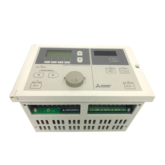
1. Outline 1.2 Panel configuration Panel configuration (7)Monitor display (6)Screen selection keys (8)Unit of monitoring item (5)LCD display (9)Monitor item selection key (10)MANUAL indicator LED (4)Function keys (11)AUTO indicator LED (3)Power indicator (12)Automatic control mode key (13)Manual control mode key (2)Keyin LED (14)Output ON/OFF LED (1)Keyin key... -
Page 13: Functions Of Dip Switches
1. Outline 1.3 Functions of DIP switches Functions of DIP switches • Open the door of the panel, and you can see a printed circuit board on the main body side. At the upper left section of this printed circuit board, there are 8-pole DIP switches. •... -
Page 14: Installation And Wiring
Installation • The LE-30CTN should be installed in a conductive control box to achieve conformity to the CE marking. - - - - - - - - - - - - - - - - - - - - - - - - - - - - - - - - - - - - - - - - - - - - - - Refer to Chapter 13. -
Page 15: Wiring
2. Installation and Wiring 2.2 Wiring Wiring 2.2.1 Wiring method and cautions - - - - - - - - - - - - - - - - - - -For conformity to the CE marking, refer also to Chapter 13. •... -
Page 16: Basic Wiring
- - - - - - - - - - - - - - - - - - - - - - - - For conformity to the CE marking, refer to Chapter 13. • To control the tension using the LE-30CTN tension controller, perform at least the following wiring. -
Page 17: Screen System And Method Of Change Screen
3. Screen system and method of change screen 3.1 Screen System Screen system and method of change screen Screen System 3.1.1 Overall of screen system • The screens shown on the LCD display are shown below. To change screen, use the corresponding function key (F1 through to F4 keys) or the screen selector keys ( keys). -
Page 18: Items Displayed On Screen
3. Screen system and method of change screen 3.1 Screen System 3.1.2 Items displayed on screen • On the LCD display, the following items will be displayed. 1) Operation mode screen Menu number Item Screen switching upward/downward mark Tension monitoring graph Set value Target tension graph Under-cursor... -
Page 19: Method Of Change Screen
3. Screen system and method of change screen 3.2 Method of change screen Method of change screen 3.2.1 Initial screen displayed at power-on • The initial screen displayed just after power-on depends on the memory cassette insertion condition, ON/ OFF status of DIP switch 7, and ON/OFF status of DIP switch 8 as shown below. (1) When the memory cassette is inserted. -
Page 20: Moving To Another Screen
3. Screen system and method of change screen 3.2 Method of change screen 3.2.3 Moving to another screen • Use one of the following methods to move to another screen. 1) Moving to another screen using function keys (F1 through to F4 keys). •... -
Page 21: Adjustment Mode
3. Screen system and method of change screen 3.2 Method of change screen 3.2.5 Adjustment mode Turn OFF DIP switch 8, and then turn ON the power. • 1) To switch the screen using function keys Power-on When a password setting value is zero (default), the Password password input screen is not displayed, and the input screen... - Page 22 3. Screen system and method of change screen 3.2 Method of change screen 2) To switch the screen by selecting an item number Power-on Password When a password setting value is zero (default), the input screen password input screen is not displayed, and the adjustment/setting item selection screen is displayed wen the power is turned ON.
-
Page 23: Adjustment And Initial Setting
4. Adjustment and Initial Setting 4.1 Flowchart of test run and adjustment Adjustment and Initial Setting Flowchart of test run and adjustment • Before starting automatic operation, check and adjust the controller as follows. Controller Drive system check Installation and wiring •... -
Page 24: Moving To The Adjustment Mode Screen
4. Adjustment and Initial Setting 4.3 Adjustment of tension detector 4.2.2 Moving to the adjustment mode screen 1) When the password is not set (the default is remained as 0), the adjustment/setting item selection screen is displayed wen the power is turned ON in an adjusting mode (DIP.SW is turned OFF). 2) When the password is set to other than zero, the password input screen is displayed when the power is turned ON in the adjustment mode (DIP.SW8 is turned OFF). -
Page 25: Adjustment Of Zero Point And Span For Tension Detector
4. Adjustment and Initial Setting 4.3 Adjustment of tension detector 4.3.2 Adjustment of zero point and span for tension detector - - - - - - - - - - - - Turn OFF DIP switch 8, and then turn ON the power to enter the adjustment mode. 1) Zero point adjustment for tension detector •... - Page 26 4. Adjustment and Initial Setting 4.3 Adjustment of tension detector 2) Span adjustment for tension detector • The material tension (load detected by the tension detector) depends on the installation direction of the detector or the material-threading angle. To correctly detect the material tension, correct the span.
-
Page 27: Automatic Operation Check
4. Adjustment and Initial Setting 4.4 Automatic operation check Automatic operation check • Basic setting for automatic operation is completed when the full-scale tension value is set and the zero point and span of the tension detector are adjusted. Turn ON DIP switch 8 (to enter the operation mode), and then check basic operation while following the procedure below. -
Page 28: Automatic Operation And Functions
5. Automatic Operation and Functions 5.1 Operation at starting or stopping machine Automatic Operation and Functions • Basic setting for automatic operation is completed when adjustment and initial setting described in Sec. 4 are completed. • This section describes automatic operation and functions necessary for starting or stopping the machine. •... -
Page 29: Stop Timer And Stop Gain Setting
5. Automatic Operation and Functions 5.2 Output setting for stoppage • The output value to be output just after starting the stop timer is calculated by the following formula (the maximum value is limited to 100%). OUT.t=A × ST.G / 100 (%) OUT.t =Control output value just after starting the stop timer (%) =Control output value just before starting the stop timer (%) ST.G =Stop gain set value (%) -
Page 30: Switching Between Manual Output Value And Memory Value
5. Automatic Operation and Functions 5.3 Correction for acceleration and deceleration Stop timer Stop timer Manual set Control output Manual set output output Memory output 1 Memory output 2 [RUN] signal Output memory signal Flashes AUTO indicator Lights Lights Lights Goes Flashes Goes... -
Page 31: Gain 1 And Gain2 Setting
5. Automatic Operation and Functions 5.4 Taper control function 5.3.2 Gain 1 and Gain2 setting - - - - - - - - - - Item number : 11 • In the adjustment mode (power ON with DIP. SW8 OFF), select item number 11 to set these values. •... -
Page 32: Reel Diameter Internal Calculation Method
5. Automatic Operation and Functions 5.4 Taper control function 5.4.3 Reel diameter internal calculation method • Tension characteristics - - - - - - - - - - Refer to the figure as right. Ttaper set rate τ = 0% [1] While regarding the tension obtained at 0 mm reel diameter (virtual winding diameter) as 100% (set tension), the controller reduces the target tension as the reel... -
Page 33: Adjustment Of Control Gain
5. Automatic Operation and Functions 5.5 Adjustment of control gain Adjustment of control gain • If the tension is not stabilized during automatic control, adjust the proportional gain or the integral time. • When starting the machine, or after changing the set tension value, if it takes a long time to obtain the target tension, adjust the additional gain or dead band width. -
Page 34: Functions Of Input/Output Signals
6. Functions of Input/Output Signals 6.1 Contact input signals Functions of Input/Output Signals Contact input signals 6.1.1 Run / stop signal - - - - - - - - - - - - - [RUN] - [MIC] • Turn ON and OFF this signal according to the run or stop operation for the machine. •... - Page 35 6. Functions of Input/Output Signals 6.1 Contact input signals 4) Manual output 1/ Manual output 2 selection signal • Signals to switch the manual output to manual output 1 or manual output 2. • When these signals are OFF, the manual output 1 will be selected. •...
-
Page 36: Function Setting
6. Functions of Input/Output Signals 6.2 Analog input signals 6.1.3 Function setting - - - - - - - - - - - - - - - - - - - - - - - - Item number : 50 •... -
Page 37: Function Setting
6. Functions of Input/Output Signals 6.2 Analog input signals 3) Taper rate setting signal External reel diameter • Enter the signal to set the taper rate for taper control using the signal method external analog voltage. • Reel diameter internal calculation method - - - - - Input voltage = 0 to 5 V →... -
Page 38: Output Signals
6. Functions of Input/Output Signals 6.3 Output signals Output signals 6.3.1 Powder clutch/brake control output - - - - - - - - - -[PP] - [PN] • Control output for powder clutch/brake of 24 VDC and 3 A or less. 6.3.2 Control the output for the power amplifier and AC servo amplifier - - - - [TOUT] - [AOC]... -
Page 39: Setting Items And Functions
7. Setting Items and Functions 7.1 Filter time constant setting Setting Items and Functions • In the adjustment mode (power ON with DIP. SW8 OFF), set the following functions. • When the following functions are not necessary, it is not necessary to change the initial values. Adjustment/setting item selection screen On the adjustment/setting item... -
Page 40: Manual Span Adjustment
7. Setting Items and Functions 7.3 Low excitation when turning OFF the output 7.2.2 Manual span adjustment - - - - - - - - - Item number : 23 • When an error message "OVERLOAD", "UNBALANCE", or "LESS LOAD" may appear and tuning may not be completed after the auto span tuning, the span can be manually adjusted. -
Page 41: Other Functions
8. Other Functions 8.1 Menu function Other Functions Menu function • 8 types of operation data can be stored or read, and also the data can be copied between different menu numbers by using the menu function. • This menu function is useful to process materials having different operation conditions. 8.1.1 Switching menu number •... -
Page 42: Keyin Function
8. Other Functions 8.2 Keyin function Keyin function • Use the keyin function to protect the set values from being changed by mistaken operation. • In the list of setting items, the items marked with o in the "Keyin" column can be set the keyin function. - - - - - - - - - - - - - - - - - - - - - - - - - - - - - - - - - - - - -Refer to Sec. -
Page 43: Monitoring Of Input/Output Signals
8. Other Functions 8.4 Monitoring of input/output signals Monitoring of input/output signals • In the adjustment mode, the conditions of the input signals can be monitored using the LCD display. (The signal conditions cannot monitored in the operation mode.) Adjustment/setting item selection screen [1] Turn OFF DIP switch 8, and then turn ON the power to enter the adjustment mode. -
Page 44: Status Of The Auto And Manual Indicator Leds
8. Other Functions 8.6 Status of the AUTO and MANUAL indicator LEDs Status of the AUTO and MANUAL indicator LEDs 1) AUTO indicator lamp(11) • This LED will light in the automatic control mode. However, even in the automatic control mode, when the stop timer is activated, this LED will go out. -
Page 45: To Use Ac Servomotor
Torque setting Speed limit terminal terminal During operation and [TOUT] - [AOC] signal Upper speed limit during normal stop of LE-30CTN setting signal Braking torque setting Emergency stop signal Upper limit setting Braking torque setting Servo amplifier Upper limit setting... -
Page 46: To Use Two-Reel Switching
[4] When the manual output 2 signal is turned OFF, automatic control will be started using the output of the manual setting 2. • Wiring example 1) When a powder clutch and a brake are used. LE-30CTN MI1 3 Manual Input 2... -
Page 47: Inspection And Maintenance
• The actuator capacity is determined based on the "line speed × operating tension". The LE-30CTN tension controller, however, can set the higher tension than this operating tension. If such a high tension is set for operation, the actuator may be overloaded and burnd out. -
Page 48: Maintenance
11. Inspection and Maintenance 11.2 Maintenance 11.2 Maintenance 11.2.1 Periodical check • Periodically check the following items. [1] Check that the inside of the panel is not abnormally heated by a heat generating substance or direct sunlight. [2] Check that there is not any dust or conductive dust in the panel. [3] Check the wires and terminals for looseness and other problems. -
Page 49: Unusual Check
• If fluctuations do not occur during manual operation, this is generally caused by high control gain set by the LE-30CTN tension controller. In this case, please adjust the control gain factor refer to Sec. 5.5. • Check that the output set for the OFF status of the [RUN] input signal is After replacement of the optimum for the reel diameter of the replaced material. -
Page 50: Cleaning
• Check that the voltage is approximately 5 VDC between the terminals [RED] and [BLK]. If no voltage is output, disconnect the wire, and check the voltage. No voltage is output after disconnecting the wire, the LE-30CTN tension controller is defective. If voltage is output after disconnecting the wire, the external wiring or the tension detector is defective. -
Page 51: Specifications
12. Specifications 12.1 Input/output specifications Specifications 12.1 Input/output specifications Terminal Item Specifications name • Power fuse : 250 V, T5AH ×2, built in • 100 to 240 VAC (-15% to +10%), 50/60 Hz • Power consumption: 400 VA (at 24 VDC, 3A) •... -
Page 52: Set Item List
12. Specifications 12.3 Set item list 12.3 Set item list Management of Setting Range of setting Initial Item setting Items of setting Unit during Keyin value operation Minimum Maximum Menu System × × Tension setting value Minimum Full-scale tension × ×... -
Page 53: External Wiring Diagram And Terminal Arrangement
250V AC,0.5A or 30V DC, 0.5A 100KΩ 1.6KΩ Photo coupler Run/stop GRL RED BLK TOUT *1 This fuse is a specified part, and melts down only when an abnormality occurs. Users cannot replace it. Contact Mitsubishi Electric System & Service. -
Page 54: Dimensions
12. Specifications 12.5 dimensions 12.5 dimensions 16.5 12 or less Weight : Approx. 3.5 kg Color : Munsell 7.5Y 7.5/1 Accessories • Main unit mounting plates - - - - - - - - - - - - - - - -One pair •... -
Page 55: Ec Directives (Ce Marking)
• Powder clutches/brakes and tension detectors are not direct targets of the EMC Directive, but it is confirmed that the tension controller LE-30CTN combined with a powder clutch/brake and tension detector conforms to the EMC Directive. Machines and systems incorporating such products are regarded as targets of the EMC Directive, and should get attachment of the CE mark. -
Page 56: Manufacturer And Local Representative
(6) Insulate circuits (so that noise is not conducted). 13.4.2 Control box design and EMC tests The LE-30CTN is so designed as to be incorporated in other equipment. Make sure to install it inside a control box (to assure safety, restrain noise radiation and shield noise). -
Page 57: 13.4.3 Cable Treatment
* It is most important for achieving the electromagnetic compatibility to enhance the grounding of the control box main body. (10)Use a bus bar inside the control box only for the LE-30CTN. Install other bus bars inside the control box for noise-generating equipments such as inverter and servo amplifier. -
Page 58: 13.4.4 Parts For Emc
13. EC Directives (CE Marking) 13.4 Measures for EMC Control box Powder clutch/brake Dedicated connector Bus bar To LE-30CTN Conduit (shield pipe) Grounding ring As short as possible Control box Dedicated connector Bus bar As short as possible Tension detector... - Page 59 Analog unit (Door is closed.) FX2N- MR-ES/UL FX2N- 24V 0V V+ VI- V+ VI- Y0 Y1 Y2 Y3 24V24V 0V Tension controller LE-30CTN (Torque monitor) TOUT (Torque monitor) PP PN MI1 MI2 MI3 (No fuse breaker) Bus bar (Ferrite core)
- Page 60 13. EC Directives (CE Marking) 13.4 Measures for EMC Control box configuration example Tension controller LE-30CTN No fuse breaker Door Grounding Bus bar Line filter Grounding ring Wiring for tension detector Ferrite core (Right side) Conduit...
- Page 61 13. EC Directives (CE Marking) 13.4 Measures for EMC MEMO...
-
Page 62: Revised History
Revised History Data Revision Description 5/2003 First Edition • The tension setting, manual setting and taper ratio setting screens are added. - - - - - - - - - - - - - - - - - - - - - - - - - p. 15 and 20 6/2003 •... - Page 64 TENSION CONTROLLER LE-30CTN MODEL JZ990D33401D...
Need help?
Do you have a question about the LE-30CTN and is the answer not in the manual?
Questions and answers
I need help how to calibrate tension controller LE-30CTN auto and manual