Table of Contents
Advertisement
Quick Links
Advertisement
Table of Contents

Related Manuals for Mitsubishi FX1S series


Summary of Contents for Mitsubishi FX1S series
- Page 1 HARDWARE MANUAL SERIES PROGRAMMABLE CONTROLLERS...
- Page 2 FX1S Series Programmable Controllers Foreword • This manual contains text, diagrams and explanations which will guide the reader in the correct installation and operation of the FX Series Programmable Controllers. It should be read and understood before attempting to install or use the unit.
- Page 3 FX1S Series Programmable Controllers Series Programmable Controllers Manual number : JY992D83901 Hardware Manual Manual revision : H Date : January 2004...
- Page 4 FX1S Series Programmable Controllers Guidelines for the Safety of the User and Protection of the FX This manual provides information for the use of the FX . The manual has been written to be used by trained and competent personnel. The definition of such a person or persons is as...
- Page 5 FX1S Series Programmable Controllers Notes on the Symbols Used in this Manual At various times throughout this manual certain symbols will be used to highlight points which are intended to ensure the users personal safety and protect the integrity of equipment.
- Page 6 FX1S Series Programmable Controllers • Under no circumstances will Mitsubishi Electric be liable responsible for any consequential damage that may arise as a result of the installation or use of this equipment. • All examples and diagrams shown in this manual are intended only as an aid to understanding the text, not to guarantee operation.
- Page 7 Compliance to EMC directive and LVD directive of the entire mechanical module should be checked by the user / manufacturer. For more details please contact the local Mitsubishi Electric sales site. The following products have shown compliance through direct testing (of the identified...
- Page 8 FX1S Series Programmable Controllers from June 1st, 2001 -4EX-BD -2EYT-BD -2AD-BD -1DA-BD Models : MELSEC FX series manufactured from May 1st, 1996 -232ADP -485ADP Models : MELSEC FX series manufactured from October 1st, 2002 -232ADP -485ADP Standard Remark Compliance with all relevant aspects of the...
- Page 9 FX1S Series Programmable Controllers The following products have shown compliance through direct testing (of the identified standards below) and design analysis (through the creation of a technical construction file) to the European Directive for Low Voltage (73/23/EEC) when used as directed by the appropriate documentation.
-
Page 10: Associated Manuals
FX1S Series Programmable Controllers Associated Manuals The following manuals are recommended as essential reference material for the correct operation of a series Programmable controller Manual Name Manual Number Description This manual contains instruction explanation about FX Programming Manual II JY992D88101... - Page 11 FX1S Series Programmable Controllers Manual Name Manual Number Description -2AD-BD This manual contains explanation for installation, JY992D96201 Users Manual specification and special auxiliary relay allocation. -1DA-BD This manual contains explanation for installation, JY992D96401 Users Manual specification and special auxiliary relay allocation.
- Page 12 FX1S Series Programmable Controllers MEMO...
-
Page 13: Table Of Contents
FX1S Series Programmable Controllers Table of Contents Guideline ....................ii Associated Manuals ................viii 1. Introduction....................1-1 1.1 Model Name ......................1-5 1.2 World Specification ....................1-6 1.3 Serial Numbers ......................1-7 1.4 Configuration ......................1-8 1.4.1 Note for Using Expansion Board ..................1-11 1.5 Backup Data ...................... - Page 14 FX1S Series Programmable Controllers 3. Installation Notes..................3-1 3.1 Product Outline ......................3-2 3.2 FX RUN/STOP Control ..................3-3 3.3 General Specifications....................3-4 3.4 PLC Mounting Arrangements ..................3-5 3.5 DIN Rail Mounting ..................... 3-8 3.6 Direct Mounting ......................3-8 3.7 Termination of Screw Terminals ................
- Page 15 FX1S Series Programmable Controllers 5. Inputs......................5-1 5.1 24V DC Input Specifications ..................5-1 5.2 Wiring Diagrams ......................5-2 5.2.1 Input Wiring ........................5-2 5.2.2 Input Circuit Connection ....................5-3 5.2.3 Diodes and Inputs Connected in Series ................5-3 5.2.4 Resistors and Inputs Connected in Parallel ..............5-4 6.
- Page 16 FX1S Series Programmable Controllers 7. Diagnostics....................7-1 7.1 Preliminary Checks....................7-1 7.2 ERROR LED ON (CPU ERROR) ................7-2 7.3 Common Errors ......................7-3 7.4 Maintenance ......................7-3 7.5 Operation and Error Flags ..................7-4 PLC Status Registers ....................7-5 7.7 Error Registers ......................
-
Page 17: Introduction
FX1S Series Programmable Controllers INTRODUCTION TERMINAL LAYOUTS INSTALLATION NOTES POWER SUPPLY INPUTS OUTPUTS DIAGNOSTICS... -
Page 18: Terminal Layouts
FX1S Series Programmable Controllers INTRODUCTION TERMINAL LAYOUTS INSTALLATION NOTES POWER SUPPLY INPUTS OUTPUTS DIAGNOSTICS... -
Page 19: Introduction
FX1S Series Programmable Controllers Introduction 1 Introduction This manual covers the hardware installation instructions for the FX Series Programmable (Logic) Controller. Table 1.1: AC Power, Relay Output Units INPUT OUTPUT POWER DIMENSIONS MASS (WEIGHT) MODEL SUPPLY mm (inches) kg (lbs) - Page 20 FX1S Series Programmable Controllers Introduction 1 Table 1.3: DC Power, Relay Output Units INPUT OUTPUT POWER DIMENSIONS MASS (WEIGHT) MODEL SUPPLY mm (inches) kg (lbs) TYPE TYPE -10MR-DS 0.22 (2.37) (0.48) -14MR-DS 24V DC 24 VDC 0.30 +10, Sink /...
- Page 21 FX1S Series Programmable Controllers Introduction 1 Figure 1.1: FX Outline Drawing Dimensions: mm (inches) E S / U L , E S S / U L : 7 5 ( 2 . 9 6 " ) D S , D S S : 4 9 ( 1 .
- Page 22 FX1S Series Programmable Controllers Introduction 1 Table 1.5: Expansion Board and Communication Adapter POWER MASS SUPPLY MODEL DESCRIPTION DIMENSIONS (WEIGHT) (External kg (lbs) 24V DC) -4EX-BD Four point special input -2EYT-BD Two point special output -2AD-BD Two channel special analog to digital converter...
-
Page 23: Model Name
FX1S Series Programmable Controllers Introduction 1 Model Name - 1 4 M R - E S / U L Table 1.6: Model Table PLC type: FX Features Total number of I / O channels Omit AC Power Supply, Japanese specification... -
Page 24: World Specification
FX1S Series Programmable Controllers Introduction 1 World Specification Table 1.7: World / Japanese Specifications Input World spec models: SINK / SOURCE Sink / Source Japanese models: ALWAYS SINK Outputs World spec models: ALWAYS SOURCE Transistor Japanese models: ALWAYS SINK... -
Page 25: Serial Numbers
FX1S Series Programmable Controllers Introduction 1 Serial Numbers S E R I A L N O . : 9 X 3 2 6 7 e.g. 9=1999 1 - 9 = Jan - Sept 0=2000 = Oct = Nov = Dec Table 1.8: Notes on Serial Numbers... -
Page 26: Configuration
FX1S Series Programmable Controllers Introduction 1 Configuration Figure 1.2: Schematic System -2AD-BD -1DA-BD -10MR-ES/UL -10MT-ESS/UL -14MR-ES/UL -14MT-ESS/UL -20MR-ES/UL -20MT-ESS/UL -4EX-BD -2EYT-BD -30MR-ES/UL -30MT-ESS/UL -232-BD -422-BD -10MR-DS -10MT-DSS -485-BD -14MR-DS -14MT-DSS -8AV-BD -20MR-DS -20MT-DSS -CNV-BD + FX -232ADP -30MR-DS -30MT-DSS -CNV-BD + FX... - Page 27 FX1S Series Programmable Controllers Introduction 1 *1 Available for use with FX version 2.00 or later. *2 When using the FX -EEPROM-8L with an expansion board in group C, only the loader function (transfer program) can be used. Remove it from the PLC after using the loader function and attach the top cover onto the PLC.
- Page 28 FX1S Series Programmable Controllers Introduction 1 Table 1.9: Configuration Notes Series Main Unit Expansion Boards for Analog I/O Expansion Boards without Analog I/O Memory Cassette or Display Module Programming Software RS-232C/RS-422 Converter for PC Dedicated Programming Tools HMI Devices (GOT-F900/ GOT-A900/ DM/ DU) <GOT: Graphic Operation Terminal, DM: Display Module, DU: Data access Unit>...
-
Page 29: Note For Using Expansion Board
FX1S Series Programmable Controllers Introduction 1 1.4.1 Note for Using Expansion Board The following conditions cannot be accomplished with an FX PLC. - FX -422-BD + FX-2PIF - FX -5DM + FX -422-BD + FX-10DM - FX-10DM + FX -422-BD + FX-10DM - Connect two Programming tools (FX-10P-E, FX-20P-E, Programming software, etc.) -
Page 30: Backup Data
Data includes the Program, Comment, File Register (D1000 ~ D2499), and parameter data. This will be stored as long as the EEPROM is not damaged. Mitsubishi Electric has guaranteed a life cycle time of 10,000 writes to the EEPROM memory. Users may experience operational writes to the EEPROM in excess of 10,000;... -
Page 31: Terminal Layouts
FX1S Series Programmable Controllers Terminal Layouts 2 Terminal Layouts The following selection of terminal layouts are taken from the FX product range. Note: All layouts are schematic only and are intended to aid in the creation of wiring diagrams. -**MR-ES/UL Figure 2.1: Terminal Layouts, Relay Outputs, AC Power... -
Page 32: Fx 1S -**Mr-Ds
FX1S Series Programmable Controllers Terminal Layouts 2 -**MR-DS Figure 2.2: Terminal Layouts, Relay Outputs, DC Power X11 X13 X10 X12 -20MR-DS -10MR-DS COM0 COM1 COM2 COM3 COM4 COM0 COM1 COM2 COM3 X7 X11 X13 X15 X14 X16 -14MR-DS -30MR-DS Y7 Y11... -
Page 33: Fx 1S -**Mt-Dss
FX1S Series Programmable Controllers Terminal Layouts 2 -**MT-DSS Figure 2.3: Terminal Layouts, Transistor Outputs, DC Power X11 X13 X10 X12 -20MT-DSS -10MT-DSS +V0 +V1 +V3 +V4 +V0 +V1 X7 X11 X13 X15 X14 X16 -14MT-DSS -30MT-DSS Y7 Y11 +V0 +V1... -
Page 34: Fx 1S -**Mt-Ess/Ul
FX1S Series Programmable Controllers Terminal Layouts 2 -**MT-ESS/UL Figure 2.4: Terminal Layouts, Transistor Outputs, AC Power S /S X 1 1 X 1 3 S /S X 1 0 X 1 2 -10M T -E S S /U L -20M T -E S S /U L... -
Page 35: Installation Notes
FX1S Series Programmable Controllers Installation Notes 3 Installation Notes The installation of FX products has been designed to be safe and easy. When the products associated with this manual are used as a system or individually, they must be installed in a suitable enclosure. -
Page 36: Product Outline
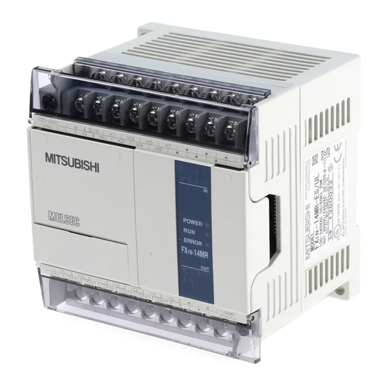
FX1S Series Programmable Controllers Installation Notes 3 Product Outline Figure 3.1: Features of the FX ➀ ➁ ➇ ➃ 100 - 240 100 - 240 ➈ POWER POWER ERROR ERROR -14MR -14MR ➅ ➉ 14MR 14MR COM0 COM1 COM2 - ES/UL... -
Page 37: Fx 1S Run/Stop Control
FX1S Series Programmable Controllers Installation Notes 3 RUN/STOP Control RUN or STOP of the FX can be controlled by: "The RUN/STOP switch mounted next to the programming port. #A standard input (X0 to X17) defined by the system parameters. $Remotely from a personal computer or other programming peripheral. -
Page 38: General Specifications
FX1S Series Programmable Controllers Installation Notes 3 General Specifications Table 3.3: General Specifications Item Description Operating Temperature 0 to 55 °C (32 to 131 °F) Storage Temperature -20 to 70 °C (-4 to 158 °F) Operating Humidity 35 to 85% Relative Humidity, No condensation... -
Page 39: Plc Mounting Arrangements
FX1S Series Programmable Controllers Installation Notes 3 PLC Mounting Arrangements To prevent a rise in temperature, mount the units to walls. Never mount them to the floor or ceiling of an enclosure. Figure 3.3: PLC Mounting Diagram > 50mm(1.97 inches) - Page 40 FX1S Series Programmable Controllers Installation Notes 3 Caution • Units should not be installed in areas subject to the following conditions: excessive or conductive dust, corrosive or flammable gas, moisture or rain, excessive heat, regular impact shocks or excessive vibration.
- Page 41 FX1S Series Programmable Controllers Installation Notes 3 • Replace the terminal cover provided, after installation or wiring work is completed, and before supplying power and operating the unit to avoid electric shock. • After reading the manual’s safety instructions, initiate the operation for making program changes while the PLC is in RUN mode, forcing ON/OFF, and switching RUN/STOP .
-
Page 42: Din Rail Mounting
FX1S Series Programmable Controllers Installation Notes 3 DIN Rail Mounting Units can be snap mounted to 35mm(1.37") DIN rail (DIN EN 50022). To release, pull the spring loaded clips away from the rail and slide the unit off and up. -
Page 43: Termination Of Screw Terminals
FX1S Series Programmable Controllers Installation Notes 3 Termination of Screw Terminals Terminal screws should be tightened to between 0.5 to 0.8 N%m. Terminal screws must be secured to prevent a loose connection thus avoiding a malfunction. The terminal screws for the FX Series PLC are M3.0. - Page 44 FX1S Series Programmable Controllers Installation Notes 3 1) Handle the crimp terminal of the following size when 1 wire is used per terminal. Refer to Figure 3.5 for installation instructions. Figure 3.4: Crimp Terminal for M3 Screws φ 3.2 (0.13") φ...
- Page 45 FX1S Series Programmable Controllers Installation Notes 3 2) Handle the crimp terminal of the following size when 2 wires are used per terminal. Refer to Figure 3.7 for installation instructions. Figure 3.6: Crimp Terminal for M3 φ 3.2 (0.13") φ 3.2 (0.13") 6.2 mm (0.24")
-
Page 46: Installing Optional Units
FX1S Series Programmable Controllers Installation Notes 3 Installing Optional Units 3.8.1 Expansion Boards The following is a generic explanation of how to install an expansion board onto the FX PLC. For greater detail and specifications of each optional unit, please see the relevant products manual. - Page 47 FX1S Series Programmable Controllers Installation Notes 3 Always make sure the power is turned off, before installing a special function board. Only one board can be used at one time, do not try to stack multiple boards. A) Special function or optional equipment board.
-
Page 48: Fx 1N -5Dm Display Module
FX1S Series Programmable Controllers Installation Notes 3 3.8.2 -5DM Display Module Always make sure the power is turned off, before installing the 5DM. A) Top cover for DM B) Optional equipment connector. C) M3 screw to secure top cover. • Remove the base unit top cover. -
Page 49: Power Supply
FX1S Series Programmable Controllers Power Supply 4 Power Supply Wiring Techniques Wiring for FX products has been designed to be safe and easy. If the user is concerned about the correct installation of these products or associated products, please contact a professional electrician who is trained to the local and national standards applicable to the installation site. -
Page 50: Power Supply
FX1S Series Programmable Controllers Power Supply 4 Power Supply • When wiring an AC supply, the “Live” cable should be connected to the “L” terminal and the “Neutral” cable should be connected to the “N” terminal. Do NOT connect the “Live”... -
Page 51: Power Supply Characteristics
FX1S Series Programmable Controllers Power Supply 4 Power Supply Characteristics Table 4.1: AC Input Power Requirements, FX -**M*-ES/UL, ESS/UL Description -10M -14M -20M -30M Power supply 100 - 240V AC, +10% -15%, 50/60 Hz Max. allowable momentary 10ms; if less than 10ms, the PLC will continue operation. -
Page 52: Power Supply Wiring
FX1S Series Programmable Controllers Power Supply 4 Power Supply Wiring Figure 4.1: AC Power Supply Example Wiring ➓ Power supply 100 - 240V AC, +10% -15%, – 50/60 Hz – 100-240 — — V AC Circuit protector or Fuse 50/60 Hz ˜... - Page 53 FX1S Series Programmable Controllers Power Supply 4 Figure 4.2: DC Power Supply Example Wiring ➓ – – Power supply 24V DC, +10% -15% — — Circuit protector or Fuse 24V DC ˜ Emergency stop š ™ Power supply switch ˜ ™...
-
Page 54: Service Power Supply
FX1S Series Programmable Controllers Power Supply 4 Service Power supply An AC powered FX can supply a service current of 24V DC at 400mA. A DC powered FX does not have the capacity to supply a service current. Earthing / Grounding Use a cable at least 0.2mm... -
Page 55: Inputs
FX1S Series Programmable Controllers Inputs 5 Inputs 24V DC Input Specifications Table 5.1: FX Input Specifications Main Unit X0 - X7 X10 - X17 Input voltage 24V DC +/- 10% Input current 24V DC, 7mA 24V DC, 5mA OFF ➔ ON >4.5mA... -
Page 56: Wiring Diagrams
FX1S Series Programmable Controllers Inputs 5 Wiring Diagrams 5.2.1 Input Wiring Figure 5.1: Input Wiring Diagrams -Source -Sink ˜ — ™ ™ – – -**M*-ES/UL, ESS/UL -**M*-ES/UL, ESS/UL ˜ š – 24V DC Service Supply — PNP Sensor ˜ NPN Sensor ™... -
Page 57: Input Circuit Connection
FX1S Series Programmable Controllers Inputs 5 5.2.2 Input Circuit Connection Figure 5.2: Input Circuit Diagrams (Source/Sink) Source (-ve S/S) Sink (+ve S/S) 24V DC 24V DC 5.2.3 Diodes and Inputs Connected in Series Figure 5.3: Diode Connection Diagram Voltage drop across the diode is Max. 4V. -
Page 58: Resistors And Inputs Connected In Parallel
FX1S Series Programmable Controllers Inputs 5 5.2.4 Resistors and Inputs Connected in Parallel Parallel resistance Rp: FX = 15kΩ. If resistance Rp is less than the stated value, then add the Rb value using the Equation 1 calculation. Alternatively; Current leakage: FX = 1.5mA. -
Page 59: Outputs
FX1S Series Programmable Controllers Outputs 6 Outputs Output Specifications Table 6.1: Output Specifications Description Relay Output Transistor Output ≤ 240V AC, ≤ 30V DC Switched voltages (resistive load) 5 - 30V DC Rated current / N points 2A/1 point, 8A/COM 0.5A/1 point, 0.8A/COM... -
Page 60: Relay Output Example
FX1S Series Programmable Controllers Outputs 6 Relay Output Example Figure 6.1: Typical Relay Wiring Diagram COM0 COM1 COM2 – š — — › ™ œ ž œ ˜ š ➓ – œ Do not use this terminal Inductive load —... -
Page 61: Reliability Tests
FX1S Series Programmable Controllers Outputs 6 6.2.1 Reliability Tests The test results in Table 6.2 were gathered from a 1 sec ON/OFF test cycle. Please note that the over current induced by in-rush greatly reduces the relay contact’s service life. The rated life for an inductive AC load such as a contactor or solenoid valve is 500,000 operations at 20VA. -
Page 62: Transistor Output Examples
FX1S Series Programmable Controllers Outputs 6 Transistor Output Examples Figure 6.2: Transistor Output Wiring Diagram – Do not use this terminal — Emergency Stop ˜ – Fuse External Mechanical ™ œ › › Interlock (See Section 6.4) ™ š... -
Page 63: Response Times
FX1S Series Programmable Controllers Outputs 6 6.3.1 Response Times OFF times increase as the load current decreases. For improved response times use a 'dummy' resistor, see Figure 6.4. If a response time of 0.5 ms or better is required when using 'light loads' use a 'dummy' resistor and ensure the signal line has a current greater than 60mA/24V DC. -
Page 64: Applying Safe Loads
FX1S Series Programmable Controllers Outputs 6 Applying Safe Loads Caution for DC Loads 1) Relay output case This PLC does not have any internal protection DC (+) DC (-) circuitry on the relay outputs. For switching direct Inductive load current on inductive loads, a reverse-current protection diode should be installed in parallel with t he l oad. - Page 65 FX1S Series Programmable Controllers Outputs 6 Caution for AC Loads 1) Relay output case This PLC does not have any internal protection 100V AC 100V AC circuitry on the relay outputs. For switching AC on Inductive load inductive loads, a surge absorber (0.1µF + “100 to 120Ω”) should be installed in parallel with the...
- Page 66 FX1S Series Programmable Controllers Outputs 6 Mechanical Interlock Ensure all loads are applied to the same side of each PLC output, see previous figures. Loads PLC output which should NEVER simultaneously operate Forward (e.g. direction control of a motor), because of a...
-
Page 67: Diagnostics
FX1S Series Programmable Controllers Diagnostics 7 Diagnostics Preliminary Checks Table 7.1: Preliminary Checks POWER Check power supply, ground and I/O cables are wired correctly. ERROR Turn the power supply on. Check that the power LED is lit. Down load a small test program to the PLC. -
Page 68: Error Led On (Cpu Error)
FX1S Series Programmable Controllers Diagnostics 7 ERROR LED ON (CPU ERROR) Table 7.2: Error LED Checks Remedy Has the memory cassette been Reset PLC. LED OFF installed or removed while the unit Fault Turn power was still powered On? POWER... -
Page 69: Common Errors
FX1S Series Programmable Controllers Diagnostics 7 Common Errors - Corroded contact points at some point in an I/O line. - An I/O device has been used outside its specified operating range. - An input signal occurs in a shorter time period than that taken by one program scan. -
Page 70: Operation And Error Flags
FX1S Series Programmable Controllers Diagnostics 7 Operation and Error Flags Table 7.3: Operation and Error Flags M8004 Error occurance M8061 PLC hardware error (ref. 8004) (ON when M8060-7 are ON) (ref. D8061) M8063 Forced RUN mode M8035 Parallel link error (ref. -
Page 71: Plc Status Registers
FX1S Series Programmable Controllers Diagnostics 7 PLC Status Registers Table 7.4: PLC Status Registers D8000 Watchdog timer (default 200msec) PLC version D8001 22100 = FX Version 1.00 22 = FX , 100 = Version 1.00 Memory capacity D8002 0002=2K steps... -
Page 72: Error Registers
FX1S Series Programmable Controllers Diagnostics 7 Error Registers Table 7.5: Error Registers D8061 Error code for PLC hardware error D8063 Error code for parallel link fault D8064 Parameter error code D8065 Syntax error code D8066 Program (circuit) error code D8067... -
Page 73: Error Codes
FX1S Series Programmable Controllers Diagnostics 7 Error Codes Table 7.6: Error Codes Check both power and D8061 Check cable connections D8063 communications connections 0000 No error 0000 No error 6301 Parity/overrun/framing error 6101 RAM error 6102 Operation circuit error 6302... -
Page 74: Instruction List
FX1S Series Programmable Controllers Diagnostics 7 Instruction List Table 7.7: Numerically Sorted PROGRAM FLOW CALL SRET IRET FEND NEXT TRANSFERS, COMP BMOV +-×÷, LOGICS WAND WXOR SHIFT SFTR SFTL SFWR SFRD DATA OPERATION 1 ZRST DECO ENCO HIGH-SPEED HSCS HSCR... - Page 75 FX1S Series Programmable Controllers Diagnostics 7 Table 7.8: Alphabetically sorted Symbol FNC No. Symbol FNC No. D P Symbol FNC No. D P ABSD DECO HOUR HSCR HSCS AND( 232-238 DRVA ASCI DRVI INCD IRET BMOV ENCO 224-230 CALL FEND...
- Page 76 FX1S Series Programmable Controllers Diagnostics 7 Symbol FNC No. Symbol FNC No. D P Symbol FNC No. D P SFWR VRRD PLSR VRSC PLSV SRET WAND PLSY PRUN TADD TCMP WXOR RAMP TSUB ZRST SEGL TZCP SFRD SFTL SFTR 7-10...
-
Page 77: Device List
FX1S Series Programmable Controllers Diagnostics 7 7.10 Device List Table 7.9: Device List Device Type Specification Remarks 2k steps by FX1S internal EEPROM Program capacity 2k steps by FX -EEPROM-8L I/O configuration Max total I/O set by Main Processing Unit... - Page 78 FX1S Series Programmable Controllers Diagnostics 7 Device Type Specification Remarks 16 points C0 to C15 General Range: 1 to 32,767 counts Type: 16 bit up counter Counters (C) Latched 16 points C16 to C31 (EEPROM Range: 1 to 32,767 counts...
- Page 79 FX1S Series Programmable Controllers Diagnostics 7 Device Type Specification Remarks D0 to D127 General 128 points Type: 16 bit data storage register pair for 32 bit device Latched D128 to D255 (EEPROM 128 points Type: 16 bit data storage register...
- Page 80 FX1S Series Programmable Controllers Diagnostics 7 Device Type Specification Remarks 16 bit: -32,768 to +32,767 Decimal K 32 bit: -2,147,483,648 to +2,147,483,647 Constants Hexadecima 16 bit: 0000 to FFFF 32 bit: 00000000 to FFFFFFFF 7-14...
- Page 81 FX1S Series Programmable Controllers INTRODUCTION TERMINAL LAYOUTS INSTALLATION NOTES POWER SUPPLY INPUTS OUTPUTS DIAGNOSTICS...
- Page 82 FX1S Series Programmable Controllers INTRODUCTION TERMINAL LAYOUTS INSTALLATION NOTES POWER SUPPLY INPUTS OUTPUTS DIAGNOSTICS...
- Page 83 Series Programmable Controllers...
- Page 84 HARDWARE MANUAL SERIES PROGRAMMABLE CONTROLLERS HEAD OFFICE: MITSUBISHI DENKI BLDG MARUNOUCHI TOKYO 100-8310 HIMEJI WORKS: 840, CHIYODA CHO, HIMEJI, JAPAN FX1S-HW-E MODEL 09R510 MODEL CODE Effective Jan. 2004 JY992D83901H Specifications are subject to change without notice. (MEE)
Need help?
Do you have a question about the FX1S series and is the answer not in the manual?
Questions and answers