Table of Contents
Advertisement
Advertisement
Table of Contents

Subscribe to Our Youtube Channel
Related Manuals for Grace Qnique 19


Summary of Contents for Grace Qnique 19
- Page 1 Copyright September 27, 2019 Grace Company (Reproduction Prohibited) Version 1.1...
-
Page 2: Important Safety Instructions
Important Safety Instructions Please read all these safety instructions before using this machine. DANGER - To reduce the risk of electric shock, do not leave the machine unattended when plugged in. Always unplug this machine from the electric outlet immediately after using and before cleaning. WARNING - To reduce the risk of burns, fire, electric shock, or injury to persons: •... - Page 3 Important Safety Instructions GROUNDING INSTRUCTIONS This product must be grounded. In the event of malfunction or breakdown, grounding provides a path of least resistance for electric current to reduce the risk of electric shock. This product is equipped with a cord that has an equipment-grounding conductor and a grounding plug. Plug the cord from the quilting machine into a surge protector.
-
Page 4: Table Of Contents
Table Of Contents Important Safety Instructions ....2 Removal Instructions ..... 62 Machine Specifications ......5 Installation Instructions ....63 Machine Layout ........6 Reinstalling the Needle Plate ....64 Ports and Plug-Ins ........8 Removal Instructions ..... 64 Included Parts & Tools ......9 Installation Instructions .... -
Page 5: Machine Specifications
Machine Specifications Product Dimensions Features Body: • Adjustable handles for efficient, extended • Height: 680.2 mm, or 26.8 inches use (page 17) • Width: 395.4 mm, or 15.6 inches • 2.4” Touch Display (page 19) • Length: 831.9 mm, or 32.8 inches •... -
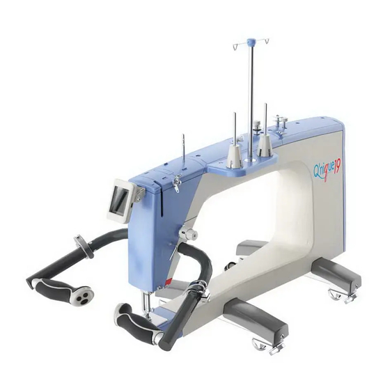
Page 6: Machine Layout
Machine Layout Quilting Machine (Side View) 1. Hand Wheel 6. Thread Mast (page 20) Raises and lowers the needle bar. Guides thread when quilting. 2. Bobbin Stand (page 29) 7. Bobbin Thread Guide (page 29) Holds the bobbin for winding. Positions thread for winding a bobbin. - Page 7 Machine Layout • Small Thread Tensioner (page 34) Lamp (page 27) Tensions thread when quilting. Lights up needle area when machine is on. • Take-Up Lever (page 34) • Needle Bar (page 56) Tensions thread when quilting. Holds the needle when quilting. •...
-
Page 8: Ports And Plug-Ins
Ports and Plug-Ins Machine Rear (Underside View) Machine Front Power On/Off Switch (page 25) Accessory Ports Turns machine on and off. For accessories. Encoder Ports (page 21) Back Handle Ports Connects encoders to machine. For back handle accessory. Quilt Motion Tablet Port Display Cable Port (page 19) For optional automation accessory. -
Page 9: Included Parts & Tools
Included Parts & Tools Please make sure all pieces are included in your kit. Front Left Wheel Front Right Wheel Back Wheel Base Front Wheel Base Cover Base Cover Assembly Base Assembly SMP-05-12166 SMP-05-12167 SMP-09-14089 SMP-09-14099 See page 16 See page 16 See page 13 See page 13 Handlebar Assembly... - Page 10 Included Parts & Tools Box 1 (Continued) Hopping Foot Screw Needle Size 18 (x11) Thumb Screw M3 SBHCS Screw (one pre-installed) (needle bar spare) M6 x 16 mm (x4) HDW-03-11736 ACC-01-11025 HDW-03-10974 HDW-03-10966 See page 56 See page 56 See page 16 See page 59 Box 2 T-handle Allen...
- Page 11 Included Parts & Tools Box 3 Lower Encoder Upper Encoder Upper Encoder Lower Encoder Spring (black) Spring (silver) (silver spring) (black spring) SMP-09-10668 SMP-09-13427 HDW-03-10216 HDW-03-10671 See page 21 See page 23 See page 69 See page 69 Box 4 Power Cord Oil Bottle SMP-02-10845...
-
Page 12: Out-Of-The-Box Assembly
Out-of-the-Box Assembly These steps are for assembling the machine when it is first removed from the packaging materials. Your quilting frame should be set up prior to machine assembly. Installing the Wheels ..................page 13 Installing the Wheel Covers ................page 16 Assembling the Handlebars ................page 17 Connecting the Display ..................page 19 Attaching the Thread Mast .................page 20... -
Page 13: Installing The Wheels
Out-of-the-Box Assembly Installing the Wheels Set up the frame before assembling the machine. Parts & Tools Needed: Back Wheel Base SBHCS Screw T-handle Allen Front Wheel Base Assembly M6 x 20 mm (x2) Wrench 4 mm Assembly Shoulder Bolt • Tape Measure (not included) M6 (x2) Instructions The machine wheels move the machine across the bottom carriage. - Page 14 Out-of-the-Box Assembly Installing the Wheels (Continued) 1. Place the front wheel base assembly Loosen two set screws on one side of the under the front of the machine with the set machine (either the right side or left side) screws facing the rear. with the 4 mm Allen wrench Front Wheel Base...
- Page 15 Out-of-the-Box Assembly Installing the Wheels (Continued) 6. Re-tighten the wheel block set screws with the 4 mm Allen wrench.
-
Page 16: Installing The Wheel Covers
Out-of-the-Box Assembly Installing the Wheel Covers Parts & Tools Needed: Front Left Wheel Front Right Wheel Back Left Wheel Back Right Wheel Base Cover Base Cover Base Cover Base Cover SBHCS Screw T-handle Allen M6 x 16 mm (x4) Wrench 4 mm Instructions 1. -
Page 17: Assembling The Handlebars
Out-of-the-Box Assembly Assembling the Handlebars Parts & Tools Needed: T-handle Allen Handlebar Assembly Wrench 4 mm Instructions Take the following steps to install and adjust the handlebars: 1. With the 4 mm T-handle Allen wrench, 1. Slide the handlebar assembly into the remove the handlebar cover screw. - Page 18 Out-of-the-Box Assembly Assembling the Handlebars (Continued) 1. Hold the handlebars at the desired angle 2. Twist the controls vertically until they are and tighten the cover screw. comfortable to hold and operate. 1. Plug the color-coded cables from the 1. Close the handlebar levers. handlebars into the machine.
-
Page 19: Connecting The Display
Out-of-the-Box Assembly Connecting the Display Parts & Tools Needed: 3. Slide the display clip into the display clip port, and plug the display cable into the display cable port. Display Cable Port 2.4 Inch Touch Display Display Clip Port Instructions Take the following steps to install the display: 1. -
Page 20: Attaching The Thread Mast
Out-of-the-Box Assembly Attaching the Thread Mast Parts & Tools Needed: Thread Stand T-handle Allen SBHCS Screw Assembly Wrench 2.5 mm M4 x 8 mm (x2) Instructions The thread stand assembly is installed onto the top of the right side of the machine. Take the following steps: 1. -
Page 21: Installing The Upper Encoder
Out-of-the-Box Assembly Installing the Upper Encoder Parts & Tools Needed: Upper Encoder T-handle Allen T-handle Allen (silver spring) Wrench 4 mm Wrench 2.5 mm Instructions The encoders monitor the position of the machine over the frame, allowing for regulated stitching. The upper encoder is installed on the outward-facing, left-rear wheel of the machine. - Page 22 Out-of-the-Box Assembly Installing the Upper Encoder (Continued) 3. Place the encoder screw into the left rear 6. Plug the encoder cable into one of the wheel hole so the encoder O-Ring is encoder ports (shown in blue) on the back between the two left machine wheels.
-
Page 23: Installing The Lower Encoder
Out-of-the-Box Assembly Installing the Lower Encoder Parts & Tools Needed: Lower Encoder Zip Tie (x2) T-handle Allen T-handle Allen (black spring) Zip Tie Mount (x2) Wrench 4 mm Wrench 2.5 mm Instructions The encoders monitor the position of the machine over the frame, allowing for regulated stitching. The lower encoder is installed on the left-rear wheel of the bottom carriage. - Page 24 Out-of-the-Box Assembly Installing the Lower Encoder (Continued) 2. Slide the wheel onto the encoder screw, 4. Turn the encoder lock collar (shown in followed by the wheel spacer. blue) to point up. Then tighten the lock collar screw with the 2.5 mm Allen wrench. Note: Depending on the encoder model, this step may require the 2.0 mm Allen wrench.
-
Page 25: Turning The Machine On/Off
Out-of-the-Box Assembly Turning the Machine On/Off Parts & Tools Needed: Power Cord Instructions The power cable port and power switch are located on the back of the machine. To power on the machine, take the following steps: 1. Lift up the power cable retainer. 3. -
Page 26: Preparing To Quilt
Preparing to Quilt Before quilting, choose the settings for your machine, load the bobbin, and thread the machine. Choosing Machine Settings ................page 27 Winding a Bobbin ....................page 29 Loading the Bobbin Case ..................page 31 Threading the Machine ..................page 34... -
Page 27: Choosing Machine Settings
Preparing to Quilt Choosing Machine Settings To customize the settings for the handlebar controls, screen buttons, or display appearance, take the following steps: Regulated 1. Press the Settings icon at the top of the touch display. Precise Regulated Settings Precise Needle Needle STOP... - Page 28 Preparing to Quilt Choosing Machine Settings (Continued) Note: While in the Settings menu, the System Information screen, or the Screen Settings menu, only two of the handlebar buttons have a function: Return to Quilting Back to Previous Menu 2. Choose desired settings: •...
-
Page 29: Winding A Bobbin
Preparing to Quilt Winding a Bobbin For information on adjusting the bobbin fill levels, see page 58. Parts & Tools Needed: Bobbin (Class M Large) Instructions Your machine comes with two bobbins pre-wound with 50 weight cotton thread. An empty M-class bobbin has also been provided. - Page 30 Preparing to Quilt Winding a Bobbin (Continued) 4. Tightly wrap the thread clockwise around 1. Run the thread through the thread mast the bobbin a few times to hold the thread guide loop directly above the thread cone. in place. Push the bobbin cam toward the bobbin to start winding.
-
Page 31: Loading The Bobbin Case
Preparing to Quilt Loading the Bobbin Case Take the following steps to insert the wound bobbin into the bobbin case and place it in the machine: 4. Pull on the bobbin case release lever to 1. Check that the needle is up. If needed, rotate the hand wheel or press and hold remove the bobbin case from the hook “Jog Needle”... - Page 32 Preparing to Quilt Loading the Bobbin Case (Continued) Note: If the bobbin is installed correctly, it turns clockwise when the thread is pulled. 7. Test the tension of the bobbin case every time bobbin thread is changed; bobbin tension is the foundation for correct thread tension.
- Page 33 Preparing to Quilt Loading the Bobbin Case (Continued) 8. Place the bobbin case inside the quilting machine with the release lever (shown in blue) at the 3 o’clock position. It should click into place. Do not pull on the lever while inserting the bobbin case.
-
Page 34: Threading The Machine
Preparing to Quilt Threading the Machine Before threading the machine, make sure you’ve selected quality thread for your project. Choosing the right thread for the machine can prevent the thread from breaking or tangling up under the needle plate. Note the following: •... - Page 35 Preparing to Quilt Threading the Machine (Continued) The following diagram outlines the path the thread (shown in blue) must take through the machine. 1. Thread Cone 5. Large Thread Tensioner Bottom Thread Guide 2. Thread Mast Guide Loop 6. Check Spring 10.
- Page 36 Preparing to Quilt Threading the Machine (Continued) 1. Rotate the hand wheel or press and hold 4. Pull the thread straight up, through the thread mast guide loop above the thread “Jog Needle” on the display to raise the needle to the top position. stand.
- Page 37 Preparing to Quilt Threading the Machine (Continued) 7. Pull the thread around the large thread 10. Pass the thread down through the bottom tensioner, between the tension discs. Wrap thread guide on the way to the needle. the thread over the check spring. Check Spring Bottom Thread...
- Page 38 Preparing to Quilt Threading the Machine (Continued) 13. Loop excess thread over the thread cutter to cut the thread. Thread Cutter...
-
Page 39: Quilting
Quilting Now that the machine is set up, it’s time to start quilting! This section of the manual describes handlebar control, using the four quilting modes, and tensioning the thread. Using the Handlebar Controls ................page 40 Using the Precise Quilting Mode ................. page 41 Using the Cruise Quilting Mode ................ -
Page 40: Using The Handlebar Controls
Quilting Using the Handlebar Controls When first turned on, the machine starts in regulated precise quilting mode and can start quilting right away. Please take a moment to review the handlebar controls used when quilting. While in the Settings menu, System Information screen, or Screen Settings menu, some buttons have a different purpose or do not function (see page 27 for details). -
Page 41: Using The Precise Quilting Mode
Quilting Using the Precise Quilting Mode The machine defaults to the precise quilting mode when turned on. In this regulated quilting mode, the machine maintains the length of the stitch despite the speed and direction of the quilter’s movements. If the quilter stops moving, the machine stops stitching. Regulated To switch to a different quilting mode, press the next quilting mode icon Precise... - Page 42 Precise Quilting Using the Precise Quilting Mode (Continued) 3. Check the stitch button icon. When stitching is inactive, pressing this button or the stitch button on the handlebars will create a single full stitch or a half-stitch, depending on the icon displayed.
-
Page 43: Using The Cruise Quilting Mode
Quilting Using the Cruise Quilting Mode In cruise mode, the quilting machine maintains the length of the stitch despite the speed and direction of the quilter’s movements. However, the machine will continue to stitch in place (at the minimum speed) if the quilter stops moving the machine. Regulated To switch to a different quilting mode, press the next quilting mode icon Precise... - Page 44 Quilting Using the Cruise Quilting Mode (Continued) 3. Check the needle stop position indicator to see if the needle will stop in the “Up” or “Down” Needle position when stitching is inactive. Pressing the icon will change the stop position. Regulated Precise •...
-
Page 45: Using The Basting Mode
Quilting Using the Basting Mode Use the basting mode to create loose, temporary stitches to hold layers of fabric together while quilting. Regulated To switch to a different quilting mode, press the next quilting mode icon Precise Baste Next Quilting Settings Mode Short... - Page 46 Precise Quilting Using the Basting Mode (Continued) 3. Check the stitch button icon. When stitching is inactive, pressing this button or the stitch button on the handlebars will create a single full stitch or a half-stitch, depending on the icon displayed.
-
Page 47: Using The Manual Quilting Mode
Quilting Using the Manual Quilting Mode In this quilting mode, the machine produces stitches at a constant speed. It’s up to the quilter to move the machine the distance needed to get the desired stitch length. This mode is useful for small, continuous stippling patterns. - Page 48 Quilting Using the Manual Quilting Mode (Continued) 3. Check the needle stop position indicator to see if the needle will stop in the “Up” or “Down” position when stitching is inactive. Pressing the icon will change the stop position. Needle Regulated •...
-
Page 49: Adjusting Thread Tension
Quilting Adjusting Thread Tension Proper thread tension prevents unwanted puckering, poorly-formed stitches, and malfunctions that can damage the fabric. Test your thread tension on extra materials before sewing on a project. Tip: Bottom thread tension is the foundation for proper thread tension. It is addressed in “Loading the Bobbin Case”... - Page 50 Quilting Adjusting Thread Tension (Continued) 2. Slowly increase the tension while stitching into scrap material similar to your project. When the thread tension is balanced, the top and bottom thread (shown in blue and red) will knot in the middle of the fabric layers. Balanced Tension Too Much Top Tension Too Little Top Tension...
-
Page 51: Tracking Stitch Count And Run Time
Settings Quilting Stitch Half Full Tracking Stitch Count and Run Time Units Stitches Stitches per cm per in To track the number of stitches your machine has sewn or hours it has run, press the System Information icon from the Settings menu (see page 27). Screen Settings System... -
Page 52: Maintaining The Machine
Maintaining the Machine Keep your machine at peak performance by practicing good machine maintenance habits. Oiling and Cleaning ..................... page 53 Changing the Needle ................... page 56 Adjusting the Bobbin Cam ................... page 58 Adjusting the Hopping Foot................. page 59 Reinstalling the Needle Plate ................ -
Page 53: Oiling And Cleaning
Maintaining the Machine Oiling and Cleaning Parts & Tools Needed: Oil Bottle Lint Brush • Compressed Air Can (optional; not included) Instructions Oil and Clean: • At the start of a new project • After 20 hours of use Machine •... - Page 54 Maintaining the Machine Oiling and Cleaning (Continued) 3. Clear debris from the spring and discs of the 6. Set the bobbin aside. Clean the bobbin case small thread tensioner. with the lint brush or compressed air. Be sure to clean the area under the bobbin tension thread arm.
- Page 55 Maintaining the Machine Oiling and Cleaning (Continued) 9. Place one to two drops of oil into the hook assembly between the inner part (shown in gray) and outer part (shown in blue). 1-2 Drops 10. Reload the bobbin case and return it to 12.
-
Page 56: Changing The Needle
Maintaining the Machine Changing the Needle For information on selecting a needle, see page 78. Parts & Tools Needed: Needle Needle Magnet Instructions A broken, bent, or burred needle may break thread, damage fabric, or even damage the machine. Always check that the needle is in good repair before starting a new project, and replace the needle after eight hours of use. - Page 57 Maintaining the Machine Changing the Needle (Continued) 7. Use the needle magnet as a visual guide. 4. Pull down on the needle to remove it from Twist the needle until the magnet points as the needle bar. straight out from the machine as possible. Note: Do not attempt to adjust the needle by moving the magnet directly.
-
Page 58: Adjusting The Bobbin Cam
Maintaining the Machine Adjusting the Bobbin Cam Parts & Tools Needed: • 1.5 mm Allen Wrench (not included) Instructions The machine’s bobbin cam is set so the bobbin will wind completely before the winder shuts off. To change how much the bobbin fills before the winding stops, take the following steps: 1. -
Page 59: Adjusting The Hopping Foot
Maintaining the Machine Adjusting the Hopping Foot Parts & Tools Needed: T-handle Allen Hopping Foot Wrench 3 mm Height Gauge Height Adjustment When quilting with thick fabric or batting layers, the hopping foot may pressing down on the quilt too tightly and begin to drag. -
Page 60: Rotation Instructions
Maintaining the Machine Adjusting the Hopping Foot (Continued) Rotation Instructions The hopping foot can be rotated to improve line of sight. To rotate the hopping foot, please take the following steps. 1. Power off the machine. 5. With the 3 mm Allen wrench, loosen the collar screw that holds the hopping foot 2. - Page 61 Maintaining the Machine Adjusting the Hopping Foot (Continued) 7. Lift the hopping foot collar back up to the presser bar, and re-tighten the collar screw. Collar Screw 8. Slide the hopping foot into the collar and screw in place with the hopping foot screw.
-
Page 62: Removal Instructions
Maintaining the Machine Adjusting the Hopping Foot (Continued) Removal Instructions To remove the hopping foot for maintenance or to adjust the hopping foot angle, take the following steps: 1. Power off the machine. 2. Rotate the hand wheel to lift the needle from the inside of the hopping foot. 3. -
Page 63: Installation Instructions
Maintaining the Machine Adjusting the Hopping Foot (Continued) Installation Instructions To install the hopping foot on your quilting machine, please take the following steps: 1. Power off the machine. 2. Slide the hopping foot to the slot in the hopping foot collar. Use the 3 mm Allen wrench and hopping foot screw to tighten in place. -
Page 64: Reinstalling The Needle Plate
Maintaining the Machine Reinstalling the Needle Plate Parts & Tools Needed: Flat-head Screwdriver Removal Instructions To remove the needle plate from the quilting machine, take the following steps: 1. Power off the machine and raise the needle to the highest position using the hand wheel. 2. -
Page 65: Installation Instructions
Maintaining the Machine Reinstalling the Needle Plate (Continued) Installation Instructions To install the needle plate onto the quilting machine, take the following steps: 1. Power off the machine. Raise the needle to 4. Place the two needle plate screws (shown the highest position using the hand wheel. -
Page 66: Calibrating The Touch Display
Settings Stitch Maintaining the Machine Half Full Calibrating the Touch Display Units Stitches Stitches per cm per in If the touch screen on the display is not working properly, the screen may need to be calibrated. Go Regulated to the Settings menu and press the Screen Settings icon Screen Precise... -
Page 67: Repairs And Diagnostics
Repairs and Diagnostics The instructions in this section should only be taken at the direction of a Grace Company support technician. If you are experiencing problems with your machine, please contact our technical support team: • Phone: (800) 264-0644 • Email: support@graceframe.com Checking the Firmware .................. -
Page 68: Checking The Firmware
Settings Repairs and Diagnostics Stitch Half Full Checking the Firmware Units Stitches Stitches per cm per in The control firmware versions for the machine motor and the touch display are found by pressing the System Information icon from the Settings menu (see page 27). Screen Settings System... -
Page 69: Replacing The Encoder Spring
Repairs and Diagnostics Replacing the Encoder Spring Please speak to a Grace Company support technician before Parts & Tools Needed: attempting these instructions. Upper Encoder Lower Encoder T-handle Allen T-handle Allen Wrench 4 mm Spring (Silver) Spring (Black) Wrench 2.5 mm Instructions If the encoder spring is over-tensioned, it may break and need to be replaced. - Page 70 Repairs and Diagnostics Replacing the Encoder Spring (Continued) 2. Slide the plastic stop, wheel spacer, washer, and broken encoder spring off the encoder. Leave the shoulder spacer on the encoder screw. Plastic Shoulder Stop Spacer Wheel Spacer Encoder Washer Spring 3.
-
Page 71: Reinstalling The Hook Holder
The hook holder keeps the hook assembly in place. The following procedure should only be attempted if determined necessary by a Grace Company support technician. If done incorrectly, major machine problems can result. Please call (800) 264-0644 before attempting this procedure. -
Page 72: Installation Instructions
Repairs and Diagnostics Reinstalling the Hook Holder (Continued) Installation Instructions 5. Turn the inside part of the hook assembly 1. Turn off the machine. (shown in blue) so that the positioning guide is at the highest point. 2. Rotate the hand wheel to raise the needle to the highest point. - Page 73 Repairs and Diagnostics Reinstalling the Hook Holder (Continued) Align the hook holder with the inside edge of the positioning guide, as shown below. Tighten the hook holder screw to fasten the hook holder in place. The inside part of the hook assembly should no longer rotate freely by hand.
-
Page 74: Timing The Machine
Improper timing can result in damage to the machine and needle, or make sewing impossible. Please consult with a Grace Company support technician by calling (800) 264-0644 before attempting to adjust the timing on your machine. - Page 75 Repairs and Diagnostics Timing the Machine (Continued) 8. Stop raising the needle once the eye is about 5. As each of the 3 set screws aligns with the level with the hook (shown in blue). Do not cut-out, loosen them with the 2 mm Allen continue to raise the needle.
- Page 76 Repairs and Diagnostics Timing the Machine (Continue) 10. Position the tip of the hook (shown in blue) in the middle of the back of the needle (shown in gray). This is easier to see from the back of the machine. 11.
-
Page 77: Appendix
Appendix This section of this manual covers additional information on quilting with your machine. Choosing Your Needle ..................page 78 Choosing Your Thread ..................page 80 Choosing Your Fabric and Batting ............... page 83 Troubleshooting Guide ..................page 84 Index ........................page 86... -
Page 78: Choosing Your Needle
Appendix Choosing Your Needle Using the wrong type of needle, or using a needle that is bent, broken, or blunt, can damage the fabric, the machine, and needle. For best results: • Use the recommended needle style for your machine (see below). •... - Page 79 Appendix Choosing Your Needle (Continued) Needle Diagram Needle Front View Needle Side View Shank Shaft Groove Scarf Point • Shank: Where the needle bar grasps the needle. • Shaft: The long, narrow part of the needle. Needle size is based upon the diameter of the needle shaft.
-
Page 80: Choosing Your Thread
Appendix Choosing Your Thread Choosing the best thread for your project is just as important as choosing the correct needle. Good thread is strong and can pass the “Yank Test” (see page 34). It holds its color well over time (colorfast), and uses long fibers (extra-long staple) that resist creating lint. - Page 81 Appendix Choosing Your Thread (Continued) Thread Size The thickness of the thread is called the weight (wt.). This number is usually stamped on the edge of the top or bottom of the thread cone. Notice that as the thread becomes heavier and thicker, the weight decreases: •...
- Page 82 Appendix Choosing Your Thread (Continued) Our Recommended Thread Finesse thread is specially-designed for quilting by the Grace Company. It can be used with domestic (sewing) and quilting machines, and comes in 60 colors. • 100% Polyester, 3-ply thread • 110/18 or 100/16 quilting machine needle •...
-
Page 83: Choosing Your Fabric And Batting
Appendix Choosing Your Fabric and Batting Fabric Some fabrics are not recommended for use with your quilting machine. Thick fabrics, such as denim or leather, have a lot of resistance that can bend or snap a needle, and misalign or break internal machinery. -
Page 84: Troubleshooting Guide
(page 25). Machine is not turned on Check power button is pressed down correctly (page 25). If problem persists, please contact a Grace Company support technician. Call (800) 264-0644. Stitches are skipped. Damaged needle Check needle (page 56). - Page 85 Needle plate is rubbing needle Check that needle plate is centered and does not hit needle (page 64). If problem persists, please contact a Grace Company support technician. Call (800) 264-0644. Machine is running loud. Machine and/or hook assembly Oil the machine and hook needs oiling assembly (page 53).
-
Page 86: Index
Appendix Index Symbols 2.5 mm T-handle Allen wrench ....... 20, 21, 23 fabric ................83 2 mm T-handle Allen wrench ........74 features ................5 4 mm T-handle Allen wrench ..13, 16, 17, 21, 23, 69 firmware ..............68 front left wheel base cover ........... - Page 87 Appendix stitches per centimeter ..........28 stitches per inch ............28 needle ................56 stitches per minute ............47 needle diagram ............79 System Information screen .......... 28 needle groove ............... 79 needle plate ..............64 needle scarf ..............79 thread ...............
- Page 88 The Grace Company 2225 South 3200 West Salt Lake City, UT 84119 Phone: 1-800-264-0644 Fax: 801-908-8888 www.graceframe.com...
Need help?
Do you have a question about the Qnique 19 and is the answer not in the manual?
Questions and answers
what does the stitch regulator do and where is it on the Qnique 19
The stitch regulator on the Grace Q'nique 19 keeps stitches consistently the same length by automatically adjusting the stitching speed based on the user's movement. As you move the machine faster or slower, the motor speeds up or slows down to match, ensuring uniform stitches. It is built into the machine and can be controlled using the handlebar buttons or screen.
This answer is automatically generated