
Related Manuals for Grace Q'nique


Summary of Contents for Grace Q'nique
- Page 1 21in Sewing Machine Copyright January 1, 2017 Jim M. Bagley, GraceWood, Inc (Reproduction Prohibited) Version 1...
-
Page 2: Table Of Contents
Table of Table of Contents Table of Contents ........................i Safety Instructions General Warnings ........................iii Grounding Instructions ......................iv Technical Data Specifications ...........................v Feature Overview ........................vi Parts & Tools .......................... vii Setup & Assembly Wheel Assembly ........................1 Handle Assembly ........................2 Handle Adjustment ........................ - Page 3 Table of Table of Contents Appendix Needle Information ........................ix Thread Information ........................x Additional Tips .........................xi...
-
Page 4: Safety Instructions General Warnings
Saftey Instructions General Warnings This appliance is not intended for use by persons (including children) with reduced physical, sensory or mental capabilities, or lack of experience and knowledge, unless they have been given supervision or instruction concerning use of the appliance by a person responsible for their safety. -
Page 5: Grounding Instructions
Saftey Instructions Grounding Instructions Grounding Methods Figure 61.1 Surge Protector To Sewing Metal Machine Screw Cover of Grounding Grounded Outlet Box Surge Adapter Protector To Sewing Machine Grounding Means Grounding GROUNDING INSTRUCTIONS This product must be grounded. In the event of malfunction or breakdown, grounding provides a path of least resistance for electric current to reduce the risk of electric shock. -
Page 6: Technical Data Specifications
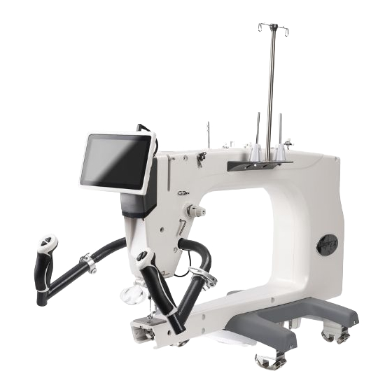
Technical Data Specifications Rear Left Front Right 1. Height: 515 mm, 20.25” 2. Width: 395 mm, 15.5” 3. Length: 824 mm, 32.4” 4. Weight: 54 lbs. 5. Quilting Arm Length: 21” W 10.5” H 6. Maximum Stitches Per Minute: 1800 7. -
Page 7: Feature Overview
Technical Data Feature Overview 1. Thread Mast Base 2. Bobbin Thread Guide 3. Bobbin Thread Tensioner 4. Bobbin Thread Cutter 5. Bobbin Wind Stand 6. Bobbin Sensor 7. Dual Thread Tension Guide 8. Small Thread Tensioner 9. Large Thread Tensioner 10. -
Page 8: Parts & Tools
Technical Data Parts & Tools Front Wheel Rear Wheel OLED Screen Handle Assembly Assembly Assembly with Cable Thread Mast Upper Encoder Plastic Base - Right Plastic Base Left Assembly (Silver Spring) Lower Encoder Short Encoder Long Encoder Bobbin Case (Black Spring) Cable Cable Bobbin (3) - Page 9 Technical Data Parts & Tools M6 x 16mm 2mm T-handle 2.5mm T-handle 3mm T-handle Shoulder Bolt (2) Allen Wrench Allen Wrench Allen Wrench 4mm T-handle 5mm T-handle Flat Head M3 Hopping Allen Wrench Allen Wrench Screw Driver Foot Screw M3 Thumb Screw Upper Encoder Lower Encoder (Needle Screw)
-
Page 10: Setup & Assembly Wheel Assembly
Setup & Assembly Wheel Assembly Parts & Tools Needed: Front Wheel Rear Wheel M6 x 16mm Assembly Assembly Shoulder Bolt (2) 4mm T-Handle M6 x 20mm (2) Allen Wrench M6 x 20mm SBHCS M6 x 16mm Shoulder Bolt Front Wheel Rear Wheel Assembly Assembly... -
Page 11: Handle Assembly
Setup & Assembly Handle Assembly Parts & Tools Needed: Handle Cover Plate Handle Assembly 4mm T-Handle M6 x 16 Allen Wrench FCHS Screw 1. Remove the Handle Cover Plate from the machine by unscrewing the four M6 x 16mm FCHS screws. Handle Assembly Handle Cable... -
Page 12: Handle Adjustment
Setup & Assembly Handle Adjustment Tools Needed: M8 Set Screw 5mm T-Handle Allen Wrench 1. Loosen the M8 set screw and lift the handles until they are at a comfortable angle, then retighten the set screw. Clamp Assembly 2. Loosen the Clamp Assembly and rotate the 3. -
Page 13: Display And Thread Mast Setup
Setup & Assembly Display & Thread Mast Setup OLED Parts & Tools Needed: Display Display Cable Connector Twist the Cable 180 Degrees OLED Display Thread Mast and Cable Assembly Display Cable Display M6 x 10mm 4mm T-Handle Clip SBHCS (2) Allen Wrench 1. -
Page 14: Carriage Adjustment
Setup & Assembly Carriage Adjustment Tools Needed: 4mm T-Handle Allen Wrench Bottom Carriage 1. Place the Sewing Machine on to the quilting frame on the bottom carriage. Wheel Support Wheel Wheel Support Support Set Screw Set Screw Wheel Support 2. Loosen the set screws on the Wheel Supports and adjust them by sliding them to the proper spacing to fit the top carriage, then retighten the set screws. -
Page 15: Plastic Base Assembly
Setup & Assembly Plastic Base Assembly Parts & Tools Needed: Plastic Base - Left Plastic Base - Right M6 x 10mm 4mm T-Handle SBHCS (4) Allen Wrench Left Plastic Base M6 x 10mm SBHCS 1. Attach the Plastic Base to the end of the Wheel Assemblies using M6 x 10mm SBHCS. 2. -
Page 16: Encoder Assembly
Setup & Assembly Encoder Assembly Parts & Tools Needed: Orientation Diagram Upper Encoder Lower Encoder (Silver Spring) (Black Spring) Rear Right 4mm T-Handle 2mm T-Handle Allen Wrench Allen Wrench The encoders must be installed Left in the left rear Front position of the top and bottom carriages... - Page 17 Section Title Setup & Assembly Subtitle Encoder Assembly Upper Encoder (Silver Spring) Lower Encoder (Black Spring) Wheel Wheel Upper Lower Encoder (Black Spring) Encoder (Silver Spring) 3. Place one of the wheels onto the Upper 4. Place the remaining wheel onto the Lower Encoder and screw it onto the left rear Encoder and screw it in to the rear left position on the Sewing Machine.
-
Page 18: Encoder Cables
Section Title Setup & Assembly Subtitle Encoder Cables Parts Needed: Long Encoder Cable Short Encoder Cable USB Connector Port Quilt Motion Control Encoder Encoder Upper Encoder (Silver Spring) Foot Pedal Short Encoder Cable 1. Plug the Short Encoder Cable into the Upper Encoder. - Page 19 Section Title Setup & Assembly Subtitle Encoder Cables Encoder Port Encoder Cables Long Encoder Lower Encoder Cable (Black Spring) 2. Plug the Long Encoder Cable into the Lower 3. Plug both encoder cables into the encoder Encoder. The tab on the cables plug should ports on the side of the sewing machine.
-
Page 20: Threading The Sewing Machine
Setup & Assembly Threading The Sewing Machine 2. Thread Mast 1. Thread Cone and Thread Stand 3. Dual Thread Tension Guide 8. Take Up Bar 4. Small Thread Tensioner 5. Thread Guide 6. Large Thread Tensioner 7. Thread Guide 9. Thread Guide 10. - Page 21 Section Title Setup & Assembly Subtitle Threading The Sewing Machine Thread Cone Thread Mast Thread Stand 1. Place thread on the cone style thread stand. 2. Pull the thread through the loop of the thread mast. Dual Thread Tension Guide Small Thread Tensioner 3.
- Page 22 Setup & Assembly Threading The Sewing Machine Large Thread Tensioner Check Spring Thread Guide 5. Feed the thread through the thread guide 6. Loop the thread down around the large thread above the large thread tensioner. tensioner and pull the thread through the tensioner disks and around the check spring.
- Page 23 Setup & Assembly Threading The Sewing Machine Thread Guide Needle Bar Eyelet 9. Pull the thread down towards the needle and 10. Feed the thread through the eyelet in the front through the bottom thread guide. of the needle bar. Eye of the Needle 11.
-
Page 24: Winding The Bobbin
Setup & Assembly Winding The Bobbin 1. Thread Mast 2. Bobbin Thread Guide 5. Bobbin Winder Cam 4. Bobbin Winder 3. Bobbin Winder Thread Tensioner Bobbin Winder The thread winds in a clock-wise direction. - Page 25 Section Title Setup & Assembly Subtitle Winding The Bobbin Thread Mast Bobbin Thread Guide 1. Pass the thread through the the thread mast. 2. Pull the thread through both holes in the bobbin thread guide. Bobbin Winder Cam Sensor Set Screw Bobbin Winder 4.
-
Page 26: Installing The Bobbin Case
Section Setup & Assembly Subtitle | Installing The Bobbin Case Bobbin Thread Slot Bobbin Thread Hole Hook Assembly Bobbin Case Latch Bobbin Thread Tension Arm 2. Place the full bobbin into the bobbin case. Pull the thread through the slot on the bobbin case. -
Page 27: Adjusting Thread Tension
Section Title Setup & Assembly Subtitle Adjusting Thread Tension Note: The thread tension will need to be adjusted anytime the thread is changed. Follow the process below to adjust the thread tension for the thread you have selected. 1. Set the bobbin case, with the bobbin inside, in When the thread your hand on its side and pull up on the thread. -
Page 28: Plugging In The Cables
Section Setup & Assembly Plugging In The Cables Power Adapter » USB Connector Port (Programming only) » Quilt Motion Control » Encoder » Encoder » Foot Pedal (For sit down system) Quilt Motion Tablet (For optional Automation Accessory ) Power Adapter Power Cord... -
Page 29: Final Checklist
Section Setup & Assembly Final Checklist Final Checklist Before you begin sewing make sure that: • The mast is attached and tightened securely. • The bobbin winder was able to fill a bobbin and stops when full. • The quilting machine is threaded correctly. •... -
Page 30: Basic Controls
Sewing Basic Controls Menu Controls Sewing Controls Increase Speed Start/ Select Scroll Up Stop Menu Back Decrease Scroll Need Up/Needle Speed Down Down Menu - This button returns the user to the main menu screen from any other screen. Back - This button will return the user to the previously viewed screen. Needle Up / Needle Down - A quick push and release of this button allows you to cycle the needle to the up or the down position. -
Page 31: Main Menu
Sewing Main Menu The Main Menu provides access to the different sewing methods and access the tools menu. Regulated Precise - In both regulated modes, the sewing machine will adjust its rate of stitching based on the speed at which the user moves the machine on the quilt frame, in order to maintain a constant stitch length. -
Page 32: Sewing Modes
Sewing Sewing Modes Over-speed Indicator - This will be green when the sewing machine is being moved within the speed limit for sewing. When the indicator turns red and beeps it means the sewing machine is being moved more quickly than the sewing machine can stitch, and will be unable to maintain the SPI setting. - Page 33 Sewing Sewing Modes Large Stitch Size Setting The baste stitch can be set to small, medium, or large. MANUAL Speed Setting Indicator The Speed indicator shows current sewing speed as a percentage of the maximum 1800 stitches per minute. The minimum being 5% and the maximum of 100%.
-
Page 34: Tools Menu
Sewing Tools Menu The tools menu allows access to information regarding the sewing machine. You can also enter the diagnostics menu to test different aspects of the machine to identify issues. HOURS 0:00 RESET RESET TOTAL TOTAL STITCH HOURS Stitch / Time This screen displays the number of stitches sewn and hours the machine has run. -
Page 35: Version
Sewing Tools Menu SYSTEM INFORMATION MAIN REV: V1.6.0 03/28/14 DISPLAY REV: V1.2.2 03/28/14 System Information This screen will display the motor control firmware version and the display control firmware version. DIAGNOSTICS ENCODER TEST BUTTON TEST SENSOR TEST SELF TESTS Diagnostics The diagnostics are used to identify where the sewing machine may be experiencing an issue. - Page 36 Sewing Tools Menu PREFERENCES DEFAULT CRUISE UNITS INCHES BASTE SMALL STITCH/INCH 10 OVER SPEED ON RIGHT HANDED Preferences This screen will be used to change defaults for various options as follows: Default: Precise/Cruise/Baste/Menu Units: Inches/Metric Inches/Baste: Small/Medium/Large Stitch/Inch: 4-16. Over Speed: On/Off Left Handed/ Right Handed: This will reverse the buttons for right or left handed users.
-
Page 37: Maintenance
Maintenance Maintenance Guide This section contains direction for cleaning and maintaining the quilting machine, and instruction to repair simple issues. For trouble shooting refer to page 40. -
Page 38: Replacing The Encoder Spring
Maintenance Replacing The Encoder Spring Parts & Tools Needed: Upper Encoder Lower Encoder 2mm T-handle 4mm T-handle Spring (Silver) Spring (Black) Allen Wrench Allen Wrench Lock Collar Long Spring Arm Washer Encoder Base Wheel Plastic Spacer Stop Encoder Short Spring Arm Spring 1. -
Page 39: Needle Plate
Maintenance Needle Plate Tools Needed: Flat Head Screwdriver Needle Needle Plate Screw Needle Plate 1. Place your needle plate on your sewing machine and rotate hand wheel to ensure needle plate orientation so that all screw holes are visible and needle enters the middle of the needle plate without contacting the needle plate at any point. -
Page 40: Hook Holder
Maintenance Hook Holder Note: Consult with technical support before attempting to adjust the hook holder. Tools Needed: 3mm T-Handle Allen Wrench 0.75mm Gap between Hook Hook Holder Holder and Hook Assembly Hook Assembly M5 X 10 FHCS 1. Rotate your hook assembly so that the positioning guide is at the highest point during 3. -
Page 41: Timing The Machine
Maintenance Timing The Machine Note: Consult with technical support before attempting to adjust the machine timing. Tools Needed: Timing Spacer 2mm T-Handle Allen Wrench Needle 0.02-0.1mm Gap Needle Hook Scarf Screws Hook Assembly 1. Remove needle plate. 2. Loosen all three hook assembly set screws with 3. - Page 42 Maintenance Timing The Machine 2mm Allen Wrench Timing Hole Timing Spacer Cut Out 4. Bring the needle so it rests on the top of timing spacer, so the groove in the needle aligns in the middle of the hook on the hook assembly. The needle should be as close as possible to the hook assembly without touching, roughly between 0.02mm and 0.075mm.
-
Page 43: Hopping Foot
Maintenance Hopping Foot Tools Needed: 3mm T-Handle Allen Wrench Hand Wheel Needle Bar 1. Using the Hand Wheel in the back of your machine, rotate your machine until the Needle Bar is in the lowest position. 3mm Allen Wrench M3 Thumb Screw 2. - Page 44 Maintenance Hopping Foot Press Bar M3 Thumb Screw Hopping Foot Needle Plate 4. Place 4 sheets of paper under the foot and lower the hopping foot to the top of the surface. You may need to use 2 sheets more or less of paper if your project is particularly thick or thin. 5.
-
Page 45: Thread Tension
Maintenance Thread Tension Proper Tension Too Much Top Tension Top Thread Fabric Thread Knot Bottom Fabric Bobbin Too Little Bobbin Tension Thread If the thread is properly tensioned the If the bobbin thread is being pulled through top thread and the bobbin thread will the top layer of fabric you need to decrease knot in the middle of the fabric layers. -
Page 46: Changing The Needle
Maintenance Changing The Needle Needle Thumb Needle *The eye of Screw Thumb the needle Screw faces the bobbin * Hand tighten Needle opening Needle Needle Thumb Screw only. *Be sure to install the needle with the scarf (indent) toward the throat of your machine. 1. - Page 47 Maintenance Cleaning & Oiling The Sewing Machine Tools Needed: Oil Bottle Separate the tension discs and clear them of lint and debris Lint Brush 1. Remove thread. 2. Remove all lint and thread remnants. • You can use canned/compressed air to clean this area.
-
Page 48: Cleaning & Oiling The Machine
Maintenance Cleaning & Oiling The Sewing Machine Clean the Clean the area inside of the under the bobbin case bobbin thread tension arm Clean the inside of the hook assembly Clean the area around the 1. Remove the bobbin. hook assembly 2. -
Page 49: Troubleshooting
Troubleshooting Troubleshooting Instruction Issue Cause Solution Troubleshooting Mechanics Hopping foot in lowest position .5mm away from needle plate Critical distances check if not working/stitching properly or Make sure Timing is correct See timing instructions making noise Check there is a proper distance between hook See hook holder instructions holder and hook assembly Machine stitching troubleshooting... - Page 50 Troubleshooting Troubleshooting Instruction Issues Cause Solution Machine stitching troubleshooting - continued Thread tension too tight Decrease tension Inspect for accidental double wrapping of thread on thread guides, make sure Machine not threaded correctly thread mast is directly over thread spool, make sure thread spool is correctly installed Move machine quicker within speed...
- Page 51 Appendix Needle Information Shank - The part of the needle that is held in the Needle Diagram needle bar. Front View Side View Shaft - The long narrow part of the needle. The Shank diameter measurement is based on the shaft. Groove - Allows the thread to pass through the fabric more easily.
- Page 52 Appendix Thread Information Things to consider when choosing a thread: • The manufacturer of the thread matters (for thread weights and quality of thread). • The weight and ply of the thread. For example: 40/3 means 40 weight 3 ply. •...
- Page 53 Appendix Additional Information Thread Thread weight is usually stamped on the edge of the spool or printed on the top or bottom of the decrease spool. Thread becomes heavier as weight designations • 60 weight, a very thin/fine thread • 50 weight •...
- Page 54 The Grace Company 2225 South 3200 West Salt Lake City, UT 84119 Phone: 1-800-264-0644 Fax: 801-908-8888 www.graceframe.com...
Need help?
Do you have a question about the Q'nique and is the answer not in the manual?
Questions and answers