Advertisement
ESP-LX Plus Site Satellite Controller Addendum
Installation, Connection and Settings
120 VAC, 60 Hz Models
ESPLX16STE
ESPLX20STE
ESPLX24STE
ESPLX16STM
ESPLX20STM
ESPLX24STM
240 VAC, 50 Hz Models
AESPLX16ST
AESPLX20ST
AESPLX24ST
AESPLX16SM
AESPLX20SM
AESPLX24SM
230 VAC, 50 Hz Models
IESPLX16ST
IESPLX20ST
IESPLX24ST
IESPLX16SM
IESPLX20SM
IESPLX24SM
Advertisement
Table of Contents

Related Manuals for Rain Bird ESP-LX Plus Series


Summary of Contents for Rain Bird ESP-LX Plus Series
- Page 1 ESP-LX Plus Site Satellite Controller Addendum Installation, Connection and Settings 120 VAC, 60 Hz Models 230 VAC, 50 Hz Models ESPLX16STE IESPLX16ST ESPLX20STE IESPLX20ST IESPLX24ST ESPLX24STE ESPLX16STM IESPLX16SM ESPLX20STM IESPLX20SM ESPLX24STM IESPLX24SM 240 VAC, 50 Hz Models AESPLX16ST AESPLX20ST AESPLX24ST AESPLX16SM AESPLX20SM AESPLX24SM...
-
Page 2: Before You Begin
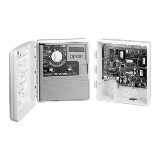
(valve wires, etc) of plus one Master Valve, simultaneously. It is an ESP-LX PLUS Controller. necessary that only one Rain Bird valve sole- noid be connected to each valve station in the NOTE: When Setting the Time and Date on controller. - Page 3 Overview of the Maxicom Interface Site Board (MISB) To convert your ESP-LX PLUS stand-alone controller into an ESP-LX PLUS SITE Satellite controller, you must install the Maxicom Interface Site Board Cabinet. Once installed, the MISB allows your ESP-LX PLUS controller to function as either an ESP-LX PLUS SITE controller in conjunction with the Maxicom 2®...
-
Page 4: Installation
INSTALLATION Select Location Follow these Guidelines to select a location for the It is recommended that you place the MISB cabinet not more than 15" (38,1 cm) horizontally from the ESP-LX Maxicom Interface Site Board (MISB) Cabinet. PLUS controller cabinet. Allow at least 9 ⁄... -
Page 5: Controller Cabinet
Minimum: ESP-LX Plus 6 3/4" MISB Cabinet (17,2 cm) Controller Cabinet Clearance Minimum 9 1/2" (24,2 cm) Maximum 15" (38,1 cm) Recommended: 6" (15,2 cm) Valve Wires MISB Data and Power Cables Primary Power Phone Cable/ Sensor Wires ESP-LX Plus Site Satellite Controller Addendum... -
Page 6: Cabinet Installation
Cabinet Installation • Disconnect the transformer from the ESP-LX PLUS ter- minal board. Mount the MISB Cabinet as described on pages 50 and 51 of the ESP-LX PLUS Installation, Programming, & • With the door and face panel removed, locate the high- Operation guide. -
Page 7: Reconnecting The Power
Installing the new transformer • If you have the standard 120-volt, 60 Hz model, use wire nuts to connect the black wire to the power source Now you are ready to install the new power transformer. hot wire, the white wire to the common wire, and the green wire to the ground wire. - Page 8 INSTALLING THE MISB DATA AND POWER CABLE In the MISB Cabinet: The ESP-LX PLUS cabinet has five knockouts for routing • The bottom (center) of the MISB Cabinet has a knock- field wires. Three are located on the underside of the cab- out for a PVC male adapter sized 1”...
- Page 9 ESP-LX Plus Site Satellite Controller Addendum...
- Page 10 Grounding Connections In the LX PLUS Controller Cabinet: • Install the ESP-LX Plus SITE front panel on the LX PLUS The MISB has built-in electrical surge protection. For the controller. Connect the ribbon cable and two-wire har- system to work, the MISB's earth ground terminal (E1) ness from the face panel to the controller’s circuit must be connected to a ground rod that is driven into the board as shown on page 48 of the ESP-LX PLUS...
- Page 11 STAND CENTRAL ALONE CONTROL REMOTE ESP-LX Plus Site Satellite Controller Addendum...
- Page 12 MAXICOM INTERFACE SITE BOARD Central Controller Connection Important: Do not set switch S2 in the center position; it must always be set fully left or right. There are two ways of connecting the ESP-LX PLUS SITE to the computer data path: the phone or serial port (RS232).
- Page 13 CCU PROM Chip Phone/ RS232 Switch DTE/DCE Switch W1 Jumper J1 Data J4 Power Connector Connector Serial Phone Sensor Connector Connector Ports Ground Terminal ESP-LX Plus Site Satellite Controller Addendum...
- Page 14 • Follow the sensor’s directions for placing and connect- controller to the sensor must be approved for ing the sensor’s probes and for setting the shutoff level, underground use. See the Rain Bird Catalog if appropriate. for exact wire specifications.
- Page 15 STAND CENTRAL ALONE CONTROL REMOTE ESP-LX Plus Site Satellite Controller Addendum...
-
Page 16: Central Control
Maxicom Communications Status Status Light When the “Central Control – Stand-Alone Switch” switch is The status light on the MISB is an indicator that the in the “Central Control” position, the LX PLUS Controller ESP-LX PLUS SITE is functioning correctly. The status display indicates the status of central control light should always be blinking at one-second intervals. - Page 17 ESP-SAT Status Light (MIB) Chip Reset Button CCU PROM Chip Phone/ RS232 Switch DTE/DCE Switch ESP-LX Plus Site Satellite Controller Addendum W1 Jumper...
- Page 18 These tabs fit into corresponding grooves in board unless advised to do so by an the cradle. Authorized Rain Bird Service technician. • To replace the PROM chip with a new chip, align the vertical tabs with the grooves in the cradle. The chip will not fit in the cradle if the chip is turned the wrong direction.
-
Page 19: Troubleshooting
Verify channel assignment on ESP-LX PLUS that are being checked to validate the failure. These val- SITE matches maximum PC channel assign- ues are meant to aid Rain Bird Engineers during technical ments. troubleshooting. For the ESP-LX+SITE, if you encounter a “SCR X”... - Page 20 Phone: (626) 963-9311 Phone: (520) 741-6100 Fax: (626) 963-4287 Fax: (626) 812-3411 Fax: (520) 741-6522 Rain Bird Technical Service (800) 247-3782 (U.S. and Canada only) www.rainbird.com CentralControl@rainbird.com ® Registered trademark of Rain Bird Corporation P/N 636051-1 © 2003 Rain Bird Corporation 12/03...
Need help?
Do you have a question about the ESP-LX Plus Series and is the answer not in the manual?
Questions and answers