Table of Contents
Advertisement
Quick Links
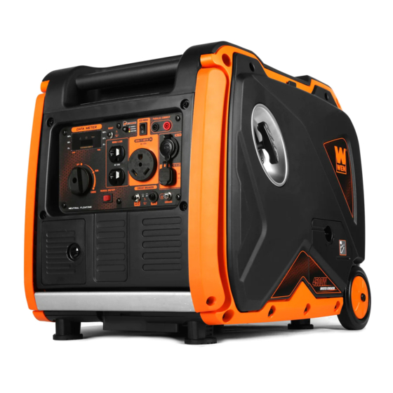
MODEL 56450iX
4500-WATT
INVERTER GENERATOR
Instruction Manual
NEED HELP? CONTACT US!
Have product questions? Need technical support? Please feel free to contact us:
1-800-232-1195 (M-F 8AM-5PM CST)
TECHSUPPORT@WENPRODUCTS.COM
IMPORTANT: Your new tool has been engineered and manufactured to WEN's highest standards for dependability,
ease of operation, and operator safety. When properly cared for, this product will supply you years of rugged,
trouble-free performance. Pay close attention to the rules for safe operation, warnings, and cautions. If you use
your tool properly and for its intended purpose, you will enjoy years of safe, reliable service.
WENPRODUCTS.COM
For replacement parts and the most up-to-date instruction manuals, visit
Advertisement
Table of Contents

Related Manuals for Wen 56450iX


Summary of Contents for Wen 56450iX
- Page 1 1-800-232-1195 (M-F 8AM-5PM CST) TECHSUPPORT@WENPRODUCTS.COM IMPORTANT: Your new tool has been engineered and manufactured to WEN’s highest standards for dependability, ease of operation, and operator safety. When properly cared for, this product will supply you years of rugged, trouble-free performance. Pay close attention to the rules for safe operation, warnings, and cautions. If you use your tool properly and for its intended purpose, you will enjoy years of safe, reliable service.
-
Page 2: Table Of Contents
Exploded View & Parts List ................37 Warranty Statement ..................48 WENPRODUCTS.COM To purchase accessories for your tool, visit Magnetic Oil Dipstick (Model No. 55201) Weatherproof Generator Cover (Model No. 56310iC) WEN Parallel Connection Kit High-Altitude Kit (Part No. 56450i-HA36 & 56450i-HA68) -
Page 3: Welcome
SPECIFICATIONS GENERATOR Surge Wattage 4500 Watts Rated Wattage 3500 Watts AC: 120V Rated Voltage DC: 12V (Cigarette Lighter), 5V (USB) Rated Amperage 29.16A Phase Single Frequency 60 Hz Decibel Rating 58 dB Length: 23.2 in. (590 mm) Product Dimensions Width: 18 in. (456 mm) Height: 20.1 in. -
Page 4: Introduction
INTRODUCTION Thanks for purchasing the WEN 4500-Watt Inverter Generator. Refer to the illustration below for the location of the serial number on the side of the engine and on the main specifications label. Record the generator information in the spaces provided below. If assistance for information or service is required, please contact customer service by call- ing 1-800-232-1195, M-F 8-5 CST;... -
Page 5: Safety
WEN reserves the right to change this product and specifications at any time without prior notice. At WEN, we are continuously improving our products. If you find that your tool does not exactly match this manual, please visit wenproducts.com for the most up-to-date manual or contact customer service at 1-800-232-1195, M-F 8-5 CST. -
Page 6: Generator Safety Warnings
GENERATOR SAFETY WARNINGS DANGER! CARBON MONOXIDE Using a generator indoors CAN KILL YOU IN MINUTES. Generator exhaust contains carbon monoxide (CO). This is a poison gas you cannot see or smell. If you can smell the generator exhaust, you are breathing CO. But even if you cannot smell the exhaust, you could be breathing CO. - Page 7 GENERATOR SAFETY WARNINGS WARNING! Do not let comfort or familiarity with the product replace strict adherence to product safety rules. Failure to follow the safety instructions may result in serious personal injury. OPERATING ENVIRONMENT 3. If any part of the generator, electrical device or pow- er cord is broken, damaged, or defective, make sure 1.
- Page 8 GENERATOR SAFETY WARNINGS WARNING! Do not let comfort or familiarity with the product replace strict adherence to product safety rules. Failure to follow the safety instructions may result in serious personal injury. TO MAXIMIZE THE LIFESPAN OF YOUR GENERATOR: We recommend running your generator at least once a month for 20 to 30 minutes.
-
Page 9: Before Operating
UNPACKING & PACKING LIST UNPACKING With the help of a friend or trustworthy foe, such as one of your in-laws, carefully remove the generator from the packaging and place it on a sturdy, flat surface. Make sure to take out all contents and accessories. Do not discard the packaging until everything is removed. -
Page 10: Know Your Inverter Generator
KNOW YOUR INVERTER GENERATOR TOOL PURPOSE Inverter Generators provide you with clean and quiet power, when and where you need it most. Refer to the fol- lowing diagrams to become familiarized with all the parts and controls of your Generator. The components will be referred to later in the manual for assembly and operation instructions. - Page 11 Push down for 10 sec. to shutoff generator manually. 5. Parallel Connection Port 14. 3-in-1 Switch Connect two WEN inverter generators through a parallel Turn switch to choke, run, and automatically shut off the connection kit for a higher output.
-
Page 12: Generator Preparation
GENERATOR PREPARATION REMOVING THE MOUNTING PLATES Your generator is shipped with four mounting plates that secure the engine to the generator housing in order to prevent machine damage during shipping. Make sure to remove the four mounting plates before operating your generator. - Page 13 GENERATOR PREPARATION The following section describes the necessary steps to prepare the generator for use. If you are unsure about how to perform any of the steps, please call (800) 232-1195 M-F 8-5 CST for customer service. Failure to perform these steps properly can damage the generator or shorten its life.
- Page 14 The oil level of the engine should be checked before each Upper Limit start to ensure that the engine crankcase contains suf- ficient lubricant. TIP: Your WEN generator is compatible with the WEN 55201 Magnetic Oil Dipstick (not included), available Lower Limit for purchase at wenproducts.com. The dipstick’s in- dustrial-strength magnetic tip will collect metal shav- ings from your generator’s oil compartment to help...
- Page 15 GENERATOR PREPARATION STEP 2 - ADD / CHECK FUEL WARNING! RISK OF EXPLOSION. HIGHLY FLAMMABLE: This generator may emit highly flammable and explosive gasoline vapors, which can cause severe burns or even death, if ignited. A nearby open flame can lead to explosion even if not directly in contact with gasoline.
- Page 16 GENERATOR PREPARATION STEP 5 - GROUND THE GENERATOR Fig. 7 To reduce the risk of electric shock and to maximize safety, the genera- tor should be properly grounded. Ground the generator by tightening the grounding nut (Fig. 7) on the front control panel against a grounding wire.
-
Page 17: Operation & Maintenance
STARTING YOUR GENERATOR Before starting the generator, make sure you have read and performed the steps in the “Generator Preparation” section of this manual. If you are unsure about how to perform any of the steps in this manual please call 1-(800) 232-1195 M-F 8-5 CST for customer service. - Page 18 STARTING YOUR GENERATOR BEFORE STARTING THE GENERATOR 1. Verify that generator is outside on a dry, level surface with at least two feet of clearance on all sides. 2. To maximize safety, check that the generator is properly grounded (see “Ground the Generator”). 3.
-
Page 19: Using Your Generator
USING YOUR GENERATOR CALCULATING THE WATTAGE OF YOUR DEVICE(S) Connect electrical devices running on AC current according to their wattage requirements. Calculate the total run- ning wattage and starting wattage of the device(s) you wish to connect, and MAKE SURE that they are within the capacity of your generator and the capacity of each individual outlet. - Page 20 USING YOUR GENERATOR CALCULATING THE WATTAGE OF YOUR DEVICE(S) - CONTINUED The chart below serves as a reference for the estimated wattage requirements of common electrical devices. How- ever, do not solely rely on this chart - all electronics and appliances are built differently. Always check the wattage listed on the electrical device before consulting this chart.
- Page 21 USING YOUR GENERATOR CONNECTING ELECTRICAL DEVICES When the rated wattage requirement of each electrical device has been determined, add these numbers to find the total rated wattage needed. If this number exceeds the rated wattage (3500W) of the generator, DO NOT connect all these devices.
- Page 22 USING YOUR GENERATOR SOME NOTES ABOUT POWER CORDS Long or thin cords can drain the power provided to an electrical device by the generator. When using such cords, allow for a slightly higher rated wattage requirement by the electrical device. Device Requirements Max.
- Page 23 PARALLEL OPERATION Fig. 12 The parallel connection ports (Fig. 12) allow you to connect two WEN generators to increase the total available electrical power. The WEN Parallel Connection Kit can be purchased from wenproducts.com. Follow the instructions included with your parallel connection kit for proper installation and operation.
- Page 24 • The CO sensor has a lifetime of about 7 years, and is capable of monitoring its lifetime. If your generator shows an error light several years after purchase, it may be time to replace the CO sensor. Contact WEN customer service...
- Page 25 USING YOUR GENERATOR MULTI-METER The multi-meter on your generator switches between voltage (e.g. 120.1), frequency (e.g. 60.0H), and runtime (e.g. 12.3) every 5 seconds. When you first use the generator, the meter will count runtime, but will not store runtime until the generator is run for longer than 2 hours at a time.
-
Page 26: Stopping Your Generator
OPTION 1: AUTOMATIC FUEL SHUTOFF (RECOMMENDED) The WEN 4500W Inverter Generator is equipped with automatic fuel shutoff. This feature turns off the flow of fuel, allowing for the generator to use up the remaining fuel from the carburetor before turning off. This prolongs the lifespan of the generator by preventing build-up and blockages caused by stagnant fuel inside of a carburetor. -
Page 27: Maintenance
MAINTENANCE Proper routine maintenance of the generator will help prolong the life of the machine. Please perform maintenance checks and operations according to the schedule in Table 4. CAUTION! Never perform maintenance operations while the generator is running. Before maintaining or servicing the generator, turn OFF the generator, disconnect all devices and allow the generator to cool down. - Page 28 5. Reinstall dipstick and wipe clean any spilled oil with a rag. Reinstall the oil access cover. TIP: Your WEN generator is compatible with the WEN 55201 Magnetic Oil Dipstick (not included), available for purchase at wenproducts.com. The dipstick’s industrial-strength magnetic tip will collect metal shavings from...
- Page 29 MAINTENANCE DRAINING THE CARBURETOR We recommend draining the carburetor after every use and before storing the generator. (If the generator is shut off using the AUTO OFF/FUEL OFF, it is only necessary to drain it before periods of long storage.) Draining the car- buretor can prevent the fuel from clogging up the carburetor;...
- Page 30 MAINTENANCE AIR FILTER MAINTENANCE Check every 50 hours of operation (refer to Table 4 - Recommended Maintenance Schedule). Routine maintenance of the air filter helps maintain proper airflow to the carburetor. Occasionally check that the air cleaner is free of excessive dirt. To inspect and clean the air filter: Fig.
- Page 31 MAINTENANCE SPARK PLUG MAINTENANCE Refer to Recommended Maintenance Schedule in Table 4 for maintaining the spark plug. The spark plug is important for proper engine operation. Check the spark plug regularly to maintain proper engine operation. A good spark plug should be intact, free of deposits, and properly gapped. To inspect or replace the spark plug: Fig.
- Page 32 MAINTENANCE DRAINING / CHANGING OIL Change the oil according to the Recommended Maintenance Schedule in Table 4. Change the oil MORE OFTEN if operating under heavy load or high ambient temperatures. It is also necessary to drain the oil from the crankcase if it has become contaminated with water or dirt. Changing the oil when the engine is warm allows for more-complete drainage.
- Page 33 MAINTENANCE DRAINING THE FUEL TANK Drain and clean the fuel tank each year, or before storing the generator for longer than two months. To drain the fuel tank and carburetor: Fig. 26 1. Using a Phillips-head screwdriver, remove the service panel on the opposite side of the recoil starter by unscrewing the top two screws (Fig.
-
Page 34: Transportation & Storage
TRANSPORTATION & STORAGE TRANSPORTING THE GENERATOR To prevent fuel spillage when transporting, be sure to perform the following: 1. Tighten the fuel cap. 2. Flip the engine switch to the OFF position. 3. Drain the fuel tank if possible. Refer to section, “Draining the Fuel Tank.” 4. -
Page 35: Troubleshooting Guide
TROUBLESHOOTING GUIDE WARNING! Stop using the generator immediately if any of the following problems occur or risk serious personal injury. If you have any questions, please contact customer service at 1-800-232-1195 (M-F 8-5 CST), or email techsupport@wenproducts.com. PROBLEM POSSIBLE CAUSE SOLUTION 3-in-1 switch is set to OFF. -
Page 36: Wire Diagram
WIRE DIAGRAM... -
Page 37: Exploded View & Parts List
EXPLODED VIEW & PARTS LIST Fig. 1 - Crankcase Assembly Fig. 2 - Crankcase Cover Assembly Part No. Description Qty. Part No. Description Qty. Crankcase Subas- 56380i-0201 Cover, Crankcase 56380i-0101 sembly 56200-0803 56380i-0102 Flat Washer, 10mm Deep-Groove Ball 56380i-0203 Connector, Oil Drain Bearing, 6205 56380i-0103 Hose... - Page 38 EXPLODED VIEW & PARTS LIST Fig. 3 - Cylinder Head Assembly Part No. Description Qty. Part No. Description Qty. 56200-1202 Bolt, M6x20 Cylinder Head Subas- 56450i-0307 sembly Cylinder Head Cover 56380i-0302 Subassembly 56310i-0109 Bolt, M8x34 Cylinder Head Cover 56380i-0303 56380i-0309 Stud Bolt, M6x105 Gasket 3-10...
- Page 39 EXPLODED VIEW & PARTS LIST Fig. 5 - Piston Ring Set & Connecting Rod Part No. Description Qty. 56310i-0501 Piston Ring Assembly Fig. 6 - Valve Train & Camshaft Subassembly 56310i-0505 Piston Pin Clip Part No. Description Qty. 56380i-0503 Piston 56380i-0601 Camshaft Assembly 56310i-0504...
- Page 40 EXPLODED VIEW & PARTS LIST Fig. 8 - Carburetor Assembly Fig. 9 - Impeller, Alternator Part No. Description Qty. Part No. Description Qty. Carburetor 56380i-0801 Flywheel Nut, M14- Insulator Gasket 56310i-1101 Carburetor 56380i-0802 56380i-0902 Impeller Insulator Plate Socket Head Cap 56310i-1103 56380i-0803 Carburetor Gasket...
- Page 41 EXPLODED VIEW & PARTS LIST Fig. 11 - Muffler Assembly Part No. Description Qty. 11-1 56380i-1101 Shroud 11-2 56380i-1102B Muffler Cover Support 11-3 56380i-1103 Impeller 11-5 56380i-1105 Muffler Assembly 11-6 56380i-1106 Muffler Gasket 11-7 56310i-1010 Nut, M8 11-8 56380i-1108 Muffler Bracket 11-9 56310i-1009 Bolt, M8x16...
- Page 42 EXPLODED VIEW & PARTS LIST Fig. 12 - Fuel Tank Assembly Part No. Description Qty. 12-1 56380i-1201 Fuel Tank Assembly 12-2 56380i-1202 Fuel Gauge 12-3 56380i-1203 Fuel Tank Outlet 12-4 56200-1202 Bolt, M6x20 12-5 56380i-1205 Flat Washer, 6mm 12-6 56380i-1206 Bushing 12-7 56380i-1207...
- Page 43 EXPLODED VIEW & PARTS LIST Fig. 13 - Frame Part No. Description Qty. Part No. Description Qty. Engine Frame As- 13-7 56380i-1317B Air Filter Hose 13-1 56380i-1301 sembly Secondary Carbon 13-18 56380i-1318 Socket Button Tank Hose 13-2 56450i-1302 Head Screw, 13-19 56380i-1319 Clamp...
- Page 44 Grounding Nut 14-10 56380i-1410 Panel Seat 14-28 56380i-1428 NEMA TT-30R Outlet 14-11 56200-0302 Screw, M5x12 14-29 56380i-1429 DC Breaker, 10A 56450iX- Control Panel Subas- 14-12 14-30 56380i-1430 AC Breaker, 20A 1412ASM sembly 14-31 56380i-1431 Shutdown Switch 14-13 56200-0514 Screw, M4x16...
- Page 45 EXPLODED VIEW & PARTS LIST Fig. 15 - Handle Part No. Description Qty. Part No. Description Qty. 15-1 56380i-1501 Handle Tube 15-9 56380i-1509 Bolt, M6x10 15-2 56380i-1502 Left Rotation Arm 15-10 56310i-0209 Bolt, M6x16 15-3 56380i-1503 Right Rotation Arm 15-11 56310i-1807 Nylon Nut, M6 Left Handle...
- Page 46 EXPLODED VIEW & PARTS LIST Fig. 16 - Side Covers Part No. Description Qty. Part No. Description Qty. 16-1 56380i-1601 Left Cover Recoil Starter Guide 16-10 56380i-1610 Subassebly 16-2 56200-0406 Bolt, M5x12 16-3 56380i-1603 Left Shell 16-11 56200-0302 Screw, M5x12 16-4 56380i-1604 Right Shell...
- Page 47 EXPLODED VIEW & PARTS LIST Fig. 17 - Baseplate Part No. Description Qty. 17-1 56380i-1701 Baseplate Engine Frame Damper 17-2 56380i-1702 Seat 17-3 56310i-1201 Bolt, M6x16 17-4 56200-0408 Nut, M6 17-5 56380i-1705 Reinforcement Plate 17-6 56380i-0313 Bolt, M6x12 17-7 56310i-1407 Cover Plug 17-8 56380i-1619...
-
Page 48: Warranty Statement
(3) years from date of purchase or 500 hours of use; whichever comes first. Ninety days for all WEN products if the tool is used for profes- sional or commercial use.
Need help?
Do you have a question about the 56450iX and is the answer not in the manual?
Questions and answers