Advertisement
CALIBRATION INSTRUCTIONS (Ver. 5, 6, 7 Software)
Note: Below, position Weight A kg refers to the switch position furthest away
from the test/data socket. Weight A lb refers to the switch position next to
Weight A kg.
1. NO calibration Jack is required for this version 5,6 and 7 UC321.
2. Set the mode switch on the bottom of the UC321 to the position furthest
away from the test/data socket.
3. Press the Blue Measure Switch once then slide the mode switch towards
the test/data socket, (all the way) and then back again. Within two seconds.
4. If the display shows "- - - - - ", press Measure Switch three times.
5. After the display turns off then back on the display will show "- - - - - " again.
6. Press Measure Switch momentarily. The display will show "99999
to count down. Press Measure Switch. The display will show "0 0 0 0 "
7. To check the calibration type set the mode switch to the position furthest
away from the test/data socket and press the measure switch.
By default, scale is set to l l l l - - - - 1 1 1 1 , which uses 3 point calibration.
To change set mode switch to the next position towards the test/data socket
then press Measure Switch momentarily. Use Measure Switch to change
setting.
l l l l - - - - 0 0 0 0 :2 point, (0kg,150kg).
l l l l - - - - 1 1 1 1 :3 point, (0kg,80kg,150kg). * DEFAULT.
l l l l - - - - 2 2 2 2 :2 point, (0lb,350lb).
l l l l - - - - 3 3 3 3 :3 point, (0lb,176.4lb(80kg),350lb).
Slide Mode switch to position furthest away from the test/data socket press
Measure Switch repeatedly to show "
8. Press Measure Switch momentarily, the display will show the temperature
at calibration; i.e. (20
9. To change set mode switch to Weight A lb position then press Measure
Switch, press Measure Switch momentarily, the temperature value will
increase one digit at a time. When the correct temperature is displayed slide
Mode switch to Weight A kg press Measure Switch display "6 6 6 6 "
10. Press Measure Switch momentarily, the display will show the gravity
setting applied at time of calibration, i.e. (9798
11. To change set mode switch to Weight A lb position then press Measure
Switch,
12. Press Measure Switch momentarily to increment the value one digit at a
time. Once the correct value is displayed, slide Mode switch to Weight A kg
press Measure Switch press Measure Switch to display "7 7 7 7 "
13. Press Measure Switch momentarily, the display will show the gravity
setting for the location of use of the scale, i.e. (9798
used at the same location, where it is calibrated, this value must be set
exactly the same as above!
14. Use the same procedure as above to set the gravity value.
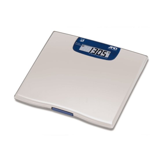
UC-321PL UC321-BT UC-321
20). This must be set before calibration.
20
20
........cont. page 2
5 5 5 5
"
9798).
9798
9798
9798). If the scale is to be
9798
9798
Page 1 of 2
99999
99999" and start
99999
Page 1 of 2
Advertisement
Table of Contents

Subscribe to Our Youtube Channel
Related Manuals for A&D UC-321PL


Summary of Contents for A&D UC-321PL
- Page 1 Page 1 of 2 UC-321PL UC321-BT UC-321 CALIBRATION INSTRUCTIONS (Ver. 5, 6, 7 Software) Note: Below, position Weight A kg refers to the switch position furthest away from the test/data socket. Weight A lb refers to the switch position next to Weight A kg.
- Page 2 Page 2 of 2 UC-321 BT CALIBRATION INSTRUCTIONS .cont. (Ver. 5, 6, 7 Software) 10”. 15. Press Measure Switch to display “10 16. Press Measure Switch momentarily, the display will show C C C C l l l l 0 0 0 0, remove all weight from the platform and position the timber calibration jig.
Need help?
Do you have a question about the UC-321PL and is the answer not in the manual?
Questions and answers
What does P1, P2, P3-P8 mean