Table of Contents
Advertisement
Balanced Flue Gas Stoves
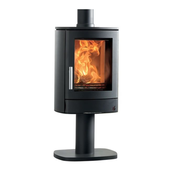
NEO
USER, INSTALLATION & SERVICING INSTRUCTIONS
For use in GB & IE (United Kingdom and Ireland)
This appliance has been tested and cer�fied for other coun�es (see technical data). However to install appliance in other countries, modifica�on
of the appliance and its method of installa�on may be necessary in order to use the appliance safely and correctly. The manual for the local
language must be obtained. Contact ACR for further informa�on.
To be retained by the user for future reference.
Advertisement
Table of Contents

Related Manuals for ACR STOVES NEO


Summary of Contents for ACR STOVES NEO
- Page 1 Balanced Flue Gas Stoves USER, INSTALLATION & SERVICING INSTRUCTIONS For use in GB & IE (United Kingdom and Ireland) This appliance has been tested and cer�fied for other coun�es (see technical data). However to install appliance in other countries, modifica�on of the appliance and its method of installa�on may be necessary in order to use the appliance safely and correctly.
-
Page 2: Table Of Contents
Contents Thankyou for purchasing an ACR Gas Stove. To ensure you gain the most from your purchase, please read through this manual before opera�ng for the first �me. Please keep this manual safe as it will be required to be completed by your Gas Safe engineer a�er each annual service. - Page 3 NEO3FGAS – Neo 3F Gas Stove, 2 side windows 1 front door glass on 4 legs NEO3PGAS – Neo 3P Gas Stove , 2 side windows 1 front door glass on a pedestal. This ACR gas appliance is a high efficiency, Balanced Flue Live Fuel Effect appliance. It provides radiant and convected heat using the latest burner technology.
-
Page 4: User Instruc�Ons
User Instruc�ons Before installa�on, check that the local distribu�on condi�ons, nature of the gas and pressure, and adjustment of the appliance are compa�ble. This appliance is intended for use on a gas installa�on with a governed meter. This gas installa�on may only be installed by a registered professional competent person (Gas Safe installer in the UK). -
Page 5: Symax Handset User Instruc�Ons
Symax Handset User Instruc�ons Technical Data NOTICE AMBIENT TEMPERATURE RANGE To keep the Receiver free from debris, dirt, and humidity, do not CSA: 32 °F to 131 °F remove the Receiver from the plas�c bag un�l all construc�on is CE: 0 °C to 55 °C complete. - Page 6 Symax Handset User Instruc�ons Deac�vate Func�ons Install ba�eries. All icons are displayed and flashing. While the icons are flashing, press the relevant func�on bu�on and hold for 10 sec. The func�on icon will flash un�l deac�va�on is complete. Deac�va�on is complete when the func�on icon and two horizontal bars are displayed.
- Page 7 Symax Handset User Instruc�ons 10 Bu�on Handset Layout Se�ng The Fahrenheit or Celsuis Se�ng The Time To change between °C and °F, press bu�ons simultaneously. NOTE: Choosing °F results in a 12 hour clock. Choosing °C results in a 24 hour clock. Child Proof Press bu�ons simultaneously.
- Page 8 Symax Handset User Instruc�ons NOTICE BEFORE OPERATING Make sure MANUAL knob on the GV60 valve is in the ON, full counter clockwise posi�on. Place the ON / OFF switch (if equipped) in the I (ON) posi�on. When pilot igni�on is confirmed, motor turns automa�cally to maximum flame height. If the pilot does not stay lit a�er several tries, turn the main valve knob to OFF To Turn ON Fire Countdown Timer...
- Page 9 Symax Handset User Instruc�ons Modes of Opera�on Eco Mode Thermosta�c Mode ON: Press bu�on un�l temperature gage is displayed, present temperature is Press bu�on to enter Eco Mode. displayed briefly, and then room displayed. temperature is displayed. OFF: OFF: Press bu�on.
- Page 10 Symax Handset User Instruc�ons Program Mode - con�nued Default Se�ng ON TIME (Thermosta�c) TEMPERATURE: 70 °F / 21 °C OFF TIME TEMPERATURE: “- -” (pilot flame only) Press bu�on and hold un�l flashes and set temperature (se�ng in Thermosta�c Mode) is displayed.
- Page 11 Symax Handset User Instruc�ons NOTE: Either con�nue to PROGRAM 2 and set ON and OFF �mes or stop programming at this point, and PROGRAM 2 remains deac�vated. NOTE: PROGRAM 1 and 2 use the same ON (Thermosta�c) and OFF temperatures for ALL, SA:SU and Daily �mer (1,2,3,4,5,6,7) Once a new ON (Thermosta�c) and / or OFF temperature has been set, that temperature becomes the new default se�ng.
-
Page 12: Manual User Instruc�Ons
Manual User Instruc�ons Knob Se�ngs KNOB POSITION FUNCTION Main valve Permits main gas flow through valve. knob Permits main gas flow through valve if pilot is lit and Main valve thermocouple is generating sufficient power. knob Allows pilot to the manually ignited and prevents main gas Manual knob flow. -
Page 13: Cleaning & Maintenance
Cleaning & Maintenance Never a�empt any cleaning or maintenance of the appliance unless the appliance is cold This appliance should be inspected and serviced once a year by a qualified, competent and registered person. The inspec�on and maintenance must at least ensure that the appliance is working correctly and safely. - Page 14 Installa�on Instruc�ons Protec�ve clothing should be worn when installing the appliance. Care should be taken when li�ing this appliance due to it’s weight. We strongly recommend a carbon monoxide detector (conforming to EN50291) is permanently fixed in the same room as the appliance. Ensure that the Flue Terminal is not in any way obstructed and is clear of vegeta�on, i.e.
-
Page 15: Installa�On Instruc�Ons
Installa�on Instruc�ons Gas Connec�on This appliance has a gas inlet connec�on of Ø 8mm. Ven�la�on This appliance is a Balanced Flue room sealed appliance, and as such needs no addi�onal ven�la�on. However, an adequate supply of fresh air to maintain temperatures and a comfortable environment is recommended. -
Page 16: Clearance Requirements
Clearance Requirements Corner Installa�on – Distance to combus�bles Side & Rear – Distance to combus�bles 100mm 75mm 100mm 500mm Above – Distance to combus�bles 250mm All clearances stated provide the minimum distance to combustible material. If the appliance is to be installed in a non-combustible opening, these clearances can be reduced but the clearance for the rear must always be 50mm minimum. -
Page 17: Installa�On Of Appliance
Installa�on of the appliance The appliance is supplied in separate boxes, please refer to the packing list above. The installer is required to install the burner, op�onal rear panel, op�onal LED kit and log set to the appliance. Flue configura�on The appliance is pre-set with a ver�cal flue configura�on, if this is the desired flue route then no further ac�on needs to be taken. -
Page 18: Burner Installa�On
Burner installa�on Before connec�ng the burner please ensure that the gas supply pipework is in the correct posi�on for connec�on to the unit, please ensure that the gas supply pipework is purged and free from debris. 1. To access the combus�on chamber please loosen the retaining bolt located in the handle below the roller cam locking mechanism. - Page 19 4. Place the control box into the holder located on the underside back le� of the appliance ensuring that the wiring is not trapped in any way. 5.Replace the perforated grate. 6. Place the elevated burner ports onto the le� and right gas outlets as shown. The le�- hand elevated port should sit in the 6 groove from the front.
-
Page 20: Flue Connec�On
Flue Connec�on General Notes This appliance may be installed with a roof terminal or a wall terminal. This appliance may only be used with Balanced Flue (otherwise known as Concentric Flue) parts as specified by ACR. The ACR specified flue parts have been approved with the appliance. - Page 21 Terminal Guards The flue outlet should be protected with a terminal guard conforming to BS5440-1 if persons could come into contact with it, or if it could be damaged or if it is in a vulnerable posi�on such as where the flue discharge is within easy reach from the ground (less than 2m) balcony, veranda or an opening window.
- Page 22 Maximum pipe extension, for outside wall (H) Part No. USDVC 100 = 1 X Ver�cal Pipe Rise (V). For Ø100/150 flue. Minimum Ver�cal Flue Height: Neo - 0.5m Maximum Permissible Run (H) =15m. Flue Restrictors to be fi�ed, Ø100/150: Flue Restrictors to be fi�ed, Ø100/150:...
- Page 23 Rear Flue Configura�on IMPORTANT Kit 2 Components: When using the rear flue op�on from the Wychwood Gas Stove, it is impera�ve that the below configura�on is adhered to at all �mes. Snorkel The Snorkel Terminal (GFK2 ACR REAR SNORKEL KIT) MUST always be installed inline with manufacturers instruc�ons and a maximum horizontal length of 500mm before affixing...
- Page 24 Examples of possible alterna�ve flueing arrangements* *Contact your local dealer for more informa�on...
- Page 25 Examples of possible alterna�ve flueing arrangements* *Contact your local dealer for more informa�on...
- Page 26 Examples of possible alterna�ve flueing arrangements* *Contact your local dealer for more informa�on...
- Page 27 Examples of possible alterna�ve flueing arrangements** **Contact your local dealer for more informa�on...
- Page 28 Log Layout This kit will contain: Crystals *Crystals are only available with LED light options Bark Effect Fireglow Fibres 8 Realistic Hard Ceramic Logs 2 Elevated Burner Ports...
- Page 29 Log Layout Step 1 - Place the elevated burner ports into the lower burner ports. Press firmly down to secure. This is where the gas will be released from & enter into the stove chamber. Step 2 - Once the Elevated Burner Ports are in place. If you have asked for the LED op�on in your gas stove, place the crystals accordingly into the base of the appliance.
- Page 30 Log Layout – Step by Step Step 4 – Place Log 1 into the chamber. This needs to be situated under the Elevated Burner Ports in a central posi�on. Step 5 – Place Log 2 into the chamber. This needs to be placed to the back of the stove, to the rear of Log 1 Step 6 –...
- Page 31 Log Layout – Step by Step Step 7 – Place Log 4 on top of the Right Elevated Burner Port. The scorched looking side of the bark facing the front. Step 8 – Place Log 5 below the 2 Burner Ports that are now hidden by logs 3 & 4 Step 9 –...
- Page 32 Log Layout – Step by Step Step 10 – Place Log 7 on top of log 5. The scorched end of the log touching the middle of log 5. Step 11 – Place Log 8 on top of log 5 & in front of log 7. The scorched end of the log should be facing towards log 4.
-
Page 33: Commissioning The Appliance
Commissioning the Appliance Pilot Igni�on Check 1. Ignite the pilot light as described in the User Instruc�ons 2. Check that the pilot flame stays alight 3. Ex�nguish the pilot light 4. Ensure the glass is clean & fingerprints are removed prior to ligh�ng as these could mark the glass permanently. - Page 34 Pressure Check Instruc�ons: 1. Turn off the gas valve on the appliance 2. Release the screw on the Inlet Pressure test point on the gas valve and connect a manometer 3. Check that the measured pressure is as the prescribed supply pressure 4.
-
Page 35: Briefing & Handover To The Customer
Briefing & Handover to the Customer Instruct the customer on the full opera�on of the appliance. Warn the customer that the fire unit may give off a temporary odour; this is normal running in of the unit, and will disappear a�er a short period of use. Inform the user that the appliance glass is only to be opened when servicing, and not to disturb the fibre logs as this may disturb the combus�on. - Page 36 Gas Checklist Gas Checklist Pass Fail Gas Tightness Test Standing Pressure Working Pressure Burner Pressure Heat Input Door Locked & Secured Dealer & Installer Informa�on Dealer: Installation Company: Gas Safe Registered Engineer: Contact No: Contact No: Date of Purchase: Gas Safe Register No: Model No: Date of Installation: Stove Serial No:...
-
Page 37: Fault Finding Checklist
Fault Finding Checklist ISSUE POSSIBLE CAUSE SOLVE Will not operate with handset 1. Transmi�er ba�eries low Replace Transmi�er ba�eries. Quality alkaline recommended. 2. Receiver ba�eries low Replace Receiver ba�eries with 1.5 V”AA” quality alkaline ba�eries. 3.Op�onal Mains Adapter not Check Mains Adapter opera�ng properly 4.Check coding of Transmi�er and Learn new code (reset). - Page 38 Fault Finding Checklist ISSUE POSSIBLE CAUSE SOLVE No Igni�on: one 5 second 1.ON/OFF Switch is in (O) OFF Push Switch to (-) ON posi�on (see figure 7). con�nuous tone: posi�on. 2. Loose wire Secure wire 3.Receiver Replace Receiver and reprogram code (see OBSERVED PROBLEM C, REMEDY to POSSIBLE CAUSE 2).
- Page 39 Fault Finding Checklist ISSUE POSSIBLE CAUSE SOLVE No transmission: (motor does 1.Dead ba�eries Replace the ba�eries in the Receiver and/or Remote Handset (quality not turn) Alkaline recommended) 2. Receiver must learn Press and hold the Receiver’s reset bu�on un�l you hear 2 acous�c noises new code.
- Page 40 Fault Finding Checklist ISSUE POSSIBLE CAUSE SOLVE No pilot flame but spark 1.No gas supply Check the gas supply. 2.Air in the pilot supply line Purge the line or start igni�on several �mes. 3.No spark at Pilot Burner Check manufacturer’s instruc�ons for pilot setup; check wiring connec�on.
-
Page 41: Spare Parts List
Spare Parts No. on Item Code Diagram Thermocouple CG30182 Gas Valve Assembly Natural RK0_N1_GV60 Gas Valve Assembly LPG RK10_P1_GV60 Pilot Assembly Natural G30-ZP2-312 Pilot Assembly LPG G30-ZP2-271 Pilot Assembly Gasket G30PSZPS2 Flexible Tube 8 x 300mm.s. s IGO8030 Latching Solenoid GV-S60C/12 N41045001 Front Window Panel (Not Shown) -
Page 42: Technical Informa�On
Technical Informa�on... -
Page 43: Technical Data
Technical Data G20/G25 G25/G25.3 G20/G25 I2H,I2E I2E+ I2L/ I2EK I2ELL I2(43.46 -45.3 MJ/m3 Gas type (0°C)) Supply Pressure mbar 20 / 25 Nominal Heat Input Gross (Hs) kW 9.1 / 8.4 Nominal Heat Input Ne� (Hi) 8.2 / 7.6 0.840 / Consump�on m³/hr 0.84... -
Page 44: Dimensions
Dimensions NEO3FGAS NEO3WGAS NEO3CGAS NEO3PGAS... -
Page 45: Servicing
Servicing Turn the appliance OFF and isolate the gas supply. Ensure the appliance is fully cold before a�emp�ng to start servicing the appliance. No liability can be accepted by ACR for injury caused by burning or scolding by a hot appliance. A suggested procedure for servicing is listed below A. -
Page 46: Annual Service Record
Annual Service Record Annual Service Record Annual Service Record Year 1 Year 2 Gas Safe Registered Engineer: Gas Safe Registered Engineer: Contact No: Contact No: Gas Safe Register No: Gas Safe Register No: Date of Service: Date of Service: Door Seal replaced: Door Seal replaced: Annual Service Record Annual Service Record... - Page 47 Annual Service Record Annual Service Record Annual Service Record Year 5 Year 6 Gas Safe Registered Engineer: Gas Safe Registered Engineer: Contact No: Contact No: Gas Safe Register No: Gas Safe Register No: Date of Service: Date of Service: Door Seal replaced: Door Seal replaced: Annual Service Record Annual Service Record...
- Page 48 Warranty – 3 Year Warranty With the aim of constantly improving our products, all modifica�ons considered necessary may be made without no�ce. This manual is correct at �me of prin�ng. Our appliances are guaranteed against faults and hidden defects subject to the following condi�ons: The appliance must have been installed by a registered competent Gas Safe installer.
- Page 50 ACR Heat Products Unit 1 Weston Works, Weston Lane, Birmingham, West Midlands, UK, B11 3RP Tel: 0121 706 8266 Website: www.acrheatproducts.com Email: enquiries@acrheatproducts.co.uk...
Need help?
Do you have a question about the NEO and is the answer not in the manual?
Questions and answers
Where is the battery to light the fire
The context does not specify the exact location of the battery in the ACR STOVES NEO.
This answer is automatically generated
How to change the side firebricks in an Acr nEO 3