
Related Manuals for Loctite Zeta 7215


Summary of Contents for Loctite Zeta 7215
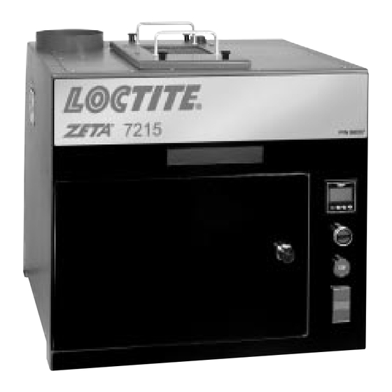
- Page 1 ® EQUIPMENT O P E R A T I O N M A N U A L Loctite ® Combined Manual High Intensity Cure Chamber Zeta 7215 ® 98007 Mercury Arc Lamp Zeta 7216 ® 98008 Electrodeless Lamp...
-
Page 2: Table Of Contents
Contents Zeta® 7215 Mercury Arc Chamber Page No. For Your Safety ............2 Introduction . - Page 3 Zeta ® 7215 Mercury Arc Ultraviolet Curing Chamber Instruction Manual 98007 Loctite ® Zeta ® 7215 High Intensity Cure Mercury Arc Chamber WARNING ULTRAVIOLET LIGHT This unit has been designed to prevent user exposure to UV light. 7215 READ OPERATOR'S MANUAL BEFORE USE...
-
Page 4: For Your Safety
4. Prior to any attempt at servicing, turn power off and remove power from all of the system components. 5. When changing lamp, allow 15 minutes for the lamp to cool prior to removing. Ultraviolet safety is the responsibility of the user. When in doubt about ultraviolet safety, consult a Loctite technical specialist at 1-800-LOCTITE (562-8483). -
Page 5: Introduction
DESCRIPTION The system is a bench top ultraviolet source designed for a wide range of Loctite ® ultraviolet curing adhesives and coatings. The unit is suitable for laboratory use or production requirements. -
Page 6: Items Supplied
Introduction, cont. ITEMS SUPPLIED 1. Cure Chamber Base and Lamp Adapter Assembly LOCTITE PART # 984130 2. 6" Mercury Arc Lamp Power Supply LOCTITE PART # 984132 3. 6" Mercury Arc Lamp Irradiator Assembly LOCTITE PART # 984134 4. Equipment Manual... -
Page 7: Installation & Start-Up
Installation & Start-Up INSTALLATION Refer to the installation diagram on the next page. The diagram gives the exterior dimensions of the High Intensity Cure Chamber and the Power Supply. Allow six inches of clearance around the unit for air circulation and cable connections. Air is drawn from the bottom of the Chamber and exhausted from the top out of the exhaust duct. -
Page 8: Space & Utility Requirements
Installation & Start-Up, cont. SPACE & UTILITY REQUIREMENTS Figure 1. Top View INTERLOCK CABLE POWER INPUT CORD POWER INPUT CORD Electrical Service Requirements 120 Volts 20 Amp Circuit High Inrush Magnetic Breaker HIGH VOLTAGE LAMP CABLE 120 Volts 15 Amp Circuit WARNING Remove power from all system components prior to servicing. -
Page 9: Mercury Lamp Installation & Replacement
CERAMIC INSULATORS 5. Connect the wires on the lamp to ceramic insulators. 6. Reinstall the lamp module. 7. Press the hourmeter reset on the back of the power supply. Lamp Loctite Part # 983091 SCREWS SCREWS Figure 4. Lamp Module... -
Page 10: Control & Operation
After the shutter closes the ZETA ® 7010 can be removed from the chamber and intensity or total energy read on the digital display. Contact your Loctite representative at 1-800-LOCTITE for the ZETA ® 7010 Puck Radiometer part number 98001. -
Page 11: Illustration Of Controls
Control and Operation, cont. ILLUSTRATION OF CONTROLS MAIN POWER ELAPSED TIME HIGH MODE CONTROL POWER STANDBY MODE LAMP POWER CAUTION ULTRAVIOLET IRRADIATORS EMIT RADIATION WHICH IS HARMFUL TO EYES AND SKIN. GREAT CARE MUST BE TAKEN TO INSURE THAT PERSONNEL ARE NOT EXPOSED TO DIRECT OR REFLECTED RADIATION. -
Page 12: Chamber Door Knob
Control & Operation, cont. CHAMBER DOOR KNOB WARNING ULTRAVIOLET LIGHT This unit has been designed to prevent user exposure to UV light. 7215 READ OPERATOR'S MANUAL BEFORE USE P/N 98007 CYCLE TIMER CYCLE START Chamber Interlock CYCLE STOP CHAMBER POWER Figure 5. -
Page 13: Maintenance
Maintenance ALWAYS REMOVE POWER FROM ALL UNITS CONNECTED TO THE SYSTEM PRIOR TO THE START OF ANY SERVICING! With proper care and maintenance, the U.V. lamp can be expected to have a useful life of approximately 1,000 hours. To install or change the lamp refer to section 3.3 in this manual entitled Mercury Lamp Installation. -
Page 14: Troubleshooting
Troubleshooting SYMPTOM POSSIBLE CAUSE ACTION System does not Open Interlock switch Check chamber door lamp turn on module four retainers Open fuse Fuse in Chamber U.V. Lamp does Open fuse Fuse in power supply not light Lamp failure Replace Lamp Cure speed declines End of Lamp’s useful life Replace Lamp... -
Page 15: Warranty
A claim of defect in materials or workmanship in any Products shall be allowed only when it is submitted to Loctite in writing within one month after discovery of the defect or after the time the defect should have reasonably have been discovered and in any event, within twelve months after the delivery of the Products to the purchaser excluding the Lamp. - Page 17 Zeta 7216 ® Electrodeless Lamp Ultraviolet Curing Chamber Instruction Manual 98008 Loctite ® Zeta ® 7216 High Intensity Cure Electrodeless Lamp Chamber WARNING ULTRAVIOLET LIGHT This unit has been designed to prevent user exposure to UV light. 7216 READ OPERATOR'S MANUAL BEFORE USE...
-
Page 18: For Your Safety
4. Prior to any attempt at servicing, turn the power off and remove power from all of the system components. 5. When changing the lamp, allow 15 minutes for the lamp to cool prior to removing. Ultraviolet safety is the responsibility of the user. When in doubt about ultraviolet safety, consult a Loctite technical specialist at 1-800-LOCTITE (562-8483). -
Page 19: Introduction
(F300S/F300SQ), be carefully read before any attempt to install or operate the equipment. DESCRIPTION The system is a bench top ultraviolet source designed for a wide range of Loctite ® ultraviolet curing adhesives and coatings. The unit is suitable for laboratory use or low production requirements. -
Page 20: Items Supplied
Introduction, cont. ITEMS SUPPLIED 1. Cure Chamber Base and Lamp Adapter Assembly LOCTITE PART # 984136 2. Electrodeless Lamp power Supply Assembly, 208 VOLT LOCTITE PART # 984138 3. Electrodeless Lamp Irradiator Assembly LOCTITE PART # 984139 4. RF Detector Cable LOCTITE PART # 984158 5. -
Page 21: Installation & Start-Up
Refer to the Electrodeless Lamp manual supplied along with this manual. This manual should be referred to for service requirements for the lamp and the power supply. This power supply has been configured for Loctite. The configuration enables the Alternate Function for K5 described in the Electrodeless Lamp manual under SETUP. -
Page 22: Space & Utility Requirements
Installation & Start-Up, cont. SPACE & UTILITY POWER INPUT CORD REQUIREMENTS POWER INPUT C Figure 9. Top View Electrical Service Requirements 220 Volt 15 Amp Circuit Single Phase 21 1/2 120 Volts 15 Amp Circuit P/N 984138 Configured Specifically For Use With This Cure Chamber LB-11003 DOOR SWINGS FROM RIGHT TO LEFT... -
Page 23: Control & Operation
6. Open the Chamber Door and adjust the shelf for desired intensity. The maximum ultraviolet intensity is available at the top of the chamber and the minimum at the bottom shelf position. if you are unsure about the proper shelf setting utilize a Loctite ®... -
Page 24: Illustration Of Controls
Control and Operation, cont. ILLUSTRATION OF CONTROLS POWER LAMP CONTROL LAMP ON PHOTOCELL TEST POINTS STANDBY (0-12 VDC) LAMP OFF /RESET LAMP OUT PWR IMBAL PWR ERROR UNIT PS TEMP BLWR PRESSURE SYS BLWR MAGNETRON EXT INTLK SYSTEM TEST POINTS RF INTLK P300M POWER SUPPLY INDICATOR TEST... -
Page 25: Chamber Door Knob
Control and Operation, cont. CHAMBER DOOR KNOB WARNING ULTRAVIOLET LIGHT Chamber Interlock This unit has been designed to prevent user exposure to UV light. 7216 READ OPERATOR'S MANUAL BEFORE USE P/N 98008 CYCLE TIMER CYCLE START CYCLE STOP CHAMBER POWER Adjusts Chamber Interlock Tension Figure 11. -
Page 26: Maintenance
Maintenance ALWAYS REMOVE POWER FROM ALL UNITS CONNECTED TO THE SYSTEM PRIOR TO THE START OF ANY SERVICING! In addition to this manual, a manual (F300S/F300SQ) for the Electrodeless Lamp and Power Supply was shipped with the system. For all servicing and maintenance of the lamp or power supply, this manual (F300S/F300SQ) should be referred to. -
Page 27: Specifications
Specifications Lamp Electrodeless Lamp "H" Bulb 1,800 Watts 6 inch lamp 300 Watts/inch. Power Supply 208 VAC, 15A, 60 HZ, 1 Phase Power Supply Fuse 15 A Power Supply Consumption 2,400 Watts Dimensions See Installation Drawing System Shipping Weight 255 Lbs. Power Supply Circuit Breaker Chamber Fuse Chamber Drive Fuse... -
Page 28: Warranty
A claim of defect in materials or workmanship in any Products shall be allowed only when it is submitted to Loctite in writing within one month after discovery of the defect or after the time the defect should have reasonably have been discovered and in any event, within twelve months after the delivery of the Products to the purchaser excluding the Lamp. -
Page 29: Appendix
CABLES FOR FUSION UNIT (YEL) JACK 105B (ORG) MOTOR (BLK) CABLE FROM MERCURY POWER SUPPLY BACK OF INTERLOCK PLUG WIRING DIAGRAM for LOCTITE SHUTTER BOX ITEM DESCRIPTION PART NO. QTY. 4 POLE N.O. RELAY 984188 4 POLE (2) N.O. (2) N.C. RELAY 984168 4 POLE (2) N.O. -
Page 30: Wiring Diagram For The Mercury Arc Power Supply
Appendix WIRING DIAGRAM FOR THE MERCURY ARC POWER SUPPLY BALLAST (9526) F1 FUSE INTERLOCK BETWEEN POWER SUPPLY AND CURE CHAMBER I.T. INTERVAL TIMER LAMP INTERLOCK DELAY TIMER 35 AMP CONTACTOR P2/S2 P1/S1 METER INTERLOCK RESET MOMENTARY BUTTON ITEM QTY. DESCRIPTION PART NUMBER MERCURY ARC POWER SUPPLY INTERVAL TIMER 984179... - Page 32 Loc. Tulpetlac, C.P. 55090 Ecatepac de Morelos, Edo. de México México Loctite Brazil Av. Prof. Vernon Krieble, 91 06690-11-Itapevi Loctite and Zeta are trademarks of Loctite Corporation, U.S.A. © Copyright 2000. Loctite Corporation. All rights reserved. P/N984135 Rev. A – 7/00...
Need help?
Do you have a question about the Zeta 7215 and is the answer not in the manual?
Questions and answers