Table of Contents
Advertisement
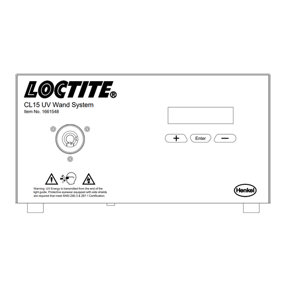
CL15 UV Wand System
Item No. 1661548
Warning: UV Energy is transmitted from the end of the
light guide. Protective eyewear equipped with side shields
are required that meet ANSI Z80.3 & Z87.1 Certification.
Loctite® CL15 UV Curing Wand System
Part Number: 1661548
EQUIPMENT
Operation Manual
_
+
Enter
Advertisement
Table of Contents

Subscribe to Our Youtube Channel
Related Manuals for Loctite CL15 UV


Summary of Contents for Loctite CL15 UV
- Page 1 Item No. 1661548 Enter Warning: UV Energy is transmitted from the end of the light guide. Protective eyewear equipped with side shields are required that meet ANSI Z80.3 & Z87.1 Certification. Loctite® CL15 UV Curing Wand System Part Number: 1661548...
-
Page 2: Table Of Contents
TABLE OF CONTENTS PLEASE OBSERVE THE FOLLOWING EMPHASIZED SECTION ITEMS SUPPLIED FOR YOUR SAFETY FIELD OF APPLICATION, (INTENDED USAGE) DESCRIPTION THEORY OF OPERATION OPERATING ELEMENTS AND CONNECTIONS TECHNICAL DATA INSTALLATION SPACE REQUIREMENTS CONNECTIONS OPERATING THE UNIT INSERTING AND REMOVING LIGHT GUIDES INSTALLING SINGLE LIGHT GUIDE BALANCING MULTI-POLE LIGHT GUIDES CARE AND MAINTENANCE... -
Page 3: Please Observe The Following
Please Observe the Following 1.1 Emphasized Sections WARNING! Refers to safety regulations and required measures that protect the operator or other persons from injury or danger to life. Caution! Emphasizes what must be done or avoided so that the unit or other property is not damaged. -
Page 4: Field Of Application, (Intended Usage)
The unit may be repaired only by a Loctite® authorized service technician. Field of Application, (Intended Usage) This Loctite® UV CL15 Wand System is designed for use with Loctite products that cure when exposed to ultraviolet light produced by the unit. The UV energy is directed towards the product through a liquid filled light guide that is ordered separately. -
Page 5: Operating Elements And Connections
The front panel is a membrane control pad with an LCD display. The keypad controls all the major operating features. Light Guide Receptacle Back Lit LCD Display CL15 UV Wand System Item No. 1661548 Enter Warning: UV Energy is transmitted from the end of the light guide. - Page 6 Description (continued) LCD Display The digital display serves as the user interface. It is used to set and view the shutter ON/OFF time, number of cycles, lamp hours, and system hours. During a cure cycle the time and duration will be shown counting down for user viewing. ENTER Button The OK button allows the user to scroll through the levels of set-up parameters.
- Page 7 Description (continued) Back Panel Intake Fan Main Power Switch Exhaust Fan MADE IN USA INPUT: 90-240VAC 50/60Hz XS-1 T4AL250V CLEAN FILTER REGULARLY Foot Switch Power Entry Module Connection Cooling Fans The fan system is used to maintain the optimum temperature of the lamp while cooling the optics and electronics.
- Page 8 Description (continued) Lamp Housing This area contains the optical transmission assembly, bulb, reflector and electrical lamp connections. UV Bulb/Reflector Assembly Shutter Assembly UV Bulb Connector Filter Holder Bulb Retainer Clips...
- Page 9 Description (continued) Shutter Assembly The Shutter Assembly is a shutter plate that is connected to a positive open, spring return, rotary solenoid for efficient control and safety. The shutter is also connected to an interlock switch located on the light guide receptacle where the proximal end of the light guide is inserted.
-
Page 10: Technical Data
Technical Data Energy Requirements Input Voltage Ranges: 90 to 240 VAC Input frequency Range: 50 to 60 Hz Auxiliary Output Voltage: 24 volts DC, nominal Main fuse located in power module in rear of unit: 4A T/250V, 5mm Dimensions Housing: Approximately 12 ½ inch W x 9 ¾ inch D x 5 ½ inch H Weight: Approximately 7 pounds UV Output Characteristics Initial UV output: up to 15 W/sq.cm, typical. -
Page 11: Installation
Installation Space Requirements A space of 12" wide x 16" deep x 9" height is required. It is important to have at least 8 inches of space behind the unit to insure proper airflow. Curing Wand System only needs to be connected to a 120V/60Hz outlet to operate. Caution! Do not block the intake and exhaust fans located on the back of the housing. - Page 12 Operating the Unit, (continued) At this time the operating parameters can be changed, or the existing parameters can be utilized. The footswitch can now be pressed or PLC output operated to initiate the operation of the curing unit. Using Foot Switch / Remote Device The shutter can be actuated using a foot switch or by other external devices such as a PLC.
- Page 13 Operating the Unit, (continued) Shutter ON Time Setting The first parameter that can be changed is the amount of time that the shutter is open during a cycle. The time can be increased or decreased using the (+) or (-) buttons. The shutter open time can be set with the following limits: Time Base Min Time...
-
Page 14: Inserting And Removing Light Guides
Operating the Unit, (continued) Lamp Hour Reset The lamp hour meter is used to keep track of the time that the given bulb has been in service. Once the bulb has been changed the lamp hour meter should be reset to accurately track the service of the new bulb. - Page 15 Tighten the set screw on to the light guide, (do not over tighten). Set shutter timer to between 2 and 5 seconds. ® Insert the one of the pole ends of the light guide into a Loctite 7020 UV Spot Radiometer, P/N 1406024.
-
Page 16: Care And Maintenance
It is recommended that the end of the light guide be positioned no closer than ½ inch from the Loctite® product being cured. The heat transmitted by the lamp can adversely affect the properties of the cured product or possibly cause damaged to the part surface. - Page 17 3. Using a 3/32” Allen wrench, loosen the four button head screws that are on the sides of the top cover. 4. Lift the cover straight up off of the chassis. This will allow access to the bulb reflector assembly. 5.
-
Page 18: Trouble Shooting
Trouble Shooting WARNING! Parts may be hot. If unit was running, allow time for adequate cool down. Exercise caution when touching internal parts. Condition Correction Unit Does Not Turn On Check power at wall. Check condition of line cord. Check line cord connections. Check fuse. -
Page 19: Pin Connections
Pin Connections Replacement Parts and Accessories Loctite® Part Description Number 1664246 Replacement Lamp Module 983677 Single End Light Guide (5 mm x 1M) 983684 2 Pole Light Guide (3 mm x 1M) 951681 Single Light Guide (5 mm x 1.5M) -
Page 20: Warranty
Warranty Henkel expressly warrants that all products referred to in this Instruction Manual for the CL15 UV Curing Wand System, (hereafter called “Product”), shall be free from defects in materials and workmanship. Liability for Henkel shall be limited, as its option, to replacing those Products which are shown to be defective in either materials or workmanship or to credit the purchaser the amount of the purchase price thereof (plus freight and insurance charges paid therefore by the user). - Page 21 Automotive / Metals HQ Rua Karl Huller, 136 – Jd. 32100 Stephenson Hwy. Canhema 09941-410 www.loctite.com Madison Heights, MI 48071 Diadema/SP, Brazil ® and ™ designate trademarks of Henkel Corporation or its affiliates. ® = registered in the U.S. and elsewhere. © Henkel Corporation, 2009.
Need help?
Do you have a question about the CL15 UV and is the answer not in the manual?
Questions and answers