Siemens Cerberus PACE Mounting & Installation
System
Hide thumbs
Also See for Cerberus PACE:
- Manual (173 pages) ,
- Operation manual (66 pages) ,
- Operating manual (42 pages)
Table of Contents
Advertisement
Quick Links
Download this manual
See also:
Operating Manual
Advertisement
Table of Contents

Subscribe to Our Youtube Channel
Related Manuals for Siemens Cerberus PACE


Summary of Contents for Siemens Cerberus PACE
- Page 1 Cerberus PACE System Mounting Installation Building Technologies A6V10430579_en--_a 2018-06-08 Control Products and Systems...
- Page 2 Issued by: Siemens Switzerland Ltd. Building Technologies Division International Headquarters Theilerstrasse 1a CH-6300 Zug Tel. +41 58 724-2424 www.siemens.com/buildingtechnologies Edition: 2018-06-08 Document ID: A6V10430579_en--_a © Siemens Switzerland Ltd, 2018 2 | 24 Siemens Schweiz AG A6V10430579_en--_a Fire Safety 2018-06-08...
-
Page 3: Table Of Contents
Wiring the mains supply line ................. 18 4.2.1 1-phase mains connection ............. 19 4.2.2 3-phase mains connection ............. 20 Wiring the batteries ................... 21 Power supply PP2003 ................... 21 Power supply PP2004 ................... 23 3 | 24 Siemens Schweiz AG A6V10430579_en--_a Fire Safety 2018-06-08... - Page 4 Figure 3: Wiring diagram for 1x battery set ............21 Figure 4: Wiring diagram for 2x battery sets ............22 Figure 5: Wiring diagram for the batteries in the PP2004 ........23 4 | 24 Siemens Schweiz AG A6V10430579_en--_a Fire Safety 2018-06-08...
-
Page 5: About This Document
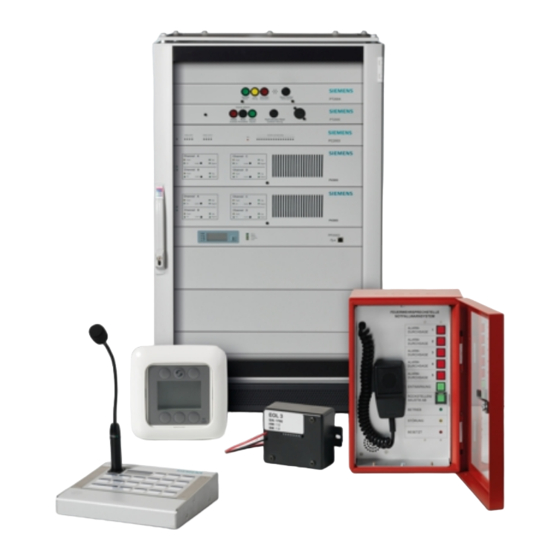
Should you require another copy of this document, please contact the Customer Support Center, phone +49 89 9221-8000. Goal and purpose This document describes how to mount and install a 'Cerberus PACE' network- based voice alarm and announcement system for the following tasks: ●... - Page 6 Carries out all maintenance work. ● Has obtained suitable specialist training for the function and for the ● Checks that the products are in products. perfect working order. ● Searches for and corrects malfunctions. 6 | 24 Siemens Schweiz AG A6V10430579_en--_a Fire Safety 2018-06-08...
- Page 7 'Menu bar' > 'Help' > 'Help topics' ↑ Text Identification of a glossary entry Supplementary information and tips The 'i' symbol identifies supplementary information and tips for an easier way of working. 7 | 24 A6V10430579_en--_a Siemens Schweiz AG Fire Safety 2018-06-08...
-
Page 8: Applicable Documents
About this document Applicable documents 1.1 Applicable documents You will find more information on the 'Cerberus PACE' system and its components in the following documents: Title Document ID IT security policies Cerberus PACE – IT security policies* A6V11439692 System documentation Cerberus PACE –... -
Page 9: Safety
' identifies a possibly harmful situation or possible damage to property that may result from non that may result from non-observance. ' NOTICE NOTICE ' does not relate to possible bodily injury. 9 | 24 A6V10430579_en--_a Siemens Schweiz AG Fire Safety 2018-06-08... -
Page 10: Safety Regulations For The Method Of Operation
National standards, regulations and legislation National standards, regulations and legislation Siemens products are developed and produced in compliance with the relevant Siemens products are developed and produced in compliance with the relevant Siemens products are developed and produced in compliance with the relevant European and international safety standards. - Page 11 Written confirmation must be obtained from malfunctioning and safety risks. Written confirmation must be obtained from Siemens and the corresponding safety bodies for modifications or additions. ens and the corresponding safety bodies for modifications or additions.
- Page 12 Disregard of the safety regulations Before they are delivered, Siemens products are tested to ensure they function correctly when used properly. Siemens disclaims all liability for damage or injuries caused by the incorrect application of the instructions or the disregard of danger warnings contained in the documentation.
-
Page 13: Responsibility Of The Operator
– for example, in rooms with a high concentration of dust, high levels of air humidity, or significant temperature fluctuations. 2.4 Standards and directives complied with A list of the standards and directives complied with is available from your Siemens contact. 13 | 24 A6V10430579_en--_a... -
Page 14: Cyber Security Disclaimer
Siemens’ portfolio undergoes continuous development to make it more secure. Siemens strongly recommends that updates are applied as soon as they are available and that the latest versions are used. Use of versions that are no longer supported, and failure to apply the latest updates may increase your exposure to cyber threats. -
Page 15: Preparatory Work
Check that the delivery units are complete according to the details for ordering. Check that the delivery units are complete according to the details for ordering. Check that the delivery units are complete according to the details for ordering. 15 | 24 A6V10430579_en--_a Siemens Schweiz AG Fire Safety 2018-06-08... -
Page 16: Electrical Supply Lines
In order to avoid an unintentional shutdown, the mains supply line must not be routed via a switch. See also 1 Safety regulations for the method of operation [➙ 10] 16 | 24 Siemens Schweiz AG A6V10430579_en--_a Fire Safety 2018-06-08... -
Page 17: Mounting/Installation
6. The cabinet is ready for installation and the swivel frame can now be opened. The cabinet is ready for installation and the swivel frame can now be opened. The cabinet is ready for installation and the swivel frame can now be opened. 17 | 24 A6V10430579_en--_a Siemens Schweiz AG Fire Safety 2018-06-08... -
Page 18: Wiring The Mains Supply Line
Live cables must not be routed in the same cable ducts as data cables. ive cables must not be routed in the same cable ducts as data cables. ive cables must not be routed in the same cable ducts as data cables. 18 | 24 Siemens Schweiz AG A6V10430579_en--_a Fire Safety 2018-06-08... -
Page 19: 1-Phase Mains Connection
1. Working with the mains supply line, start by connecting the protective conductor with the yellow/green wire to the free 'PE' ground terminal. 2. Connect the blue neutral conductor to terminal 'N'. 3. Connect the brown outer conductor to terminal 'L1'. 19 | 24 A6V10430579_en--_a Siemens Schweiz AG Fire Safety 2018-06-08... -
Page 20: 3-Phase Mains Connection
'PE' ground terminal. 2. Connect the blue neutral conductor to a free terminal 'N'. 3. Connect each of the brown outer conductors to a free terminal: 'L1', 'L2', and 'L3'. 20 | 24 Siemens Schweiz AG A6V10430579_en--_a Fire Safety 2018-06-08... -
Page 21: Wiring The Batteries
2x connections for external error display ● 3x connections with potential-free relay contacts for supply system and battery monitoring ● 1x Ethernet port Figure 3: Wiring diagram for 1x battery set 21 | 24 A6V10430579_en--_a Siemens Schweiz AG Fire Safety 2018-06-08... -
Page 22: Figure 4: Wiring Diagram For 2X Battery Sets
The minimum distance between two battery cable sets must be 15 cm. ● The temperature sensor must be positioned directly next to the batteries. ● The battery separators must be mounted as close as possible to the battery terminals. 22 | 24 Siemens Schweiz AG A6V10430579_en--_a Fire Safety 2018-06-08... -
Page 23: Power Supply Pp2004
● The temperature sensor must be positioned directly next to the batteries. ● The battery separator must be mounted as close as possible to the battery's positive terminal. 23 | 24 A6V10430579_en--_a Siemens Schweiz AG Fire Safety 2018-06-08... - Page 24 Issued by © Siemens Switzerland Ltd, 2018 Siemens Switzerland Ltd Technical specifications and availability subject to change without notice. Building Technologies Division International Headquarters Theilerstrasse 1a CH-6300 Zug +41 58 724 2424 www.siemens.com/buildingtechnologies Document ID: A6V10430579_en--_a Edition: 2018-06-08...
Need help?
Do you have a question about the Cerberus PACE and is the answer not in the manual?
Questions and answers