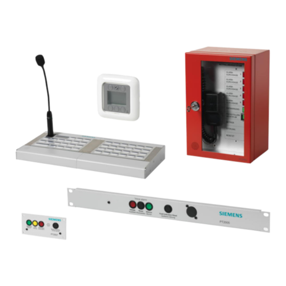
Siemens Cerberus PACE Operation Manual
Public address and controlled evacuation
Hide thumbs
Also See for Cerberus PACE:
- Manual (173 pages) ,
- Operation manual (57 pages) ,
- Operating manual (42 pages)

Related Manuals for Siemens Cerberus PACE


Summary of Contents for Siemens Cerberus PACE
- Page 1 Cerberus PACE Public Address and Controlled Evacuation Operation Manual A6V10430571_en--_e Smart Infrastructure 2024-03-12...
- Page 2 Offenders will be held liable for payment of damages. All rights created by patent grant or registration of a utility model or design patent are reserved. Issued by: Siemens Switzerland Ltd. Smart Infrastructure Global Headquarters Theilerstrasse 1a CH-6300 Zug Tel.
-
Page 3: Table Of Contents
Table of contents About this document ..................5 Applicable documents ..................8 Technical terms and abbreviations ..............9 Revision history ....................9 Safety ......................10 Safety notes ....................10 Safety regulations for the method of operation ..........11 System owner ....................13 Function test / system acceptance / maintenance ........ - Page 4 11.3 Indicator PT2008-A1 ..................45 System operating unit (19") PT2010-A1 ............ 46 12.1 Operating functions PT2010-A1 ..............46 12.2 Operation PT2010-A1 ................... 47 12.3 Indicator PT2010-A1 ..................48 System status indicator (19") PT2004-A1 ..........49 13.1 Operating functions PT2004-A1 ..............49 13.2 Operation PT2004-A1 ...................
-
Page 5: About This Document
The information contained in this document is valid for Cerberus PACE. WARNING The 'Cerberus PACE' system is a Class A product. Operation of this equipment in a residential environment could cause radio interference. If so, the user must be required to take adequate measures. -
Page 6: Document Identification
About this document Applicable documents Target group Activity Qualification ● ● Commissioning personnel Configures the product at the place Has obtained suitable specialist of installation according to training for the function and for the customer-specific requirements. products. ● ● Checks the product operability and Has attended the training courses releases the product for use by the for commissioning personnel. - Page 7 About this document Applicable documents 'Text' Quote, exact match <Button Identification of buttons > > Indicates a link and identifies steps in a sequence, e.g., 'Menu bar' > 'Help' > 'Help topics' ↑ Text Identifies a glossary entry Additional information and tips The 'i' symbol identifies additional information and tips to simplify the procedure.
-
Page 8: Applicable Documents
About this document Applicable documents 1.1 Applicable documents You will find more information on the Cerberus PACE system and its components in the following documents: Title Document ID IT security policies IT security policies A6V11439692 System documentation Planning A6V11244536 'PACE-Design' – Configuration... -
Page 9: Technical Terms And Abbreviations
1.2 Technical terms and abbreviations You will find details of technical terms and abbreviations in the 'Glossary' chapter. Harmonized wording throughout the document: ● Device: any product which can be connected to the Cerberus PACE system ● Component: a Cerberus PACE device ●... -
Page 10: Safety
Safety Safety notes 2 Safety 2.1 Safety notes The safety notices must be observed in order to protect people and property. The safety notices in this document contain the following elements: ● Symbol for danger ● Signal word ● Nature and origin of the danger ●... -
Page 11: Safety Regulations For The Method Of Operation
2.2 Safety regulations for the method of operation National standards, regulations and legislation Siemens products are developed and produced in compliance with the relevant European and international safety standards. Should additional national or local safety standards or legislation concerning the planning, mounting, installation,... - Page 12 Modifications to the system design and the products Modifications to the system and to individual products may lead to faults, malfunctioning and safety risks. Written confirmation must be obtained from Siemens and the corresponding safety bodies for modifications or additions. Components and spare parts ●...
-
Page 13: System Owner
Disregard of the safety regulations Before they are delivered, Siemens products are tested to ensure they function correctly when used properly. Siemens disclaims all liability for damage or injuries caused by the incorrect application of the instructions or the disregard of danger warnings contained in the documentation. -
Page 14: Standards And Directives Complied With
---- End EN 55032 section 4 ---- WARNING The 'Cerberus PACE' system is a Class A product. Operation of this equipment in a residential environment could cause radio interference. If so, the user must be required to take adequate measures. -
Page 15: Cyber Security Disclaimer
Siemens’ portfolio undergoes continuous development to make it more secure. Siemens strongly recommends that updates are applied as soon as they are available and that the latest versions are used. Use of versions that are no longer supported, and failure to apply the latest updates may increase your exposure to cyber threats. -
Page 16: Operating Conditions
Operating conditions Operating condition indicators 3 Operating conditions The ↑ voice alarm control and indicating equipment (VACIE) or voice alarm system has the following operating conditions: ● Quiescent condition ● Voice alarm condition ● Fault warning condition 3.1 Operating condition indicators Indicating element colors The light-emitting indicating elements display operating conditions as follows: ↑... -
Page 17: Operating Elements In The System
Operating terminals 4 Operating elements in the system The operating elements in a Cerberus PACE voice alarm system are the call stations and operating terminals with which you can make live announcements and play emergency tones and recorded messages in a targeted manner. - Page 18 Operating elements in the system Operating terminals PT2004-A1 'System state indicator (19")' ● EN 54-16-compliant indicator panel for visual and acoustic status messages ● Color-coded visual indicators: operation, fault, and alarm – <Operating / Betrieb>: green – <Fault / Störung>: yellow –...
-
Page 19: Call Stations
PT2002-A1 'Fire brigade call station (AT)' ● Fire brigade call station with standard-compliant housing and control panel ● Full network participant in a Cerberus PACE system ● Pre-configured for Austrian F3033 standard ● Can be configured for other standards ●... - Page 20 19 configurable buttons and status indicators to control and monitor the Cerberus PACE system by users ● The buttons are basically freely operable ● Full network participant in a Cerberus PACE system ● Insertable labels for custom buttons and indicator identification ● 2-line text display ●...
- Page 21 'Desk call station (RS485, 8+1)' ● Desk call station with electret condenser microphone and gooseneck ● 8 configurable and illuminated zone buttons plus a talk button to control and monitor the Cerberus PACE system by users ● Buttons are freely operable ● Monitored microphone ●...
- Page 22 ● Desk call station with electret condenser microphone and gooseneck ● 3 configurable and illuminated zone buttons plus a talk button to control and monitor the Cerberus PACE system by users ● Buttons are freely operable ● Balanced audio transmission, analog ●...
-
Page 23: Access Levels
Access levels 5 Access levels The access level describes one of several conditions of voice alarm control and indicating equipment (VACIE) in which an appropriately authorized user can have access to or a view of the following functions on the system: ●... -
Page 24: Voice Alarms
Voice alarms Activate a voice alarm 6 Voice alarms 6.1 Activate a voice alarm A voice alarm is like a regular announcement but marked as 'Alarm' message. A voice alarm can be activated by: ● "Start voice alarm" button at PT2005 or PT2010 ●... -
Page 25: Fire Brigade Call Station Pt2002-A1 And Pt2003-A1
Fire brigade call station PT2002-A1 and PT2003-A1 Signalization in voice alarm condition 7 Fire brigade call station PT2002-A1 and PT2003-A1 This chapter describes the operating functions of the ● 'Fire brigade call station (AT)' PT2002-A1 and ● 'Fire brigade call station (485, AT)' PT2003-A1 Microphone with <Push-To-Talk>... -
Page 26: Operating Functions Pt2002-A1 And Pt2003-A1
Fire brigade call station PT2002-A1 and PT2003-A1 Operating functions PT2002-A1 and PT2003-A1 7.1 Operating functions PT2002-A1 and PT2003-A1 Function Design Carry out a manual 1. Lift the microphone (1) announcement / trigger an 2. Press and hold the <Push-To-Talk> button (1) evacuation 3. -
Page 27: Operation Pt2002-A1
Use the PACE-Design MP2.0 SR2 or later versions ● Use the PT2002-A1 FS03 or later versions, or upgrade the older PT2002-A1 according to 'MI Cerberus PACE Fire Fighter Call Station - Switch at Microphone Hook' ● The PT2002-A1 is configured without using the hook-off switch and with the <Push-To-Talk>... - Page 28 Fire brigade call station PT2002-A1 and PT2003-A1 Operation PT2002-A1 2. Press the <Push-To-Talk> button on the microphone and hold it while talking into the microphone at a normal sound level. Active announcements and background music are deactivated. If configured, a pre-announcement message is played and the engaged LED <BESETZT>...
- Page 29 Recur fault messages The fault LED <STÖRUNG> lights up again. The fault in the system has not been rectified. ◈ Inform Siemens customer support. Request that maintenance be carried out by technical personnel. A6V10430571_en--_e 29 | 66...
-
Page 30: Operation Pt2003-A1
Fire brigade call station PT2002-A1 and PT2003-A1 Operation PT2003-A1 7.3 Operation PT2003-A1 Transmit a manual announcement / Trigger an evacuation with a manual announcement The manual announcement function of the PT2003-A1 depends on the configuration and the software version. Variant A: without using the hook-off switch ●... - Page 31 Recur fault messages The fault LED <STÖRUNG> lights up again. The fault in the system has not been rectified. ◈ Inform Siemens customer support. Request that maintenance be carried out by technical personnel. A6V10430571_en--_e 31 | 66...
-
Page 32: Desk Call Station (19 Buttons) Pt2001-A1
Desk call station (19 buttons) PT2001-A1 Operating functions PT2001-A1 and PTO2001-A1 8 Desk call station (19 buttons) PT2001-A1 This chapter describes the operation of the ‘Desk call station (19 buttons)’ PT2001- A1 and the connected ‘Desk call station extension (24 buttons)’ PTO2001-A1. Microphone LED 'ONLINE' / Fault Display... -
Page 33: Operation Pt2001-A1 And Pto2001-A1
Desk call station (19 buttons) PT2001-A1 Operation PT2001-A1 and PTO2001-A1 Function Design Remedy faults ◈ Press the button (3) labeled <RESET / ACOUSTIC OFF> Give the all-clear command ◈ Press the button (3) labeled <ALL-CLEAR> 8.2 Operation PT2001-A1 and PTO2001-A1 Transmit a manual announcement / Trigger an evacuation with a manual announcement ●... - Page 34 The fault message is reset. Recur fault messages The LED 'FAULT' lights up again. The fault in the system has not been rectified. ◈ Inform Siemens customer support. Request that maintenance be carried out by technical personnel. 34 | 66 A6V10430571_en--_e...
-
Page 35: Indicator Pt2001-A1 And Pto2001-A1
Desk call station (19 buttons) PT2001-A1 Indicator PT2001-A1 and PTO2001-A1 8.3 Indicator PT2001-A1 and PTO2001-A1 Color Status Default Description LED ON (5) Green System is in regular operating mode Call station is in alarm mode with activated alarm key or station priority is configured to 8 or higher Call station is not working (no power) LED Online (4) - Page 36 Desk call station (19 buttons) PT2001-A1 Indicator PT2001-A1 and PTO2001-A1 Color Status Default Description Microphone is not activated PLAY Sound Button (3) is configured as 'PLAY Sound' Green Sound is active Sound is not activated STOP Sound Button (3) is configured as 'STOP Sound' Always Record buffer Button (3) is configured as 'Record buffer'...
-
Page 37: Display Information Pt2001-A1
Desk call station (19 buttons) PT2001-A1 Display information PT2001-A1 8.4 Display information PT2001-A1 #1003 v0.9B26 On:178d,10:55:19 Fig. 1: Example of a display view of PT2001-A1 Display Description #1003 Configured station ID address v0.9B26 Current firmware version On:178d,10:55:19 Power on time NOTICE The information shown on the display cannot be changed, modified or turned off. -
Page 38: Key Switch Extension Pto2002-A1 And Pto2003-A1 For Desk Call Station Pt2001-A1
Key switch extension PTO2002-A1 and PTO2003-A1 for desk call station PT2001-A1 Display information PT2001-A1 9 Key switch extension PTO2002-A1 and PTO2003-A1 for desk call station PT2001- This chapter describes the operation of the key switch extensions ‘Desk call station extension (Kaba)’ PTO2002-A1 and ‘Desk call station extension (Nordic)’ PTO2003-A1 connected to PT2001-A1. -
Page 39: Operating Functions Pto2002-A1 And Pto2003-A1
Key switch extension PTO2002-A1 and PTO2003-A1 for desk call station PT2001-A1 Operating functions PTO2002-A1 and PTO2003-A1 9.1 Operating functions PTO2002-A1 and PTO2003- Unlock/lock the desk call station PT2001-A1 and connected PTO2001-A1 Function Design Unlock the call station ◈ Turn key switch with key to position 1 (horizontal) Lock the call station ◈... -
Page 40: Desk Call Station (Rs485, 8+1) Pt2009-A1 And Call Station Extension (Rs485, 8) Pto2006-A1
Desk call station (RS485, 8+1) PT2009-A1 and Call station extension (RS485, 8) PTO2006-A1 Operating functions PT2009-A1 10 Desk call station (RS485, 8+1) PT2009-A1 and Call station extension (RS485, 8) PTO2006-A1 Microphone Talk button Configurable buttons Speaker You can create and print the button identification in 'PACE-Design'. 10.1 Operating functions PT2009-A1 Function Design... -
Page 41: Indicator Pt2009-A1
Desk call station (RS485, 8+1) PT2009-A1 and Call station extension (RS485, 8) PTO2006-A1 Indicator PT2009-A1 2. Press the talk button for the manual announcement. The microphone is activated. 3. Talk into the microphone at a normal sound level. Active announcements and background music are deactivated in the selected zones. - Page 42 Desk call station (RS485, 8+1) PT2009-A1 and Call station extension (RS485, 8) PTO2006-A1 Indicator PT2009-A1 Color Status Default Description Green Zone is activated via the 'Talk' button and the station priority is set to 1-7 Zone is activated via the 'Talk' button and the station priority is set to 8 or higher Zone is activated via the 'PLAY Sound' Slow...
-
Page 43: Desk Call Station (Analog, 3+1) Pt2008-A1
Desk call station (analog, 3+1) PT2008-A1 Operating functions PT2008-A1 11 Desk call station (analog, 3+1) PT2008-A1 Microphone Talk button Configurable buttons You can create and print the button identification in 'PACE-Design'. 11.1 Operating functions PT2008-A1 Function Design Select a zone ◈... -
Page 44: Operation Pt2008-A1
Desk call station (analog, 3+1) PT2008-A1 Operation PT2008-A1 11.2 Operation PT2008-A1 Transmit a manual announcement ● Talk button configured as switch 1. Select a zone or several zones by pressing the relevant labeled buttons. Selected zone buttons light up. 2. -
Page 45: Indicator Pt2008-A1
Desk call station (analog, 3+1) PT2008-A1 Indicator PT2008-A1 11.3 Indicator PT2008-A1 Color Status Default Description Zone Button (2) is configured as 'Zone' Green Zone is selected Green Zone is activated via the 'Talk' button and the station priority is set to 1-7 Slow Zone is activated via the 'Logic control input' and the station priority... -
Page 46: System Operating Unit (19") Pt2010-A1
System operating unit (19") PT2010-A1 Operating functions PT2010-A1 12 System operating unit (19") PT2010-A1 Fault Power Supply Fault FUSE Fault EARTH System ON Fault Voice Alarm Fault NETWORK Fault BUS Fault AMP Fault MIC Silence Buzzer/LED Test Fault Speaker Circuit Start Voice Reset Voice Silence Voice... -
Page 47: Operation Pt2010-A1
The LED 'FAULT' lights up again. The fault in the system has not been rectified. ◈ Inform Siemens customer support. Request that maintenance be carried out by technical personnel. Perform an LED test No buzzer is active. -
Page 48: Indicator Pt2010-A1
System operating unit (19") PT2010-A1 Indicator PT2010-A1 12.3 Indicator PT2010-A1 Color Status Default Description Operating Green System is in regular operating mode System is not working Fault / Störung Yellow System has at least one fault No fault in the system Voice alarm / Sprachalarm A voice alarm is active in the system System is in quiescent state and no voice alarm is active... -
Page 49: System Status Indicator (19") Pt2004-A1
The LED 'FAULT' lights up again. The fault in the system has not been rectified. ◈ Inform Siemens customer support. Request that maintenance be carried out by technical personnel. Perform an LED test No buzzer is active. -
Page 50: Indicator Pt2004-A1
System status indicator (19") PT2004-A1 Indicator PT2004-A1 13.3 Indicator PT2004-A1 Color Status Default Description Operating Green System is in regular operating mode System is not working Fault Yellow System has at least one fault No fault in the system Voice alarm A voice alarm is active in the system System is in quiescent state and no voice alarm is active 50 | 66... -
Page 51: System Status Display (Door) Pt2007-A1
The LED 'FAULT' lights up again. The fault in the system has not been rectified. ◈ Inform Siemens customer support. Request that maintenance be carried out by technical personnel. Perform an LED test No buzzer is active. -
Page 52: Indicator Pt2007-A1
System status display (door) PT2007-A1 Indicator PT2007-A1 ◈ Press and hold the black <Buzzer reset/Test / Quittierung/Test> button for a few seconds to test the function of the buzzer and all LEDs. If there is no fault displayed, the LED test can be carried out. 14.3 Indicator PT2007-A1 Color Status... -
Page 53: Alarm Control Panel (19") Pt2005-A1
Alarm control panel (19") PT2005-A1 Operating functions PT2005-A1 15 Alarm control panel (19") PT2005-A1 <Initiate / Auslösen> indicator <Fault Indication Reset / button Quittierung Störung> button <Reset / Rückstellen> button Service socket <Silence /Stumm> indicator button 15.1 Operating functions PT2005-A1 Function Design Activate the alarm... -
Page 54: Operation Pt2005-A1
Alarm control panel (19") PT2005-A1 Operation PT2005-A1 15.2 Operation PT2005-A1 Activate the alarm ◈ Press the red indicator button <Initiate / Auslösen>. The alarm is activated in the system. The red indicator button <Initiate / Auslösen> is active. Reset the alarm manually ◈... -
Page 55: Remote Control Panel Pt2006-A1
Remote control panel PT2006-A1 Operating functions PT2006-A1 16 Remote control panel PT2006-A1 Player C VOL- MUTE VOL+ <Next channel in descending <Increase sound level> order> <Switch the output> <Mute> <Next channel in ascending order> 6 <Reduce sound level> 16.1 Operating functions PT2006-A1 Function Button Switch the output... -
Page 56: Operation Pt2006-A1
Remote control panel PT2006-A1 Operation PT2006-A1 16.2 Operation PT2006-A1 Switch the output ◈ Press the top middle button (2). Output is switched. Switch the channel ◈ Press the top right button (3). The next channel in ascending order is selected. ◈... -
Page 57: Power Supply Pp2003-A1
Power supply PP2003-A1 17 Power supply PP2003-A1 In case the power supply in PP2003-A1 detects an error e.g. 'battery fault' when the batteries are switched off, the internal buzzer of the power supply becomes active, the yellow 'Fault' LED lights up and the error message E29 (configuration error) is displayed. -
Page 58: System Acceptance On Site
System acceptance on site 18 System acceptance on site The on-site system acceptance test includes all of the function tests in the maintenance table in chapter 'Commissioning and maintenance [➙ 59]'. 58 | 66 A6V10430571_en--_e... -
Page 59: Commissioning And Maintenance
Commissioning and maintenance Function test and maintenance intervals 19 Commissioning and maintenance The system requires commissioning and regular maintenance to ensure that it operates reliably. This is all the more true for systems with an evacuation function. Commission 'maintenance personnel' to perform maintenance work. The following list includes some examples of causes of faults that might be spotted during a function test being performed as part of the maintenance work: ●... -
Page 60: Maintenance Intervals
Annually: Check the cooling fans. Clean the cooling fans, if they are dusty. The expected lifetime of cooling fans depends mainly on the active time and the temperature inside the cabinet. Typically, the cooling fans at a Cerberus PACE component turn active when an audio signal is playing. -
Page 61: Cleaning The Control Panels
Commissioning and maintenance Cleaning the control panels Some country specific regulations require to replace components before the specified lifetime has ended. The same applies for safety-critical installations. Either the fan or the entire component can be replaced. Maintenance interval for SD-cards: The specified time frame for a guaranteed data hold at the SD-Card is limited to 10 years. -
Page 62: Appendix
Appendix Error list for power supply PP2003-A1 20 Appendix 20.1 Error list for power supply PP2003-A1 Error code Description Output(s) not disconnected Output(s) loaded Output(s) not connected Output circuit breaker(s) fault (OUT 1-6 or 1-12) Network controller 1 circuit breaker fault (AUX 1, 2) Network controller 2 circuit breaker fault (AUX 3, 4) External fault 1 *) open circuit on this input External fault 2 *) short circuit on this input... - Page 63 Appendix Error list for power supply PP2003-A1 Error code Description Internal temperature measurement error Battery 1 connector high current Battery 2 connector high current Battery 3 connector high current Battery 4 connector high current Battery 1 balancer system fault Battery 2 balancer system fault Battery 3 balancer system fault Battery 4 balancer system fault Battery 1 fault (or an improper balancer connection)
-
Page 64: Glossary
Glossary Fault warning condition Glossary Condition in which a fault is indicated. Functional condition Condition of the voice alarm control and indicating equipment, which is identified by its indication on the voice alarm control and indicating equipment. PACE 'Public Address and Controlled Evacuation' Quiescent condition The voice alarm system is supplied with energy and the voice alarm control and indicating equipment exhibits none of the following conditions: voice alarm condition, fault warning condition. -
Page 65: Index
Index Index Access levels ............23 Information technology equipment ....14 Access level 1 ........... 23 Access level 2 ........... 23 Access level 3 ........... 23 Maintenance intervals Access level 4 ........... 23 Function test ............. 59 Button identification Original language ..........6 Control panel ......... - Page 66 Issued by Siemens Switzerland Ltd Smart Infrastructure Global Headquarters Theilerstrasse 1a CH-6300 Zug +41 58 724 2424 www.siemens.com/buildingtechnologies © Siemens 2018 Technical specifications and availability subject to change without notice. A6V10430571_en--_e...
Need help?
Do you have a question about the Cerberus PACE and is the answer not in the manual?
Questions and answers