
Related Manuals for CPG 351FEC100B


Summary of Contents for CPG 351FEC100B
- Page 1 USER MANUAL Electric Convection Oven MODEL: 351FEC100(B/C/D/E), 351FEC200(B/C/D/E) 9/2019...
-
Page 2: Table Of Contents
Read the installation, operating and maintenance instructions thoroughly before installing or servicing CPG equipment. This manual must be retained for future reference. • A factory authorized agent should handle all maintenance and repair. Prior to conducting any maintenance or repair work contact an authorized service agency. -
Page 3: Product Overview
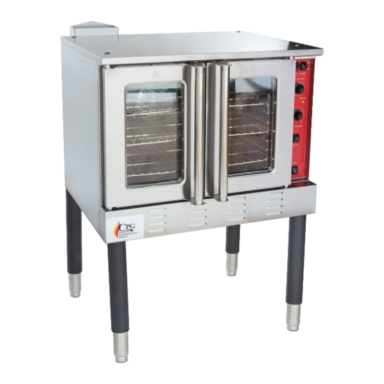
USER MANUAL PRODUCT OVERVIEW The 351FEC100 features a sturdy steel construction with 4 adjustable legs. It is equipped with a built-in two speed convection fan for temperature uniformity throughout the cavity. Three high efficiency heating tubes and an electronic thermostat ensure accurate temperature for precise cooking. The 351FEC200 features two ovens cavities helping you meet higher production demands. - Page 4 USER MANUAL DOUBLE DECK OVEN www.CookingPerformanceGroup.com...
-
Page 5: Oven Stacking Instructions
USER MANUAL STACKING OVEN INSTRUCTIONS *Requires two ovens and stacking kit NOTE We recommend that the stacking is performed by an authorized service agent or installer. www.CookingPerformanceGroup.com... - Page 6 USER MANUAL BOTTOM OVEN STEP 1 Install the fixer kit. Install the casters or legs. www.CookingPerformanceGroup.com...
- Page 7 USER MANUAL STEP 2 Align the top knobs with the notches on the bottom of the oven. www.CookingPerformanceGroup.com...
- Page 8 USER MANUAL STEP 3 Attach the top and bottom unit with connecting plates and screws. www.CookingPerformanceGroup.com...
- Page 9 USER MANUAL STEP 4 Stacking complete www.CookingPerformanceGroup.com...
-
Page 10: Specifications
29” × 20” × 22¼” 29” × 20” × 22¼” per chamber Temperature Range (˚F) 150- 550˚F 150- 550˚F FAN-60HZ MODEL TOTAL POWER (kW) VOLTAGE PHASES HIGH SPEED LOW SPEED 351FEC100B 1725 351FEC100D 10.1-11.9 220-240 1725 351FEC100C 1725 351FEC100E 10.1-11.9 220-240 1725 Each oven requires its own electrical connection. -
Page 11: Startup
USER MANUAL STARTUP INSTALLATION: Remove packaging before beginning installation. Note: Some parts are protected with an adhesive film. Remove any glue residue with approved substances, such as petrol; never use abrasive substances. Mount the feet, adjusting them to make the unit level. The connections to the electric network must be close to the equipment and easy to reach. - Page 12 USER MANUAL ELECTRIC CONNECTION: The oven must be electrically grounded in accordance with all local and national codes (In the USA the National Electrical code ANSI/NFPA no. 70 is applicable). WARNINGS: Always ensure proper supervision while the equipment is in use. Simple adjustments to knobs, leg height, etc.
-
Page 13: Working Instructions & Operation
USER MANUAL WORKING INSTRUCTIONS & OPERATIONAL FLOW Fan Mode: CONTROLS: In COOK mode, the fan runs continuously except when the doors are open. The fan does not cycle with the operation of the heating element. In COOL mode, the fan runs continuously even Power Switch: if the doors are open. - Page 14 USER MANUAL TO COOK, DO THE FOLLOWING: Turn the oven ON using the Power Switch at the top of the control panel. Select the desired fan speed using the Fan Speed switch. The appropriate fan speed (HI or LOW) depends on the type of food being cooked.
-
Page 15: Cleaning & Maintenance
USER MANUAL CLEANING & MAINTENANCE Before cleaning, turn off the unit and let it cool down. Carefully clean the equipment daily to promote proper operation and long life. Steel surfaces must be cleaned with dish detergent diluted in very hot water using a soft cloth; do not use abrasive powder detergents or corrosive substances. -
Page 16: Electrical Diagram
USER MANUAL ELECTRICAL DIAGRAMS 1 PHASE: www.CookingPerformanceGroup.com... - Page 17 USER MANUAL 3 PHASE: www.CookingPerformanceGroup.com...
-
Page 18: Parts Diagrams & Parts Lists
USER MANUAL PARTS DIAGRAM WHOLE ASSEMBLY: www.CookingPerformanceGroup.com... - Page 19 USER MANUAL PARTS DIAGRAM PART CODE OUR ITEM # DESCRIPTION 20217046028 35117046028 LOWER FRONT COVER PLATE 2(A) 20165002011 35165002011 RIGHT DOOR ASSEMBLY 3 (A) 20165002014 35165002014 LEFT DOOR ASSEMBLY 302201928 351201928 DOOR SHAFT BUSHING 302110577 351110577 OVEN RACK GUIDE 20217046026 35117046026 LEFT SIDE PANEL 7 (B)
- Page 20 USER MANUAL PARTS DIAGRAM CONTINUED PART CODE OUR ITEM # DESCRIPTION 302090152 351090152 LEG ASSEMBLY 301080079 351080079 DOOR TRAVEL SWITCH 302090088 351090088 ADJUSTABLE FOOT 34 (E) 20165002008 35165002008 CONTROL PANEL ASSEMBLY 20217046018 35117046018 CONTROL PANEL 302190015 351190015 DOOR HINGE 301080141 351080141 WATER-PROOF SWITCH 301030169...
- Page 21 USER MANUAL PARTS DIAGRAM RIGHT AND LEFT DOORS (2A, 3A): www.CookingPerformanceGroup.com...
- Page 22 USER MANUAL PARTS DIAGRAM CONTINUED PART CODE OUR ITEM # DESCRIPTION 20165002016 35165002016 DOOR STOP ASSEMBLY 2- i 20265002092 35165002092 LEFT DOOR HANDLE FIXING PLATE(STRAIGHT) 2- ii 20265002093 35165002093 RIGHT DOOR HANDLE FIXING PLATE(STRAIGHT) 20265002055 35165002055 DOOR HANDLE(ROUND TUBE) 20265002046 35165002046 EXTERIOR PLATE OF RIGHT DOOR 20165002012...
- Page 23 USER MANUAL PARTS DIAGRAM COVER ASSEMBLY (7B) www.CookingPerformanceGroup.com...
- Page 24 USER MANUAL PARTS DIAGRAM CONTINUED PART CODE OUR ITEM # DESCRIPTION 20265002037 35165002037 PERIMETER DOOR GASKET RIGHT 20265002036 35165002036 PERIMETER DOOR GASKET 20265002035 35165002035 BOTTOM 20117046004 35117046004 PERIMETER DOOR GASKET TOP 20265002038 35165002038 FRONT FRAME ASSEMBLY 20265002039 35165002039 PERIMETER DOOR GASKET LEFT 20117046003 35117046003 OVEN RACK GUIDE CLIP...
- Page 25 USER MANUAL PARTS DIAGRAM MOTOR (15C) www.CookingPerformanceGroup.com...
- Page 26 USER MANUAL PARTS DIAGRAM CONTINUED PART CODE OUR ITEM # DESCRIPTION 301010212 351010212 TURBO FAN 20265002066 35165002066 MOTOR THERMAL BAFFLE PLATE 1 302212429 351212429 M6*20 SCREW 20217046022 35117046022 MOTOR INSTALLATION STRENGTHENING PLATE 302212449 351212449 M8*20 SCREW 20217046021 35117046021 MOTOR THERMAL BAFFLE PLATE 2 20217046023 35117046023 MOTOR COTTON BUSHING...
- Page 27 USER MANUAL PARTS DIAGRAM CONTROL PANEL (34E) www.CookingPerformanceGroup.com...
- Page 28 USER MANUAL PARTS DIAGRAM CONTINUED PART CODE OUR ITEM # DESCRIPTION 302190015 351190015 DOOR HINGE 301080141 351080141 WATER-PROOF SWITCH 301130141 351130141 POWER INDICATOR 301130140 351130140 WORKING INDICATOR 301030169 351030169 THERMOSTAT 301120028 351120028 TIMER 301100086 351100086 BUZZER 20265002041 35165002041 SIDE PLATE OF CONTROL PANEL 20217046018 3511704608 CONTROL PANEL...
- Page 29 USER MANUAL PARTS DIAGRAM RIGHT SIDE www.CookingPerformanceGroup.com...
- Page 30 USER MANUAL PARTS DIAGRAM CONTINUED PART CODE OUR ITEM # DESCRIPTION 20217046031 35117046031 WATER BAFFLE 20217046036 35117046036 SMALL FAN FIXED PLATE 20265002032 35165002032 COTTON COVER PLATE 20217046016 35117046016 RIGHT COTTON COVER PLATE 301071088 351071088 TERMINALS ASSEMBLY 301010246 351010246 COOL FAN 20217046030 35117046030 COMPONENT FIXED PLATE...
Need help?
Do you have a question about the 351FEC100B and is the answer not in the manual?
Questions and answers