Table of Contents
Advertisement
Quick Links
Advertisement
Table of Contents

Subscribe to Our Youtube Channel
Summary of Contents for YANYU ITX-K100
- Page 1 Intel○ R Bay Trail Processor ITX-K100 VER:2.3 - 1 -...
- Page 2 Before ordering the products, please learn about the product performance from the distributors to see if it is in line with your needs. YANYU GONGKONG is a registered trademark of Shenzhen Hanzsung Technology CO.,LTD. The ownership of other trademarks involved in this manual is owned by its respective owners.
- Page 3 ITX-K100 Base on Intel® Bay Trail platform Mini-ITX motherboard Safety Instructions 1.Please read this manual carefully before using this product. 2.Please put all unused/uninstalled boards and cards in anti-static bags. 3.Please first place your hands on grounding metal object for a while before you go to take out the board from its package, so as to release body electrostatic.
- Page 4 ITX-K100 Base on Intel® Bay Trail platform Mini-ITX motherboard Order Information Model Processor Frequency Memory HDMI LVDS Power ITX-K100_2 J1900 2.0G/4C 1*SODDR3 2*24BIT 2*8111F DC12V L VER:2.3 ITX-K100_D J1900 2.0G/4C 1*SODDR3 2*24BIT 1*8111F DC12V 6L VER:2.3 ITX-K100 J1900 2.0G/4C 1*SODDR3...
-
Page 5: Table Of Contents
ITX-K100 Base on Intel® Bay Trail platform Mini-ITX motherboard Catalog Catalog ..........................- 4 - Chapter 1 Product Introduction .................... - 6 - 1.1 Product Introduction ....................- 6 - 1.2 Product Specification ....................- 6 - Chapter 2 Hardware Installation Instructions ..............- 11 - 2.1 Motherboard Dimension.................. - Page 6 ITX-K100 Base on Intel® Bay Trail platform Mini-ITX motherboard 3.2.3 Advance Settings ....................- 36 - 3.2.4 ACPI Settings ....................- 37 - 3.2.5 Super IO Configuration ..................- 38 - 3.2.6 PC Health Status ....................- 40 - 3.2.7 CPU Configuration ..................... - 41 - 3.2.8 System Power Management ................
-
Page 7: Chapter 1 Product Introduction
1.1 P RODUCT NTRODUCTION ITX-K100 used fanless cooling design, No noise, can avoid the problem of dust accumulation fan, This industrial motherboard is very suitable for harsh industrial environment, Onboard Intel® Celeron J1900/4Cores/2.0GHz or J1800/2Cores / 2.41GHz Processor,It’s has strong graphics processing ability and application computing power, support single channel DDR3L 1333/1066Mhz Memory, up to 8GB,Integrated Intel®... - Page 8 ITX-K100 Base on Intel® Bay Trail platform Mini-ITX motherboard 1*HDMI ,the highest resolution as 1920X1080@60HZ 1*LVDS support dual channel 24bit,support single display, double display mode, double extension. (LVDS screen voltage support 12V output, default is 3.3V. Before using LVDS, please understand the requirements of the rated voltage after setting, so as not to burn the screen.
- Page 9 ITX-K100 Base on Intel® Bay Trail platform Mini-ITX motherboard 1* Line out (Green)、1* MIC (Red) 1* 12V DC power input connector Internal I/O 1* 4pin ATX power port(can do 12V power input/output port) 1* 2pin 12V DC power port 4* USB 2.0 2*5Pin 1* USB 2.0 1*5Pin...
- Page 10 ITX-K100 Base on Intel® Bay Trail platform Mini-ITX motherboard Watchdog Support hardware reset function(L256,0-255seconds) Power Adopt DC 12V power supply Dimensions, Environment Dimension :170mm x 170mm Operating Temp:-10℃~60℃ Operating Humidity:5~90%(Relative humidity, Non-condensing) Storage Temp:-20℃~70℃ - 9 -...
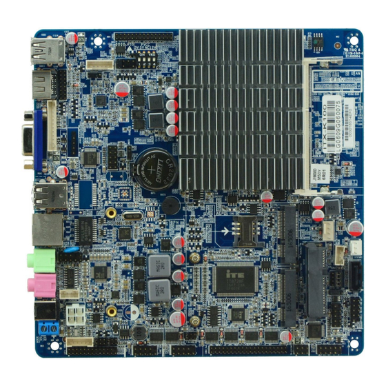
- Page 11 ITX-K100 Base on Intel® Bay Trail platform Mini-ITX motherboard Photo as below ITX-K100 front view ITX-K100 I/O front view - 10 -...
-
Page 12: Chapter 2 Hardware Installation Instructions
2.1 M OTHERBOARD IMENSION Following picture is the front interfaces and dimension of board ITX-K100 Please pay attention to the installation process. Improper installation of some components may lead to system failure. Note: When installing the board, please wear anti-static gloves in case of any electrostatic damage caused during the installation. -
Page 13: Interfaces Location
ITX-K100 Base on Intel® Bay Trail platform Mini-ITX motherboard Tips: 1. Please select suitable screw and adopt right installation method, otherwise, motherboard will be damaged. 2. How to identify the 1st pin of jumpers and connectors : Observe letter beside the socket : It would be marked with "1"... -
Page 14: Installation Steps
ITX-K100 Base on Intel® Bay Trail platform Mini-ITX motherboard Tips: How to identify the alarms: (Long beep indicates system memory error; Short beep indicates the computer is power on). LVDS screen working voltage support 3.3V、5V、12V voltage output, default is 3.3V, before using LVDS, please understand the requirements of the working voltage and then set. -
Page 15: Jumper Function Settings
ITX-K100 Base on Intel® Bay Trail platform Mini-ITX motherboard 2.5 J UMPER UNCTION ETTINGS Please refer to following instructions to do jumper settings before installing the motherboard. How to identify the 1st pin of all jumpers and interfaces, Please observe the Remark: word mark on the side of the plug socket, which will be a "1"... -
Page 16: Jpw1Jumper Settings
ITX-K100 Base on Intel® Bay Trail platform Mini-ITX motherboard JBAT1 SATA1_SW1 JPW1 JBAT1 jumper settings: Settings JBAT1 Normal Status, system default setting Clear the CMOS content, all the BIOS settings are returned to the factory Do not clear CMOS when the computer is power on, otherwise, it will cause damage to the motherboard ! 2.5.2 JPW1... -
Page 17: Interfaces Description
ITX-K100 Base on Intel® Bay Trail platform Mini-ITX motherboard Shorted 2-3\5-6\8-9\11-12 at the same time shorted connector to the default SATA5 hard disk interface 2.6 I NTERFACES ESCRIPTION Please read the following instructions carefully before you connecting the external connectors in case of any damage caused to the motherboard ! (SATA2、SATA5、PWROUT1)... -
Page 18: Serial Port(Com1、Com2、Com3-6、Jp15、Jp16、Tx-Rxcom3)
ITX-K100 Base on Intel® Bay Trail platform Mini-ITX motherboard SATA_RXN SATA_RXP SATA5 definition: Signal Name Signal Name SATA_TXP1 SATA_TXN1 SATA_RXN1 SATA_RXP1 3.3V 3.3V 3.3V 5V-HDD 5V-HDD 5V-HDD 12V-HDD 12V-HDD 12V-HDD Tips:1、PWROUT1 hard disk power supply connector pin 1 is 12V output, pin 4 is + 5V output, please use our standard power line, In order to avoid burning the hard disk. - Page 19 ITX-K100 Base on Intel® Bay Trail platform Mini-ITX motherboard JP16 COM2 COM1 JP15 COM3-6 TX-RXCOM3 COM1、COM2 Definition: Signal Name Signal Name COM3-6 definition: Signal Name Signal Name COM3_DCD COM3_RXD COM3_TXD COM3_DTR COM3_DSR COM3_RTS COM3_CTS COM3-RI COM4_DCD COM4_RXD - 18 -...
- Page 20 ITX-K100 Base on Intel® Bay Trail platform Mini-ITX motherboard COM4_TXD COM4_DTR COM4_DSR COM4_RTS COM4_CTS COM4-RI COM5_DCD COM5_RXD COM5_TXD COM5_DTR COM5_DSR COM5_RTS COM5_CTS COM5-RI COM6_DCD COM6_RXD COM6_TXD COM6_DTR COM6_DSR COM6_RTS COM6_CTS COM6-RI JP16 Setting: settings function(JP16) 1-2 shorted RS232 COM1 3-4shorted...
-
Page 21: Parallel Port(Lpt1
ITX-K100 Base on Intel® Bay Trail platform Mini-ITX motherboard (LPT1) 2.6.3 P ARALLEL PORT Board provide 1* LPT port, 2*13pin LPT1 LPT1 Definition: Singal Name Singal Name STB- AFD- ERR- INIT- SLIN- ACK- BUSY SLCT - 20 -... -
Page 22: Display Ports
ITX-K100 Base on Intel® Bay Trail platform Mini-ITX motherboard 2.6.4 D ISPLAY PORTS (VGA、JVGA1、HDMI1、J_HDMI1、LVDS1、INVERTER1、JP9、JP10、SW1) Motherboard Provide1* standard VGA, 1* 1X12pin JVGA1, 1* standard HDMI, 1* 2X 8pin JHDMI1 1* LVDS Note: VGA1 and JVGA1 is the same signal, HDMI1 and JHDMI1 is the same... - Page 23 ITX-K100 Base on Intel® Bay Trail platform Mini-ITX motherboard DDCCLK JVGA1 definition: Signal Name Signal Name VSYNC HSYNC DDC_SDA DDC_SCL HDMI1 definition Signal Name Signal Name TMDS Data2+ TMDS Data2 Shield TMDS Data2- TMDS Data1+ TMDS Data1 Shield TMDS Data1-...
- Page 24 ITX-K100 Base on Intel® Bay Trail platform Mini-ITX motherboard LVDS1 definition: Signal Name Signal Name LCDVDD LCDVDD LCDVDD LVDS_A0- LVDS_A0+ LVDS_A1- LVDS_A1+ LVDS_A2- LVDS_A2+ LVDSA_CLK- LVDSA_CLK+ LVDS_A3- LVDS_A3+ LVDS_B0- LVDS_B0+ LVDS_B1- LVDS_B1+ LVDS_B2- LVDS_B2+ LVDSB_CLK- LVDSB_CLK+ LVDS_B3- LVDS_B3+ Different LCD screen voltage may be different, Motherboard provide 3.3V,5V,12V...
- Page 25 ITX-K100 Base on Intel® Bay Trail platform Mini-ITX motherboard Settings JP10 1-2 shorted 3.3V 3-4 shorted 5-6 shorted 7-8 shorted SW1 used to set the resolution of LVDS, Detailed settings as follows: SW1 switch as below: 1、2、3、4 deputy 1,5、6、7、8 deputy 0.
-
Page 26: Power Ports(Dc12V_In2、Atx_12V1、Dc2)
ITX-K100 Base on Intel® Bay Trail platform Mini-ITX motherboard 2.6.5 P (DC12V_IN2、ATX_12V1、DC2) OWER PORTS Board provide 1* 4pin ATX power interface, support 12V input/output 1* DC12_IN2 can support 12V input/output 1* 2pin blue power element DC2 can support 12V input/out... -
Page 27: Audio (Jphone1、Jmick1、Fp_Audio1、Jspkr1)
ITX-K100 Base on Intel® Bay Trail platform Mini-ITX motherboard DC12_IN2 ATX_12V1 ATX_12V1 definition: Signal Name DC2 definition: Signal Name 2.6.6 A (JPHONE1、JMICK1、FP_AUDIO1、JSPKR1) UDIO Motherboard provide 1* JPHONE1、1* JMICK1 are the standard audio jack, 1* 2X5pin Front panel audio connector, 1* 4pin amplifier interface. -
Page 28: Kb/Ms Port(Kbms1)
ITX-K100 Base on Intel® Bay Trail platform Mini-ITX motherboard JPHONE1 FP_AUDO1 JSPKR1 JMICK1 FP_AUDIO1 definition: Signal Name Signal Name MIC-L MIC-R Line out-R Sense-FB Line OUT-L JSPKR1(Amplifier)definition: Signal Name SPKR+ SPKR- SPKL- SPKL+ 2.6.7 KB/MS P (KBMS1) Board provide1*1X6pin KB/MS port Note: When using, need to use switching lines into the definition of the PS/2 KB/MS connector. -
Page 29: Usb (Usb1、Usb2、Usb3、Usb4、Jusb5)
ITX-K100 Base on Intel® Bay Trail platform Mini-ITX motherboard KBMS1 KBMS1 definition: Signal Name VCC(standby) KB_DT KB_CK MS_DT MS_CK 2.6.8 USB (USB1、USB2、USB3、USB4、JUSB5) Provide 3* standard USB2.0 (USB1 and LAN2 two choose one) ;1* standard USB3.0;2* 2×5Pin USB2.0 and 1*1X5Pin USB2.0 (Pitch:2.54mm)... -
Page 30: Lan And Fan Port(Lan1、Cpufan1、Sysfan1)
ITX-K100 Base on Intel® Bay Trail platform Mini-ITX motherboard USB3 JUSB5 USB1 USB4 USB2、USB4 definition: USB2 Signal Name Signal Name JUSB5 definition: Signal Name 2.6.9 LAN (LAN1、CPUFAN1、SYSFAN1) PORT Board provide 1* standard LAN,(USB1 and LAN2 two choose one) 。 1* 4pin CPU fan connector,1* 3pin system fan connector。... -
Page 31: Front Panel Interface(Fpanel1、Power)
ITX-K100 Base on Intel® Bay Trail platform Mini-ITX motherboard LAN1 CPUFAN1 SYSFAN1 SYSFAN1 definition: Signal Name +12V CPUFAN1 definition: Signal Name +12V Note:DET:Fan speed pulse output;PWM:Fan speed PWM control 2.6.10 F (FPANEL1、POWER) RONT PANEL INTERFACE The front panel pin is used to connect the function button and indicator lights on the... - Page 32 ITX-K100 Base on Intel® Bay Trail platform Mini-ITX motherboard front panel of chassis. In total 1* 2x 5 Pin. 。 FPANEL1 FPANEL1definition: Signal Name Signal Name HDDLED+ PWRLED+ HDDLED- PWRLED- PWRBTN# RESETBTN# (1)Hard Disk Indicator (The 1 HDD LED is LED Positive electrode )When Hard disk is in the operation of read and write ,The indicator light will flashes, Means the hard drive is running.
- Page 33 ITX-K100 Base on Intel® Bay Trail platform Mini-ITX motherboard with the System that made it cant continue to work, Reset and it can make the system work again. (4) Power switch control(the 6th,8th POWER BUTTON)The two pin connected to the bounce switch on the front panel of the chassis ,and then it can be used to connect or cut off the power.
-
Page 34: Mini-Pcie (Mini-Pcie1、Msata1)
ITX-K100 Base on Intel® Bay Trail platform Mini-ITX motherboard GPIO1 definition: Function Default Remarks Input High Output Set up by BIOS Input High Output Set up by BIOS Input High Output Set up by BIOS Input High Output Set up by BIOS 2.6.12 M... -
Page 35: Bios Description
ITX-K100 Base on Intel® Bay Trail platform Mini-ITX motherboard ddChapter 3 BIOS Settingdd 3.1. BIOS DESCRIPTION BIOS(Basic Input an Output System)Through the CMOS chip on the motherboard, a record of the hardware equipment of the system parameter setting. BIOS contains... -
Page 36: Main Menu(Bios Information And Time/Date
ITX-K100 Base on Intel® Bay Trail platform Mini-ITX motherboard Press<Enter>,you can enter the option of the child. 4、Use the arrow keys and the <Enter> key to modify the value of the selected items, press the Enter key to select the BIOS option and modify it. -
Page 37: Advance Settings
ITX-K100 Base on Intel® Bay Trail platform Mini-ITX motherboard Set the current date, In the form of month / day / year. The setting range is: Month(Jan.-Dec.),Date(01-31),Year(Max to 2099),Week(Mon.~Sun.)。 System Time : Set the current time, In the form of time/minute/second, The setting range is: Hour(00-23),Minute(00-59),Second(00-59)。... -
Page 38: Acpi Settings
ITX-K100 Base on Intel® Bay Trail platform Mini-ITX motherboard 3.2.4 ACPI S ETTINGS Enable ACPI Auto Configuration : This item is automatically configured for the ACPI, Allow (Enabled) or close (Disabled) BIOS ACPI automatic configuration ,default is close(disabled) Enable Hibernation :Enabled or Disabled system sleep function(OS/S4 sleep state)... -
Page 39: Super Io Configuration
ITX-K100 Base on Intel® Bay Trail platform Mini-ITX motherboard 3.2.5 S IO C UPER ONFIGURATION Serial Port 1 Configuration:This is the serial port 1 settings option, IO Super configuration information, including the COM port interrupt number and address settings. Serial Port 2 Configuration:This is the serial port 2 settings option, IO Super configuration information, including the COM port interrupt number and address settings. - Page 40 ITX-K100 Base on Intel® Bay Trail platform Mini-ITX motherboard Watch dog AND GPIO Controller Configuration Watch dog Controller: Watch dog settings , [Disabled] or [Second mode] the watchdog is set to the second mode ,[Minute Mode],the watchdog is set to the minute mode.
-
Page 41: Pc Health Status
ITX-K100 Base on Intel® Bay Trail platform Mini-ITX motherboard 3.2.6 PC H EALTH TATUS Hardware security detection, display the current system temperature, CPU temperature, fan speed, and other relevant voltage value. The above parameters have a certain range, the system can not exceed the scope of the operation. -
Page 42: Cpu Configuration
ITX-K100 Base on Intel® Bay Trail platform Mini-ITX motherboard 3.2.7 CPU C ONFIGURATION Read only items contain details of the CPU, including the CPU manufacturers, models, frequency, the size of the first level cache size, the size of the two cache and other information. -
Page 43: System Power Management
ITX-K100 Base on Intel® Bay Trail platform Mini-ITX motherboard Hyper-Threading : Set whether to use the CPU hyper threading technology, set the value of [Enabled][Disabled]. Intel Virtualization Technology : Intel Virtualization Technology Is Intel's CPU in the system of virtual technology. It... - Page 44 ITX-K100 Base on Intel® Bay Trail platform Mini-ITX motherboard Restore on AC Power loss:Restore on AC Power loss:This option is used to set up the Power on (Restore on AC Power loss), choose Power off means need to press the power button to boot when power on, choose Power on means it’s direct boot...
-
Page 45: Sata Configuration
ITX-K100 Base on Intel® Bay Trail platform Mini-ITX motherboard 3.2.9 SATA C ONFIGURATION Serial-ATA (SATA) :enabled or disabled。 SATA Speed Support :Serial interface support speed. SATA ODD Port :Configure serial remote transmission ports. SATA Mode: AHCI or IDE. Serial-ATA Port 0: enabled or disabled。... -
Page 46: Usb Configuration
ITX-K100 Base on Intel® Bay Trail platform Mini-ITX motherboard 3.2.10 USB C ONFIGURATION Legacy USB Support : The old version of the USB settings, if you need to support USB devices in DOS, such as U disk, USB keyboard, etc., will be set to [Enabled] or [Auto]. on the contrary, the choice of [Disabled]. -
Page 47: Chipset Settings
ITX-K100 Base on Intel® Bay Trail platform Mini-ITX motherboard 3.2.11 C HIPSET SETTINGS IGFX Boot Display :Vbios option, the graphics boot configuration - 46 -... - Page 48 ITX-K100 Base on Intel® Bay Trail platform Mini-ITX motherboard Integrated Graphics Device: enable integrated graphics devices or not Primary Display :configuration first display. PAVC: HD video playback mode, using mode G45 can start the LITE chipset hardware acceleration decoding function.
- Page 49 ITX-K100 Base on Intel® Bay Trail platform Mini-ITX motherboard PCH-IO Configuration : Bridge configuration options including sound card, network card, call self start options System Agent (SA) Configuration : North Bridge configuration options,including memory, display equipment, LVDS and other options.
- Page 50 ITX-K100 Base on Intel® Bay Trail platform Mini-ITX motherboard XHCI Mode: Set XHCI Mode USB to open or NOT . USB OTG Support: Set OTG USB device support function, options have Disabled(default), Enabled USB VBUS: Open USB bus USB Per-Port Control :...
-
Page 51: Boot
ITX-K100 Base on Intel® Bay Trail platform Mini-ITX motherboard 3.2.12 B Setup Prompt Timeout:Set the prompt timeout, press the Setup shortcut key to wait time. If you have not press the Setup shortcut key in the setup time it will continue to start. -
Page 52: Security
ITX-K100 Base on Intel® Bay Trail platform Mini-ITX motherboard 3.2.13 S ECURITY Password character length hint: the minimum length is 3, the maximum length is 20 Administrator Password : The option is used to set the super user password User Password :... -
Page 53: Save&Exit
ITX-K100 Base on Intel® Bay Trail platform Mini-ITX motherboard 3.2.14 S & E Save Changes and Exit :Save the BIOS settings, and exit the settings interface, continue to start the computer Discard Changes and Reset : Discard changes and exit setup interface, restart the computer. -
Page 54: Appendix
ITX-K100 Base on Intel® Bay Trail platform Mini-ITX motherboard Appendix :G PPENDIX ONE LOSSARY OF TERMS ACPI Advanced configuration and power management.The ACPI specification allows the operating system to control most of the power of the computer and its additional equipment. - Page 55 ITX-K100 Base on Intel® Bay Trail platform Mini-ITX motherboard Serial port, a universal serial communication interface, generally use the standard DB9 common interface connection mode. DIMM Dual in-line memory module. A memory chip group of small circuit board. The memory bus width of 64bit.
- Page 56 ITX-K100 Base on Intel® Bay Trail platform Mini-ITX motherboard achieve this feature, BIOS support PnP and a PnP expansion cards are required. POST During the start up system, BIOS will perform a continuous testing on the system, including the detection of RAM, keyboard, hard drives, etc., to see whether they are properly connected and whether the normal work.
-
Page 57: Appendix Two:common Trouble Analysis And Solution
ITX-K100 Base on Intel® Bay Trail platform Mini-ITX motherboard :C PPENDIX OMMON TROUBLE ANALYSIS AND SOLUTION Common faults Checkpoint 1.Make sure the power cable is connected properly 2. Please confirm whether the power supply to meet the requirements of the motherboard After the power on 3. - Page 58 ITX-K100 Base on Intel® Bay Trail platform Mini-ITX motherboard 2. Please confirm whether the system is too small to partition the remaining space 3. Please confirm whether the CPU cooling fan is normally rotating 1. Please confirm whether the CPU cooling fan is normally rotating 2.
Need help?
Do you have a question about the ITX-K100 and is the answer not in the manual?
Questions and answers