Table of Contents
Advertisement
S
ABOTAGE
DEFAULT INSTALLER CODE
000000
(To modify the installer code, refer to section [1000], "Installer Code Programming" on page 22)
DEFAULT SYSTEM MASTER CODE
1234
123456
or
HOW DO I ENTER PROGRAMMING MODE?
STEP 1: Press and hold the [0] key
STEP 2: Enter your [
INSTA LLER COD E
STEP 3: Enter 4-digit [
SE CTION
STEP 4: Enter required [
]
DA TA
DECIMAL AND HEXADECIMAL PROGRAMMING TABLE
Key
[0] to [9]
0 to 9 (Hexa & Decimal)
[
]
A (Hexa Only)
STAY
[
]
B (Hexa Only)
FORC E
[
]
C (Hexa Only)
AR M
[
]
D (Hexa Only)
D ISA RM
-P
H
ROOF
P
ROGRAMMING
Software Version V1.3
]
]
Value or Action
-S
IGH
ECURITY
G
Key
[
]
E (Hexa Only)
B YP
[
]
F (Hexa Only)
MEM
[
]
Exit section without saving (Hexa & Decimal)
C LEAR
[
]
Save current data and advance to next section (Hexa Only)
EN TER
www.paradox.ca
S
(DGP-NE96)
YSTEM
UIDE
DGP-NE96
Value or Action
Advertisement
Table of Contents

Related Manuals for Paradox Digiplex NE DGP-NE96


Summary of Contents for Paradox Digiplex NE DGP-NE96
- Page 1 F (Hexa Only) STAY B (Hexa Only) Exit section without saving (Hexa & Decimal) FORC E C LEAR C (Hexa Only) Save current data and advance to next section (Hexa Only) AR M EN TER D (Hexa Only) D ISA RM www.paradox.ca...
- Page 2 © 2002 Paradox Security Systems. Specifications may change without prior notice. DigiplexNE and WinLoad are a trademark of Paradox Security Systems. Warning: This equipment must be installed and maintained by qualified ser vice personnel only. DigiplexNE DGP-NE96 - 2 -...
-
Page 3: Table Of Contents
Table of Contents Serial Number List..........................4 Zone Programming ..........................7 Zone Report Codes ..........................10 Zone Labels ............................11 Keyswitch Programming ........................13 Programmable Outputs ........................15 User Code Options ..........................23 Arming and Disarming Report Codes ....................24 Access Control Sections ........................ -
Page 4: Serial Number List
Serial Number List All modules connected to the control panel’s communication bus have an 8-digit serial number. Remove the extra serial number sticker from each module’s PC board and affix in the appropriate spaces provided below (maximum 127 modules). Module Type & Details Serial # Module Type &... - Page 5 Module Type & Details Serial # Module Type & Details Serial # 45:_____________________________________ _________________ 69:_____________________________________ _________________ 46:_____________________________________ _________________ 70:_____________________________________ _________________ 47:_____________________________________ _________________ 71:_____________________________________ _________________ 48:_____________________________________ _________________ 72:_____________________________________ _________________ 49:_____________________________________ _________________ 73:_____________________________________ _________________ 50:_____________________________________ _________________ 74:_____________________________________ _________________ 51:_____________________________________ _________________ 75:_____________________________________ _________________ 52:_____________________________________ _________________ 76:_____________________________________...
- Page 6 Module Type & Details Serial # Module Type & Details Serial # 93:_____________________________________ _________________ 111:_____________________________________ _________________ 94:_____________________________________ _________________ 112:_____________________________________ _________________ 95:_____________________________________ _________________ 113:____________________________________ _________________ 96:_____________________________________ _________________ 114:____________________________________ _________________ 97:_____________________________________ _________________ 115:____________________________________ _________________ 98:_____________________________________ _________________ 116:____________________________________ _________________ 99:_____________________________________ _________________ 117:____________________________________ _________________ 100:_____________________________________ _________________ 118:____________________________________ _________________...
-
Page 7: Zone Programming
DigiplexNE DGP-NE96 - 7 - Programming Guide... - Page 8 DigiplexNE DGP-NE96 - 8 - Programming Guide...
- Page 9 DigiplexNE DGP-NE96 - 9 - Programming Guide...
-
Page 10: Zone Report Codes
DigiplexNE DGP-NE96 - 10 - Programming Guide... -
Page 11: Zone Labels
DigiplexNE DGP-NE96 - 11 - Programming Guide... - Page 12 DigiplexNE DGP-NE96 - 12 - Programming Guide...
-
Page 13: Keyswitch Programming
DigiplexNE DGP-NE96 - 13 - Programming Guide... - Page 14 DigiplexNE DGP-NE96 - 14 - Programming Guide...
-
Page 15: Programmable Outputs
Programmable Outputs PGM TEST MODE Section Description [0901] Test PGM1: Activates PGM1 for 8 seconds to verify if the PGM is functioning correctly. [0902] Test PGM2: Activates PGM2 for 8 seconds to verify if the PGM is functioning correctly. [0903] Test PGM3: Activates PGM3 for 8 seconds to verify if the PGM is functioning correctly. - Page 16 Event Group Event Feature Group Feature Start # End # PC Fail to communicate Midnight NEware/WinLoad User Login NEware/WinLoad User Logout Non-reportable Event (con’t) User Initiated Callup Force Answer Force Hangup Any Non-reportable Event Not Used Not Used User Codes 000 to 255 000 to 255 000 to 255 User Codes 256 to 511...
- Page 17 Event Group Event Feature Group Feature Start # End # User Codes 001 to 255 001 to 255 001 to 255 User Codes 256 to 511 000 to 255 000 to 255 Disarm after alarm with Master User Codes 512 to 767 000 to 255 000 to 255 User Codes 768 to 999...
- Page 18 Event Group Event Feature Group Feature Start # End # User Codes 768 to 999 000 to 231 000 to 231 Duress Alarm by User (con’t) Any User Code Not Used Not Used Zone Shutdown 001 to 096 001 to 096 Zone Tamper Zone Numbers 001 to 096...
- Page 19 Event Group Event Feature Group Feature Start # End # User Codes 001 to 255 001 to 255 001 to 255 User Codes 256 to 511 000 to 255 000 to 255 Early to Arm by User User Codes 512 to 767 000 to 255 000 to 255 User Codes 768 to 999...
- Page 20 Event Group Event Feature Group Feature Start # End # User Codes 001 to 255 001 to 255 001 to 255 User Codes 256 to 511 000 to 255 000 to 255 Access Denied to User User Codes 512 to 767 000 to 255 000 to 255 User Codes 768 to 999...
- Page 21 Event Group Event Feature Group Feature Start # End # Special Status Fail to Communicate 1 Fail to Communicate 2 Fail to Communicate 3 Fail to Communicate 4 Fail to Communicate with PC Future Use Future Use Module Tamper Trouble Module ROM error Module TLM error Module Failure to Communicate...
- Page 22 INPUT SPEEDS Section Data - Decim al Value (001 - 255) Description Default [0961] __/__/__ (001 to 255) x 30 msec. 600 msec. N PUT PEE D OF N PUT [0962] __/__/__ (001 to 255) x 30 msec. 600 msec. N PUT PEE D OF N PUT...
-
Page 23: User Code Options
The instructions that follow detail how to program access codes when using an LCD keypad. For instructions on how to program users when using a Grafica keypad, refer to Grafica’s Online Manual, which can be downloaded for free from our Web site (www.paradox.ca). Program User Code Options, Partition Assignment and Access Control features for user 001 to 999. -
Page 24: Arming And Disarming Report Codes
Arming and Disarming Report Codes Ademco slow, Silent Knight fast, SESCOA, Ademco express or Pager formats: Key-in desired 2-digit hexa values from 00 to FF. Ademco format: Use section [4033] to program a set of default Ademco report codes from the “Automatic Report Code Programming” on page 41. Then to program the remaining report codes or to change some of the defaults, enter the individual sections and key-in the desired 2-digit hexa value found in the “Contact ID Report Code List”... -
Page 25: Access Control Sections
[2126] __/__ Access Code 26 [2145] __/__ Access Code 45 [2164] __/__ Access Code 64 [2183] __/__ Access Code 83 [2127] __/__ Access Code 27 [2146] __/__ Access Code 46 [2165] __/__ Access Code 65 [2184] __/__ Access Code 84 [2128] __/__ Access Code 28 [2147]... - Page 26 Door 19 [2219] __/__/__/__/__/__/__/__ [2269] 1 2 3 4 5 * * * [2319] __/__/__/__/__/__/__/__/__/__/__/__/__/__/__/__ Door 20 [2220] __/__/__/__/__/__/__/__ [2270] 1 2 3 4 5 * * * [2320] __/__/__/__/__/__/__/__/__/__/__/__/__/__/__/__ Door 21 [2221] __/__/__/__/__/__/__/__ [2271] 1 2 3 4 5 * * * [2321] __/__/__/__/__/__/__/__/__/__/__/__/__/__/__/__ Door 22...
- Page 27 Section Schedule Intervals Start Time (from) End Time (to) Days (turn S M T W F S H [2413] Schedule A ___ ___ : ___ ___ ___ ___ : ___ ___ Schedule B ___ ___ : ___ ___ ___ ___ : ___ ___ [2414] Schedule A ___ ___ : ___ ___...
- Page 28 BACKUP SCHEDULES Each programmed schedule (see “Schedule Programming” on page 26;) can be backed up or linked to another schedule. The backup will be used in the event that the first schedule is invalid. Enter the 3-digit number of the schedule you wish to use as the backup. Ex: You wish to backup schedule 001 to schedule 011.
-
Page 29: Keypad Numbering
Keypad Numbering Sections [2801] to [2832] are used solely for the purpose of identifying a keypad in the event buffer. Enter the 8-digit serial number of the keypad you wish to label as keypad x (1 to 32). The event buffer will then display any events pertaining to a keypad as keypad 1 or keypad 2, etc. Section Keypad # Serial Num ber... -
Page 30: Dialer Options
= Default setting SECTION [3032] : Partition Options 2 SECTION [3033] : System Options 2 Option Option Bell/siren output in partition 1 Disabled Enabled Multiple actions in user menu Disabled Enabled Bell/siren output in partition 2 Disabled Enabled User code length Fixed Flexible Bell/siren output in partition 3... -
Page 31: Other Options
Telephone Line Monitoring (TLM) Options Hourly Test Transmission Options (Section [3036]; options [1] & [2]) (Section [3037]: options [3] & [4]) Disabled (default) OFF OFF Transmit the test report code everytime the days programmed in section [3040] have elapsed at the time programmed in When armed: GEN ER ATES AN AU DIBL E A LAR M section [3041]. -
Page 32: Communication Settings
[3057] __/__/__ (000 - 127 x 1 second) 60 seconds AGER D EL AY B EFORE DA TA TR ANS MISSION [3058] __/__/__ (000 - 255 x 1 minute; 000 = Instant Report) 30 minutes E LAY POWER FAIL UR E R EP ORT Communication Settings Account numbers using a reporting for mat other than SIA do not support the [0] = 0 digit. -
Page 33: System Event Call Direction
System Event Call Direction = Default setting SECTION [3081]: Special Reporting SECTION [3080]: System Troubles & Trouble Restores Option Option Call Telephone #1 Disabled Enabled Call Telephone #1 Disabled Enabled Call Telephone #2 Disabled Enabled Call Telephone #2 Disabled Enabled Call Telephone #3 Disabled Enabled... -
Page 34: Partition Settings
Partition Settings Section Partition Label Section Partition Label [3100] [3500] __/__/__/__/__/__/__/__/__/__/__/__/__/__/__/__ Partition 1 __/__/__/__/__/__/__/__/__/__/__/__/__/__/__/__ Partition 5 [3200] [3600] __/__/__/__/__/__/__/__/__/__/__/__/__/__/__/__ Partition 2 __/__/__/__/__/__/__/__/__/__/__/__/__/__/__/__ Partition 6 [3300] [3700] __/__/__/__/__/__/__/__/__/__/__/__/__/__/__/__ Partition 3 __/__/__/__/__/__/__/__/__/__/__/__/__/__/__/__ Partition 7 [3400] [3800] __/__/__/__/__/__/__/__/__/__/__/__/__/__/__/__ Partition 4 __/__/__/__/__/__/__/__/__/__/__/__/__/__/__/__ Partition 8 AUTO-ARM TIMES SECTION [3101]: Partition 1 SECTION [3201]: Partition 2... - Page 35 DigiplexNE DGP-NE96 - 35 - Programming Guide...
- Page 36 DigiplexNE DGP-NE96 - 36 - Programming Guide...
- Page 37 DigiplexNE DGP-NE96 - 37 - Programming Guide...
- Page 38 DigiplexNE DGP-NE96 - 38 - Programming Guide...
-
Page 39: Special And Trouble Report Codes
Special and Trouble Report Codes Ademco slow, Silent Knight fast, SESCOA, Ademco express or Pager formats: Key-in desired 2-digit hexa values from 00 to FF. Ademco format: Use sections [4034] (Special System Report Codes), [4035] (Special Arming/Disarming Report Codes), [4036] (Special Alarm Report Codes) and [4037] (Trouble/Trouble Restore Report Codes) to program a set of default Ademco report codes from the “Automatic Report Code Programming”... -
Page 40: Other Settings And Modes
(i.e. detector removed from the communication bus), the control panel will erase the module's serial number, removing the module from the control panel's memory. PARADOX MEMORY CARD (PMC-3) [4010] Download from the Memory Key to the control panel except sections [0001] to [0096] and [0501] to [0532]. - Page 41 Download Memory Key to Control Panel. Insert the Memory Key (PMC-3) onto the control panel’s connector labelled “ ”. M EM KEY To download the contents of the Memory Key except sections [0001] to [0096] and [0501] to [0532], enter installer programming mode and then enter section [4010].
- Page 42 INSTALLER QUICK FUNCTION KEYS Press and hold the [0] key and then enter the [ ]. Then press one of the following function keys: IN STALLER C ODE Test Report: Sends the “Test Report” report code programmed in section [3902] to the central station. STA Y Call WinLoad Software: Will dial the PC telephone number programmed in section [3010] in order to initiate communication with a computer FORC E...
- Page 43 Default Contact ID Report Code Default SIA Report Code System Event when using sections [4032] to [4037] when using sections [4032] to [4037] Duress alarm 1 121 - Duress HA - Hold-up Alarm Zone shutdown (##) 1 57A - Zone bypass UB - Untyped Zone Bypass Zone tampered (##) 1 144 - Sensor tamper...
- Page 44 CONTACT ID REPORT CODE LIST If using the Ademco Contact ID format, key in the 2-digit hexadecimal value (PROG. VALUE) to program the desired report codes into sections [0201] to [0296], [0701] to [0832], [2001] to [2199], and [3900] to [3999]. Prog.
-
Page 45: Control Panel Hardware Connections
Control Panel Hardware Connections SINGLE ZONE INPUTS ATZ - DOUBLE ZONE INPUTS DigiplexNE DGP-NE96 - 45 - Programming Guide... - Page 46 CONNECTIONS DigiplexNE DGP-NE96 - 46 - Programming Guide...
- Page 47 TELEPHONE LINE CONNECTIONS For TBR-21 compliance, please note the following: The DGP-NE96 can be connected to the telephone network via an RJ-11 connector. The Maximum Dialing Attempts cannot exceed 15 attempts (section [3056] on page 31). DigiplexNE DGP-NE96 - 47 - Programming Guide...
- Page 48 STEP 3: Due to the degradation of a power signal over long distances (if this were the case, we recommend connecting a Paradox Power Supply Module, DGP2-PS17), EACH length or run of wire in the system can support only a specific number of power units (PU). Using Table 5, determine how many power units each length of wire can support.
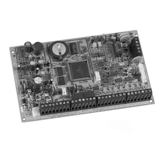
- Page 49 PCB LAYOUT When i nstall ing the bus wi res in a n oisy en viron ment, or whe n con nectin g th e bu s a cross sepa rate bui ldi ngs, you mu st u se a shi eld ed cabl e.
- Page 50 CONNECTING THE BUS IN NOISY ENVIRONMENTS When installing the bus wires in proximity to high electrical interference such as neon lights, motors, high-voltage wiring, transformers, or if connecting the bus across separate buildings, you must use shielded cables. Connect the shielded cable as detailed below: Within the Same Building: Strip the outer jacket at one end of the shielded cable to expose the shield and connect the shield to the control panel ground (not the dialer ground), while leaving the shield at the other end of the cable open (floating).
- Page 51 NOTES __________________________________________________________________________________ __________________________________________________________________________________ __________________________________________________________________________________ __________________________________________________________________________________ __________________________________________________________________________________ __________________________________________________________________________________ __________________________________________________________________________________ __________________________________________________________________________________ __________________________________________________________________________________ __________________________________________________________________________________ __________________________________________________________________________________ __________________________________________________________________________________ __________________________________________________________________________________ __________________________________________________________________________________ __________________________________________________________________________________ __________________________________________________________________________________ __________________________________________________________________________________ __________________________________________________________________________________ __________________________________________________________________________________ __________________________________________________________________________________ __________________________________________________________________________________ __________________________________________________________________________________ __________________________________________________________________________________ __________________________________________________________________________________ __________________________________________________________________________________ __________________________________________________________________________________ __________________________________________________________________________________ __________________________________________________________________________________ __________________________________________________________________________________ __________________________________________________________________________________ __________________________________________________________________________________ __________________________________________________________________________________ __________________________________________________________________________________ __________________________________________________________________________________ __________________________________________________________________________________ __________________________________________________________________________________ __________________________________________________________________________________ __________________________________________________________________________________ __________________________________________________________________________________ __________________________________________________________________________________ __________________________________________________________________________________ __________________________________________________________________________________...
-
Page 52: Trouble Display
Trouble Display STEP 1: From “normal mode”, press the [ ] key. TR BL STEP 2: Press the key corresponding to the trouble Group you wish to view. [1]: S [2]: C ROUBL E ROUP YST EM ROUBL E ROUP OMMUNICA TOR [1] AC Failure [4] Bell Current Limit...
Need help?
Do you have a question about the Digiplex NE DGP-NE96 and is the answer not in the manual?
Questions and answers