Paradox DGP2-641 Reference And Installation Manual
Lcd & access control lcd keypad (v1.0)
Hide thumbs
Also See for DGP2-641:
- System manager's manual (32 pages) ,
- User manual (7 pages) ,
- User quick reference manual (2 pages)

Related Manuals for Paradox DGP2-641


Summary of Contents for Paradox DGP2-641
- Page 1 LCD & Access Control LCD Keypad (V1.0) DGP2-641 / DGP2-641AC Reference and Installation Manual...
- Page 2 © 2002 Paradox Security Systems Ltd. Digiplex and DigiplexNE are trademarks of Paradox Security Systems PosiPIN is a trademark of Position Technology...
-
Page 3: Table Of Contents
TABLE OF CONTENTS 1.0 INTRODUCTION ............4 1.1 Specifications ..............5 2.0 INSTALLATION ............. 6 2.1 Connecting Keypad Zones ..........6 2.2 Programmable Output ............7 3.0 PROGRAMMING ............12 3.1 Entering Module Programming Mode ......12 3.2 Programming Methods ............ 13 3.2.1 Feature Select Programming .......... - Page 4 4.12 Keypad Tamper Enable ..........18 4.13 Network Voltmeter ............19 5.0 FEATURES FOR DGP2-641 ONLY ......20 5.1 PGM State ............... 20 5.2 PGM Deactivation Mode ..........20 5.3 PGM Base Time .............. 21 5.4 PGM Override ..............21 5.5 PGM Timer ..............21 5.6 PGM Activation Event .............
- Page 5 6.4.6 Beep Timer For Door Left Open Alarm ....... 31 6.5 Door Forced Open Options ..........31 6.5.1 Door Forced Open Access Alarm ........31 6.5.2 Door Forced Open Feedback ..........32 6.5.3 Beep Timer For Door Forced Open Alarm ......32 6.6 Access Control PIN Entry Option ........
-
Page 6: Introduction
1.0 INTRODUCTION ® Thank you for choosing Paradox Security Systems. The Digiplex™/ DigiplexNE Security Systems are advanced technology security systems that will provide reliable security protection and powerful features that are easy to use. The elegant and user-friendly Digiplex™/DigiplexNE LCD Keypad will allow easy access to the security system's functions and information at the touch of a button. -
Page 7: Specifications
Yes (also used to deactivate locate) LCD: Super Twisted Nematic display (STN), wide viewing angle, 2 lines of 16 characters, backlight and contrast adjustable Compatibility: DGP2-641: Any Digiplex/DigiplexNE Control Panel DGP2-641AC: Any DigiplexNE control panel or Digiplex control panel V2.20ACC and higher Digiplex/DigiplexNE LCD Keypad... -
Page 8: Installation
2.0 INSTALLATION The LCD keypads (DG2P-641 and DGP2-641AC) are connected to the control panel's network in a star and/or daisy chain configuration. This 4-wire communication network provides power and two-way communication between the control panel and all modules connected to it. Connect the four terminals labeled red, black, green and yellow of each keypad to the corresponding terminals on the control panel (refer to Figure 1 on page 8). -
Page 9: Programmable Output
to a zone in the control panel and the zone's parameters must be defined. For more information on zone assignment, please refer to the Digiplex or DigiplexNE Reference & Installation Manual. Please note that even with the ATZ (zone doubling) feature enabled, the keypad supports only one detection device. - Page 10 Figure 1: Connecting the Keypad and Keypad Zone 8 Reference & Installation Manual...
- Page 11 Figure 2: Typical Access Control Installation (DGP2-641AC) Figure 3: Access Control Overview (DGP2-641AC) Digiplex/DigiplexNE LCD Keypad...
- Page 12 Figure 4: Access Control Connections (DGP2-641AC) 10 Reference & Installation Manual...
- Page 13 Figure 5: Connecting a Shielded Routing Cable Digiplex/DigiplexNE LCD Keypad...
-
Page 14: Programming
3.0 PROGRAMMING Programming the DGP2-641 or DGP2-641AC LCD keypads is simple. Enter the Module Programming Mode, enter the desired section followed by the required data. When programming the keypad, use the keypad’s programming sheets (found in the Digiplex/ DigiplexNE Modules’ Programming Guide) to keep track of which sections were programmed and how. -
Page 15: Programming Methods
3.2 PROGRAMMING METHODS The following methods can be used when programming the keypad: 3.2.1 F EATURE ELECT ROGRAMMING Some sections are programmed by enabling or disabling options. Within the sections, numbers from [1] to [8] represent a specific keypad option. Press the key corresponding to the desired option and the digit will appear in the display. -
Page 16: System Options
4.0 SYSTEM OPTIONS The following sections pertain to the programming of options belonging to both the DGP2-641 and DGP2-641AC Access Control LCD keypads. 4.1 PARTITION ASSIGNMENT [001]: O ECTION PTIONS Each keypad in the system can be assigned to one or more partitions. -
Page 17: Display Entry Delay Timer
Option [2] OFF= Will not display Exit Delay timer (default). Option [2] ON = LCD screen will display Exit Delay timer. 4.4 DISPLAY ENTRY DELAY TIMER [003]: O ECTION PTION Based on the user's needs, an Entry Delay Timer will be programmed to provide the user time to enter their User Access Code before the alarm is triggered. -
Page 18: Confidential Mode Timer
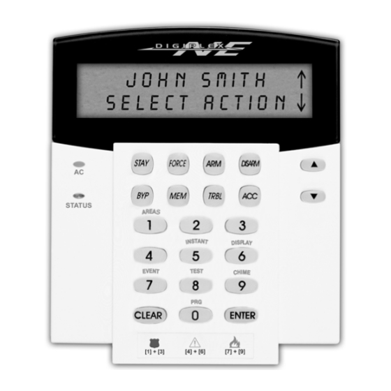
Section [003]: Option [4] OFF= Normal Mode Option [4] ON = Confidential Mode Option [5] OFF= LCD screen activated by entering an access code Option [5] ON = LCD screen activated by pressing a button Figure 6: LCD Screen 4.6 CONFIDENTIAL MODE TIMER [007] ECTION Section [007] determines the amount of time without action before... -
Page 19: Muting
4.8 MUTING [004]: O ECTION PTION The keypad can be programmed not to emit audible sounds, including Chimed zones. During Muting, the keypad will only emit the Confirmation Beep, Rejection Beep, and beep when a button is pressed. Option [1] OFF= Audible sounds (default). Option [1] ON = Mute. -
Page 20: Beep On Trouble
4.11 BEEP ON TROUBLE [005]: O ECTION PTIONS Potential troubles have been sorted into groups. With these options enabled, the keypad will emit an intermittent beep tone whenever a trouble condition from the Trouble Groups occurs in the system. The intermittent beep will remain activated until the user enters the Trouble Display or if the trouble is resolved. -
Page 21: Network Voltmeter
4.13 NETWORK VOLTMETER The Network Voltmeter provides a real-time display of the voltage so you can verify if the network is supplying sufficient power at the keypad’s location. The readings will appear on the LCD screen. A reading of 10.5V indicates that the voltage is too low. This may occur when too many modules are connected to the network, a module is installed too far from the panel or if the system is running on the battery. -
Page 22: Features For Dgp2-641 Only
5.0 FEATURES FOR DGP2-641 ONLY The following sections pertain to the programming of options belonging to the DGP2-641 LCD keypad only. 5.1 PGM STATE [006]: O ECTION PTION The keypad's on-board PGM can be set as normally open or normally closed. When an open PGM is activated, it will close the circuit from ground and enable any devices connected to it. -
Page 23: Pgm Base Time
5.3 PGM BASE TIME [006]: O ECTION PTION If the keypad's on-board PGM is set in PGM Timed Mode (see section 5.2 on page 20) you must define whether the value programmed in section [008] is in minutes or seconds. Option [3] OFF= PGM Base Time is 1 second (default). -
Page 24: Pgm Activation Event
5.6 PGM ACTIVATION EVENT [009] [012] ECTIONS The PGM Activation Event determines which event will activate the keypad's on-board PGM output. The specifies the EVENT GROUP event, the identifies the source, and the # and FEATURE GROUP START # sets the range within the Feature Group. Use the PGM Programming Table Digiplex/DigiplexNE... -
Page 25: Features For Dgp2-641Ac Only
6.0 FEATURES FOR DGP2-641AC ONLY The following sections pertain to the programming of options belonging to the DGP2-641AC Access Control LCD keypad only. 6.1 ASSIGNING DOORS TO PARTITIONS [002]: O ECTION PTIONS Although the keypad can be programmed to display the status of various partitions, the Access Control door can be assigned to one or more partition(s) in the alarm system. -
Page 26: Reader's Led To Follow Partition's Status
6.2.1 R ’ LED T ’ EADER OLLOW ARTITION TATUS [003]: O ECTION PTION The reader's LED can be programmed to flash according to the partition's status. When this feature is enabled, the reader’s red LED will flash when the partition is arming, in Exit Delay, in Entry Delay, in Burglar Alarm or in Fire Alarm. -
Page 27: Reader's Led Options Upon Access Granted
6.2.4 R LED O EADER PTIONS CCESS RANTED [006]: O ECTION PTION When the Access Control card is presented to the reader, the reader's LED can be programmed to turn green during the door’s unlocked period (or until the door closes) or extinguish briefly to indicate that the door is unlocked. -
Page 28: Door Unlocked Period Extension
6.3.3 D NLOCKED ERIOD XTENSION [009] ECTION The Door Unlocked Period Extension is the amount of time added to the Door Unlocked Period in section [008], which leaves the door unlatched longer. This will allow those with this feature enabled on their User Access Codes extra time to enter, which may be useful for the physically challenged or for seniors. -
Page 29: Card Activates Door Unlocked Schedule
users will have access during the days programmed in the control panel (refer to the Digiplex or DigiplexNE Reference & Installation Manual). Program the Start Time and End Time according to the 24- hour clock within the same day. Use Feature Select Programming to set the options representing the Days. -
Page 30: Door Left Open Options
schedule started at 7AM, the door remained locked from 7AM to 8AM. Once access was granted at 8AM, the door remained unlocked until 5PM. Option [1] OFF= The Schedule activates without Card (default). Option [1] ON = Card activates Door Unlocked Schedule. 6.4 DOOR LEFT OPEN OPTIONS The Door Left Open Options allow you to program how the system will react to an Access Control door left open. -
Page 31: Door Left Open Interval Before Access Alarm
6.4.2 D NTERVAL EFORE CCESS LARM [010] ECTION The Door Left Open Interval is the time that a door can remain open after an Access Granted or a Request for Exit without generating an Access Alarm. Enter any value between 001 and 255 to determine the number of seconds the door may remain open before the Access Alarm is triggered. -
Page 32: Door Left Open Alarm Feedback
Figure 7: Pre-Alarm example 6.4.5 D LARM EEDBACK [004]: O ECTION PTIONS An Access Control door is programmed with a Door Left Open Interval (see section 6.4.2 on page 29). Once this interval has expired, the Door Left Open Alarm can be either audible or silent and will either beep as long as the Access Alarm is occurring or follow the Beep Timer in section [012]. -
Page 33: Beep Timer For Door Left Open Alarm
6.4.6 B IMER LARM [012] ECTION This beep timer determines the amount of time the Door Left Open Alarm will beep. Once the Door Left Open Interval (see section 6.4.2 on page 29) has expired, the Door Left Open Alarm (see section 6.4.5 on page 30) will be triggered. Enter any value between 001 and 255 to determine the number of seconds the Access Alarm will beep. -
Page 34: Door Forced Open Feedback
6.5.2 D ORCED EEDBACK [004]: O ECTION PTIONS The Access Alarm can be either audible or silent and will either beep as long as the Access Alarm is occurring or follow the Beep Timer in section [013]. The sound of the Door Forced Open Alarm resembles the rapid beep generated during the last ten seconds of the Exit Delay. -
Page 35: Configuring The Posipin's Keypad
enter their PIN on the PosiPIN reader. If section [006] option [4] is OFF, the user must present their access control card to the reader and enter their PIN on the keypad. Option [4] OFF= User enters their PIN on the keypad (default). Option [4] ON = User enters their PIN on the PosiPIN. -
Page 36: Message Programming
7.0 MESSAGE PROGRAMMING [101] [148], [200] [204], and [301] [396] ECTIONS Each section contains one message with a maximum of 16 characters. For more details and to record any changes, use the Digiplex/DigiplexNE Modules’ Programming Guide. Section [101] to [148] = “Zone 01” to “Zone 48” respectively Section [200] = “Paradox Family”... -
Page 37: Special Function Keys
The DigiplexNE control panel has up to 8 partitions, 96 zones and up to 999 user codes. The LCD keypad only allows you to program the messages for up to 4 partitions, 48 zones and 96 user codes. The rest of the messages can be programmed directly into the DigiplexNE control panel. - Page 38 Table 2: Special Characters Catalog 36 Reference & Installation Manual...
-
Page 39: Glossary
8.0 GLOSSARY Access Alarm: An audible or silent warning generated by the reader to indicate that a protected door has not closed within the programmed time allowed or that a protected door was opened without an “Access Granted” or “Request for Exit” signal. If the Access Alarm is programmed to be audible, the reader assigned to the door can beep. - Page 40 in the Event Buffer and can be reported to a Monitoring Station. Door Left Open: Each Access Control door is programmed with a period of time it is allowed to remain open. Once the door has been open past this time limit, an Access Alarm will be triggered (see Access Alarm).
- Page 41 Holidays: Days programmed in the control panel that are not considered normal work days, such as legal, religious, and feast days. Pre-Alarm: A beep tone warning that an Access Alarm will be generated if a protected door is not closed within a specified period.
- Page 42 Warranty The Seller warrants its products to be free from defects in materials and workmanship under normal use for a period of one year. Except as specifically stated herein, all express or implied warranties whatsoever, statutory or otherwise, including without limitation, any implied warranty of merchantability and fitness for a particular purpose, are expressly excluded.
- Page 44 PRINTED IN CANADA - 04/2002 DGP2641-EI07...
Need help?
Do you have a question about the DGP2-641 and is the answer not in the manual?
Questions and answers