Advertisement
Quick Links
Download this manual
See also:
Instruction Manual
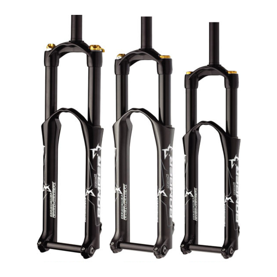
Features
TECHNICAL CHARACTERISTICS
Fork with Ø32 mm legs with spring and
hydraulic rebound damping.
Adjustment of the hydraulic rebound
braking through the knob on the top of the
right leg.
Adjustment of the air preload on the right
leg.
The ETA cartridge in the left leg makes it
possible to limit the extension blocking the
rebound of the fork.
The stanchion tubes are pressed into the
crown with a cryogenic process.
New sliding system to improve the stiffness
and operation.
Magnesium alloy cast one-piece assembly,
CNC machined for lighter weight and more
stiffness.
Components subjected to friction are
lubricated and cooled by means of a
special oil.
Steer tube: steel or reinforced aluminium,
1-1/8", threadless.
Crown: BAM® aluminium alloy forged and
CNC machined.
1/45
Z1 Free Ride
Stanchions: aluminium.
Springs: constant pitch.
Sliding bushes: made of friction free and
wear free material.
Seals: computer designed oil seals that
guarantee the maximum seal in any
condition.
Oil: special formulated oil that prevents
foam and keeps the viscosity unchanged
while offering high performance; free from
static friction.
Dropout type: Standard or (optional) QR20
Plus in the standard version or in the new
"With Bolt" version.
Disk brake mount: XC International
Standard for 6" disk.
Options: integrated fender.
BAM®: Bomber Aerospace Material:
special alloy coming from the aerospace
industry.
Advertisement

Related Manuals for Marzocchi Z1 Free Ride


Summary of Contents for Marzocchi Z1 Free Ride
- Page 1 Features Z1 Free Ride TECHNICAL CHARACTERISTICS Stanchions: aluminium. Fork with Ø32 mm legs with spring and Springs: constant pitch. hydraulic rebound damping. Sliding bushes: made of friction free and Adjustment of the hydraulic rebound wear free material. braking through the knob on the top of the right leg.
- Page 2 Features Z1 Free Ride 2/45...
- Page 3 Warning Z1 Free Ride INSTRUCTIONS FOR USE GENERAL REGULATIONS FITTING THE FORK ONTO THE FRAME INSTALLING THE DISK BRAKE SYSTEM ASSEMBLING THE FENDER ASSEMBLING THE WHEEL ON FORKS WITH STANDARD DROPOUTS ASSEMBLING THE WHEEL ON FORKS WITH QR20 PLUS DROPOUTS ASSEMBLING THE WHEEL ON FORKS WITH QR20 "WITH BOLT"...
- Page 4 Warning Z1 Free Ride INSTRUCTIONS FOR USE MARZOCCHI forks are based on an advanced technology coming from the company’s years long experience in the professional mountain bike industry. For the best results, it is advisable to inspect and clean the area below the dust...
- Page 5 Warning Z1 Free Ride GENERAL REGULATIONS damage the bolts and screws making it impossible to unscrew them. · After a complete breakdown, always use new MARZOCCHI seals when · Use the right size and sort of screwdriver reassembling. to unscrew slotted or crosshead screws.
- Page 6 A wrong installation can be dangerous for the rider. Marzocchi does not guarantee the assembly and accepts no liability for damage and/or accidents arising from a wrong installation. The steer tube must be pressed into the crown;...
- Page 7 INSTALLING THE DISK BRAKE SYSTEM Installing the brake system is a very delicate operation that must be carried out at our specialised service centres only. Marzocchi does not guarantee the installation and accepts no liability for damage and/or accidents arising from a wrong installation...
- Page 8 Warning Z1 Free Ride ASSEMBLING THE FENDER The fender can be supplied with the fork or purchased separately. Assemble the fender (A) by inserting the small support bush (C) between the screw and the fender as shown, and by tightening the screws (B) with an 8mm hexagonal spanner to the required torque (8±1 Nm).
- Page 9 Warning Z1 Free Ride ASSEMBLING THE WHEEL ON FORKS WITH STANDARD DROPOUTS Install the wheel following the instructions of the bike’s manufacturer. A good and reliable operation of the fork and all of the parts linked to it mainly depend on the correct fixing of the front wheel.
- Page 10 Warning Z1 Free Ride ASSEMBLING THE WHEEL ON FORKS · Verify the supporting bushes (E) stay WITH QR20 PLUS DROPOUTS correctly. A good and reliable operation of the fork · Check the correct fork-wheel alignment by and all of the parts linked to it mainly fully compressing the fork a few times.
- Page 11 Warning Z1 Free Ride ASSEMBLING THE WHEEL ON FORKS Close the locking device (M) and tighten WITH QR20 "WITH BOLT" DROPOUTS both screws (L) with a 6mm Allen wrench. A good and reliable operation of the fork and all of the parts linked to it mainly depend on the correct fixing of the front wheel.
- Page 12 Diagnostic Z1 Free Ride 12/45...
- Page 13 Disassembling Z1 Free Ride REMOVING THE TOP CAP – RIGHT LEG REMOVING THE TOP CAP – LEFT LEG DRAINING THE OIL BREAKING DOWN THE CROWN-STANCHION UNIT / ARCH-SLIDER ASSEMBLY REMOVING THE CARTRIDGE – LEFT LEG REMOVING THE ETA CARTRIDGE - LEFT LEG...
- Page 14 Disassembling Z1 Free Ride REMOVING THE TOP CAP - RIGHT LEG · With a 2mm Allen wrench loosen screw (1 · Remove first the screw (1), then the adjusting knob (3). · Fully unscrew the lock cap (4), using a 21mm socket spanner.
- Page 15 Disassembling Z1 Free Ride Push washer (6) and the preload tube (7) downwards so you can reach locknut (5) with a 10mm spanner. · Holding locknut (5) with the 10mm spanner, use the 21mm spanner to unscrew the lock cap (4) completely.
- Page 16 Disassembling Z1 Free Ride REMOVING THE TOP CAP – LEFT LEG · With a 2mm Allen wrench loosen screw (1 · Remove first the screw (1), then the ETA control knob (3). · Fully unscrew the lock cap (4) using a 21mm socket spanner.
- Page 17 Disassembling Z1 Free Ride Push washer (6) and the preload tube (7) downwards so you can reach locknut (5) with a 10mm spanner. · Holding locknut (5) with the 10mm spanner, use the 21mm spanner to unscrew the lock cap (4) completely.
- Page 18 Disassembling Z1 Free Ride DRAINING THE OIL · Remove washer (3), the preload tube (1) and spring (2) from the right leg. · Remove washer (13), the preload tube (11 ), and spring (12) from the left leg. · Free the fork from the vice and tip it into a container of a suitable size to drain the oil;...
- Page 19 Disassembling Z1 Free Ride BREAKING DOWN THE CROWN-STANCHION UNIT / ARCH-SLIDER ASSEMBLY Use the special spanner to remove the bottom nuts. Do not use other tools. Using the special 12mm spanner (A), loosen the two bottom nuts (1). Remove the bottom nuts (1) and the O-rings (2).
- Page 20 Disassembling Z1 Free Ride · Pull the crown-stanchion unit (3) off the arch-slider assembly (4). 20/45...
- Page 21 Disassembling Z1 Free Ride REMOVING THE HYDRAULIC CARTRIDGE - RIGHT LEG · Loosen and remove nut (1) with a 10mm spanner with fixed jaws. The hydraulic cartridge (5) has been sealed through machining and cannot be overhauled. In the case of faults or a malfunctioning, this cartridge must be replaced.
- Page 22 Disassembling Z1 Free Ride REMOVING THE ETA CARTRIDGE - LEFT LEG · Loosen and remove nut (1) with a 10mm spanner with fixed jaws. The ETA cartridge (5) has been sealed through machining and cannot be overhauled. In the case of faults or a malfunctioning, this cartridge must be replaced.
- Page 23 Disassembling Z1 Free Ride REMOVING THE SEALS · Remove the dust seal (1) from its seat, using a small flat-tip screwdriver. · With the same screwdriver prize off the metal stop ring (2). Take great care not to damage the...
- Page 24 Disassembling Z1 Free Ride Protect the upper part of the slider with the special tool (A). With a screwdriver prize the sealing ring (3) off. Remove the sealing ring (3). Take great care not to damage the internal surfaces of the arch-slider assembly when removing the sealing ring.
- Page 25 Disassembling Z1 Free Ride Protect the upper part of the slider with the special tool (A). With a screwdriver prize the sealing ring (3) off. Remove the sealing ring (3). Take great care not to damage the internal surfaces of the arch-slider assembly when removing the sealing ring.
- Page 26 Disassembling Z1 Free Ride REMOVING THE GUIDE BUSHES Use the special extractor to remove the guide bushes. Do not use other tools. Fit the aluminium bush (A) to the extractor keeping the large diameter side towards the edge opposite to the striker.
- Page 27 Assembling Z1 Free Ride ASSEMBLING THE GUIDE BUSHES 27/45...
- Page 28 Assembling Z1 Free Ride ASSEMBLING THE GUIDE BUSHES Insert the guide bushes using the special introducers (short type for the top bush and long type for the bottom bush, both with a white finish). Do not use other tools. Fit first the bottom bushes, then the top bushes.
- Page 29 Assembling Z1 Free Ride Using the short introducer (B) fit the top bush (2). Using a hammer knock the introducer (B) into the arch-slider assembly. 29/45...
- Page 30 Assembling Z1 Free Ride ASSEMBLING THE SEALS · Fit the dust seal (4) in its seat. · Smear the dust seal and the sealing ring with some grease. · Refit the sealing ring (3) using the special introducer (A). · Using a hammer knock in the introducer (A ) and drive the sealing ring home into the arch-slider assembly.
- Page 31 Assembling Z1 Free Ride · With a small tip screwdriver mount the stop ring (2) and check it fits perfectly into its groove. Take great care not to damage the internal surfaces of the arch-slider assembly when fitting the stop ring.
- Page 32 Assembling Z1 Free Ride MOUNTING THE HYDRAULIC CARTRIDGE - RIGHT LEG · Screw down nut (1) without tightening. 32/45...
- Page 33 Assembling Z1 Free Ride ASSEMBLING THE ETA CARTRIDGE - LEFT LEG · Screw down nut (1) without tightening. 33/45...
- Page 34 Assembling Z1 Free Ride ASSEMBLING THE CROWN-STANCHION UNIT / ARCH-SLIDER ASSEMBLY A special spanner shall be used to assemble the bottom nut. Do not use other tools. · Fit the dust seals (11) to the stanchions. · Insert the crown-stanchion unit (3) in the arch-slider assembly (4).
- Page 35 Assembling Z1 Free Ride · Fit the complete hydraulic cartridge (10) in the right leg. · Fit the complete ETA cartridge (9) in the left leg. · With the special 12mm spanner (A), tighten the bottom nut (1) with O-ring (2) of both legs to the recommended tightening torque (11 Nm±1).
- Page 36 Assembling Z1 Free Ride · Re-assemble the dust seals (11) in their seats using the special introducer (A). 36/45...
-
Page 37: Filling With Oil
Assembling Z1 Free Ride FILLING WITH OIL · Put the fork in the vice in vertical position. · Lower the crown-stanchion unit on the arch-slider assembly. · Prepare the quantity of oil to pour into the fork leg (see table). - Page 38 Assembling Z1 Free Ride · Lift the crown-stanchion unit on the arch-slider assembly. · Insert spring (2), the preload tube (1) and washer (3) in the right leg. · Insert spring (12), the preload tube (11) and washer (13) in the left leg.
- Page 39 Assembling Z1 Free Ride MOUNTING THE TOP CAP - RIGHT LEG · Screw the lock cap (4) down on the cartridge rod without tightening being very careful not to damage the O-ring. Push washer (6) and the preload tube (7) downwards so you can reach locknut (5) with a 10mm spanner.
- Page 40 Assembling Z1 Free Ride · With the 21mm socket spanner, tighten the lock cap (4) on the steering crown to the recommended tightening torque (20 Nm ±1). · Fit the adjusting knob (3) and screw (1). · Using the 2mm Allen wrench, tighten screw (1) to the recommended tightening torque (2 Nm ±...
- Page 41 Assembling Z1 Free Ride MOUNTING THE TOP CAP – LEFT LEG · Screw the lock cap (4) down on the ETA cartridge rod without tightening being very careful not to damage the O-ring. Push washer (6) and the preload tube (7) downwards so you can reach locknut (5) with a 10mm spanner.
- Page 42 Assembling Z1 Free Ride · With the 21mm socket spanner, tighten the lock cap (4) on the steering crown to the recommended tightening torque (20 Nm ±1). · Fit the ETA control lever (3) and screw (1). · Using the 2mm Allen wrench, tighten screw (1) to the recommended tightening torque (2 Nm ±...
-
Page 43: Rebound Adjustment
Settings Z1 Free Ride REBOUND ADJUSTMENT ETA (TRAVEL LIMITING DEVICE) 43/45... - Page 44 Settings Z1 Free Ride REBOUND ADJUSTMENT With the adjuster (A), at the top of the right leg, you can adjust the rebound damping. Turning the adjuster modifies the hydraulic configuration of the internal valves and lets more or less oil flow through.
- Page 45 Settings Z1 Free Ride ETA (TRAVEL LIMITING DEVICE) The ETA cartridge fitted to the left leg, allows reducing the fork rebound limiting the fork travel to 30 mm. Turning the control (A) clockwise activates the ETA cartridge function. Turning the control (A) counter-clockwise brings the fork back to normal function and deactivates the limiting device.
Need help?
Do you have a question about the Z1 Free Ride and is the answer not in the manual?
Questions and answers