
Related Manuals for COMBA mPICO Series


Summary of Contents for COMBA mPICO Series
- Page 1 SERIES USER MANUAL mPICO SERIES QE: 1-0-0 Comba Telecom Ltd.
- Page 2 The information contained herein is the responsibility of and is approved by the following, to whom all enquiries should be directed in the first instance: This is an unpublished work the copyright in which vests in Comba International ("Comba"). All rights reserved.
-
Page 3: Table Of Contents
USER MANUAL FOR mPICO SERIES CONTENTS Section Page CONTENTS ........................3 INDEX TO FIGURES AND TABLES.................. 5 HISTORY ......................... 7 GLOSSARY OF TERMS ....................8 SAFETY NOTICES AND ADMONISHMENTS ..............9 GENERAL INFORMATION ..................... 10 EQUIPMENT DESCRIPTION..................12 SYSTEM DIAGRAM ....................... 12 EQUIPMENT LAYOUT .................... - Page 4 USER MANUAL FOR mPICO SERIES 5.3.8 MISCELLANEOUS ......................39 ALARM ........................... 39 NMS ..........................40 5.5.1 SITE ID ........................... 40 5.5.2 OMC ..........................41 5.5.3 WIFI (CHANGE CONNECTION PASSWORD) ..............45 COMMISSION PROCEDURE ..................45 LOCAL AND REMOTE CONNECTIONS TO OMT ............49 5.7.1...
-
Page 5: Index To Figures And Tables
USER MANUAL FOR mPICO SERIES INDEX TO FIGURES AND TABLES Figure 1: Views of Single Band mPICO Enclosure ................. 11 Figure 2: Views of Dual/Triple Band mPICO Enclosure ................11 Figure 3: Single Band mPICO System Diagram ..................12 Figure 4: Triple Band mPICO System Diagram ..................12 Figure 5: Single Band mPICO Internal Layout .................. - Page 6 USER MANUAL FOR mPICO SERIES Figure 57: Auto Connection1 ......................... 51 Figure 58: Auto Connection2 ......................... 51 Figure 59: General Version ........................51 Figure 60: Connection via Ethernet ......................52 Figure 61: Remote Connection ......................52 Figure 62: OMT Main Window ....................... 53 Figure 63: Switch ...........................
-
Page 7: History
USER MANUAL FOR mPICO SERIES HISTORY Change No. Details Of Change 1-0-0 mPICO series user manual first created in Sep 2016. 1-0-1 Updated mobile APP connection in Mar 2017. ENU Status : 1-0-1 Copyright - refer to title page Page 7... -
Page 8: Glossary Of Terms
USER MANUAL FOR mPICO SERIES GLOSSARY OF TERMS Automatic Level Control Attenuation Antenna Feedback Cancellation Base Transceiver Station Cross Sectional Area Decibel Decibels relative to 1 mill watt Downlink Duplexer Donor Terminal E/O, O/E Electrical/Optical, Optical/Electrical Frequency Shift Keying Fiber Optical Unit... -
Page 9: Safety Notices And Admonishments
USER MANUAL FOR mPICO SERIES SAFETY NOTICES AND ADMONISHMENTS This document contains safety notices in accordance with appropriate standards. In the interests of conformity with the territory standards for the country concerned, the equivalent territorial admonishments are also shown. Any installation, adjustment, maintenance and repair of the equipment must only be carried out by trained, authorized personnel. -
Page 10: General Information
USER MANUAL FOR mPICO SERIES 1 GENERAL INFORMATION The mPICO Series Digital Pico Repeater (hereinafter called “mPICO”) is designed for single/dual/triple band network. It can wireless transmit, bi-directional amplify uplink and downlink signals and is designed for eliminating communicational coverage blind spots. -
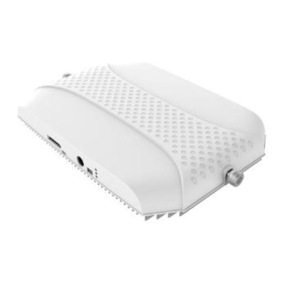
Page 11: Figure 1: Views Of Single Band Mpico Enclosure
USER MANUAL FOR mPICO SERIES 198.0 Figure 1: Views of Single Band mPICO Enclosure 41.5 316.0 Figure 2: Views of Dual/Triple Band mPICO Enclosure End of Section ENU Status : 1-0-1 Copyright - refer to title page Page 11... -
Page 12: Equipment Description
USER MANUAL FOR mPICO SERIES 2 EQUIPMENT DESCRIPTION SYSTEM DIAGRAM Integrated Module DL PA Filter (RF) Filter (RF) ADC/ ADC/ Duplexer (DT) FPGA Duplexer (MT) Filter (RF) Filter (RF) UL PA Monitor Module DC-DC converter MODEM Optional +12V Li-ion Power Adapter... -
Page 13: Equipment Layout
USER MANUAL FOR mPICO SERIES As shown in the above figure, the downlink BS signals go through DT port to the system and then to downlink by duplexer separation. The DL signals will go through digital filter. Then the DL signals will be sent to downlink PA to amplify power and filter via duplexer. -
Page 14: Equipment Constitution
USER MANUAL FOR mPICO SERIES Integrated Module(Slave) Combiner Integrated Module(Slave) Combiner Integrated Module(Master) Modem Modem Jumper LED Indicator Power Li-ion Battery Figure 7: Triple Band mPICO Internal Layout EQUIPMENT CONSTITUTION mPICO consists of the modules described as below: Table 1: Equipment Constitution... -
Page 15: Kit Of Parts
USER MANUAL FOR mPICO SERIES KIT OF PARTS For this system, the following are shipped: Table 2: Equipment KOP (Single Band) Product Identifier Description Quantity Remark Power Adaptor Mounting Rack MP-0832-5809 SMA-Male to N-Female Jumper RS-218WDT, 0.5m Power Supply Cable... -
Page 16: Installation
USER MANUAL FOR mPICO SERIES 3 INSTALLATION WARNINGS AND ALERTS Radio Frequency Energies There may be situations, particularly for workplace environments near high-powered RF sources, where recommended limits for safe exposure of human beings to RF energy could be exceeded. In such cases, restrictive measures or actions may be necessary to ensure the safe use of RF energy. -
Page 17: Site Planning Considerations
USER MANUAL FOR mPICO SERIES SITE PLANNING CONSIDERATIONS Site Considerations The repeater is designed for indoor installation and operation. Antenna separation For optimal operation, the physical separation of the MT and DT antennas should satisfy the condition for I > G +15dB, where I represents isolation between MT and DT ports. -
Page 18: Installation Procedures
USER MANUAL FOR mPICO SERIES INSTALLATION PROCEDURES 3.3.1 GOODS INWARDS INSPECTION Verify the number of packages received against the packing list. Check all packages for external damage; report any external damage to the shipping courier. If there is damage, a shipping agent should be present before unpacking and inspecting the contents because damage caused during transit is the responsibility of the agent. -
Page 19: Figure 9:Multi-Band Mpico Wall Mounting
USER MANUAL FOR mPICO SERIES Wall Plastic Plug Device Mounting Rack Fixed Bolt Screw(ST4x30) Figure 9:Multi-Band mPICO Wall Mounting Adapter mounting rack likes below, the distance between the fixed holes on the rack is 71mm. After installation, the adapter can put in the adapter mounting rack. Also the Li-ion battery can be fixed on the profile of rack. -
Page 20: Equipment Connectors
USER MANUAL FOR mPICO SERIES EQUIPMENT CONNECTORS 3.4.1 CONNECTORS +12V Single Band mPICO Power Li-ion Battery LED Indicator +12V Multi-Band mPICO Figure 11: Device Panel Interface Diagram The connection interfaces are shown below: Table 5: mPICO Connectors Connector Description SMA connector, for external donor antenna... -
Page 21: Grounding Connection
USER MANUAL FOR mPICO SERIES 3.4.2 GROUNDING CONNECTION Ground Connection To ensure safe operation of the product, a ground (earth) connection is required. For single phase AC power source, the product must be grounded by connecting the “earth wire” of the power cord to the ground terminal of the AC supply. -
Page 22: Connection Between Pc And Equipment
USER MANUAL FOR mPICO SERIES 3.4.5 CONNECTION BETWEEN PC AND EQUIPMENT The below shows the connection: Monitoring Center Wire/Wireless WCDMA/GSM Modem Network/PSTN Build-in Realize remote Wireless WCDMA/GSM monitor Modern Micro- Local Monitoring Figure 12: The Connection between Equipment and PC Note that when connect the Micro-USB with PC, the equipment should be power off and Li-ion battery output connector is disconnected. -
Page 23: Commissioning
USER MANUAL FOR mPICO SERIES 4 COMMISSIONING PRE-COMMISSIONING TASKS The equipment is easily commissioned, once the front cover is removed, programming of the equipment can be done either by press the one click smart setup button or software commissioning via Micro-USB interface. - Page 24 USER MANUAL FOR mPICO SERIES line & Inquiry Status Set Frequency and Bandwidth Signal Input Adjust Downlink ATT and Measure Downlink Output Power and Isolation Remote Connection to OMC Configure [Equipment ID] Comm. Comfig Select Monitoring Parameters Test-Call Double Check No Interference to BTS and...
-
Page 25: Table 7: Commissioning
USER MANUAL FOR mPICO SERIES Table 7: Commissioning Commissioning Tasks Observation Connect to Comba OMT. 1. On-line and Inquiry status Proceed if there is no alarm; else check the failure and attend to the alarm. 2. Set Frequency and ... -
Page 26: Omt
USER MANUAL FOR mPICO SERIES 5 OMT The equipment can be monitored and controlled by APP running on an Android mobile phone with WiFi connection or OMT software running on a local PC with local commissioning cable, remote connection to the equipment via wireless network. -
Page 27: Figure 14: Enter Password
USER MANUAL FOR mPICO SERIES Figure 14: Enter Password Select [mPico] and set up Wi-Fi hostspot for connection. Enter the Network SSID and password (Both default are CombaApp). Note: The default Network SSID and password is for first connection, suggest changing password after commissioning. -
Page 28: App Configuration
USER MANUAL FOR mPICO SERIES Figure 16: Wi-Fi hostspot After configuration is done successfully, the following window will pop up; click the site ID and access. If there have several equipments nearby, it will display a site ID list. Figure 17: Product Selection 5.1.2 APP CONFIGURATION... -
Page 29: Device Information
USER MANUAL FOR mPICO SERIES Figure 18: APP Main Window DEVICE INFORMATION 5.2.1 BASE INFO. Base Info includes current date/time, device temperature, equipment model, equipment type, serial no. and vendor ID. Click ‘Current Date/Time’ to input your local date and time information. The other parameters are read only. -
Page 30: Threshold
USER MANUAL FOR mPICO SERIES 5.2.3 THRESHOLD Figure 20: Threshold Config: Enter the required value in setting columns and click [Config] button to finish the configuration operation. The default value of [Battery Voltage Low Threshold] is 6.9V. And the default value of [Device Over- TEMP Threshold] is 80 C degree. -
Page 31: Alarm Control
USER MANUAL FOR mPICO SERIES 5.2.5 ALARM CONTROL Figure 22: Alarm Control Config: Enter the required value in setting columns and click [Config] button to finish the configuration operation. The default value of [Alarm Detect Duration] is 0. 0 and 254 are special, 0 means 1800 seconds and 254 means real time. -
Page 32: License
USER MANUAL FOR mPICO SERIES 5.2.7 LICENSE Figure 24: License License is for special product only, not for common product. 5.2.8 TRIGGER Figure 25: Trigger Control Config: Click to trigger required state. ENU Status : 1-0-1 Copyright - refer to title page... -
Page 33: Rf Parameter
USER MANUAL FOR mPICO SERIES RF PARAMETER It is recommended to configure the following RF parameters for the first installation. Figure 26: RF Parameters 5.3.1 SWITCH RF Switch is to enable/disable power for internal modules. When user checks and sets non-RF parameters, such as checking physical antenna connection, switching off will disable equipment power temporarily to protect PA in operation. -
Page 34: Frequency
USER MANUAL FOR mPICO SERIES Figure 27: Switch Config: Select the required state in setting columns of RF information window for RF switch, then press [Config] button to complete the configuration operation. 5.3.2 FREQUENCY Frequency is working band bandwidth setting. The value in [Max Value] column is the upper limit of the range, while the value in [Min Value] column is the lower limit of the range. -
Page 35: Isolation
USER MANUAL FOR mPICO SERIES Config: Enter the required value in setting columns and press [Config] button to finish the configuration operation. Select network type first, before setting bandwidth. Bandwidth setting rules: mPICO can support 2 working-bands of each band, in order to make sure the repeater can work normally, the main software protect the setting of frequency, the rules are shown as below: ... -
Page 36: Att
USER MANUAL FOR mPICO SERIES Figure 30:Isolation 5.3.4 ATT ATT adjustment includes UL/DL ATT adjustment. The purpose of adjusting the ATT is to adjust system gain. DL/UL ATT setting range: 0~30dB. Figure 31: ATT ENU Status : 1-0-1 Copyright - refer to title page... -
Page 37: Threshold
USER MANUAL FOR mPICO SERIES Config: Enter the required value in setting columns, and press [Config] button to finish the configuration operation. 5.3.5 THRESHOLD Threshold includes input power threshold, output power threshold. Users can set alarm threshold according to the specific situation. If the measured value is lower than the threshold lower limit or more than the threshold upper limit, the appropriate alarm will be generated. -
Page 38: Gain
USER MANUAL FOR mPICO SERIES Figure 33: Power 5.3.7 GAIN Gain is referring to the reading of downlink and uplink calculative gain. Figure 34: Gain ENU Status : 1-0-1 Copyright - refer to title page Page 38... -
Page 39: Miscellaneous
USER MANUAL FOR mPICO SERIES 5.3.8 MISCELLANEOUS Figure 35: Miscellaneous Isolation detection working mode includes working mode and testing mode. Note: Make sure is in working mode status; testing mode is for factory testing only. ALARM Alarm information operation is to select alarm parameters for monitoring. Alarm parameters include separate band alarm and common device alarm. -
Page 40: Nms
USER MANUAL FOR mPICO SERIES Figure 37: Common Device Alarm Config: Click the desired parameter and enable/disable of the desired parameters. Notice: [Enable] is to enable the alarm monitoring for system. Only if users enable the alarms, the alarms can be monitored by the OMC. -
Page 41: Omc
USER MANUAL FOR mPICO SERIES Table 8: Equipment ID Item Description Site ID is the unique equipment identification. It is a hexadecimal string of eight Site ID characters in the range of [00000000~FFFFFFFF]. e.g. 00000000 Site Sub ID is used for Master-Slave System. It is the unique identification of each Master/ Slave Unit and is a hexadecimal string of two characters in the range of [00~FF]. -
Page 42: Figure 41: Authentication
USER MANUAL FOR mPICO SERIES Figure 41: Authentication See the table below for configuration details of each parameter. ENU Status : 1-0-1 Copyright - refer to title page Page 42... -
Page 43: Table 9: Omc Config
USER MANUAL FOR mPICO SERIES Table 9: OMC Config. Item Description The Report No. is the SIM card number of the modem built into the OMC Server computer. The equipment will send alarm to this number. Alarm Report Phone If remote communication is needed via modem, users have to enable SMS mode and set the report phone No. -
Page 44: Figure 42: Location
Config: Click the desired parameter and trigger report. If Comba OMC platform had been set up, after OMC config parameter setting is done, trigger the new site report, Comba OMC platform will add the new site automatically. ENU Status : 1-0-1... -
Page 45: Wifi (Change Connection Password)
USER MANUAL FOR mPICO SERIES 5.5.3 WIFI (CHANGE CONNECTION PASSWORD) Figure 44: WiFi SSID Config: Enter the required value in setting columns and press [Config] button to finish the configuration operation. Both WiFi SSID and password default value are CombaApp. -
Page 46: Figure 46: General Setting
USER MANUAL FOR mPICO SERIES For each frequency band, the 2 working band bandwidth setting should not be overlap each other, if yes, they are forbade switching on working channel No. switch. Figure 46: General Setting Step 3: Click [Next] to enter to Mode select Screen shown. -
Page 47: Figure 47: Mode Select
USER MANUAL FOR mPICO SERIES Figure 47: Mode Select Figure 48: Isolation Detection Step 3: Click [Next] to enter to Gain Setting Screen shown. If select [Auto Setup] mode, the gain setting is automatically done, click next to finish. -
Page 48: Figure 49: Isolation Detection
USER MANUAL FOR mPICO SERIES Figure 49: Isolation Detection Step 3: Click [Next] to finish new site commissioning. Figure 50: Finish ENU Status : 1-0-1 Copyright - refer to title page Page 48... -
Page 49: Local And Remote Connections To Omt
USER MANUAL FOR mPICO SERIES LOCAL AND REMOTE CONNECTIONS TO OMT 5.7.1 CONNECTION FROM PC TO OMT Before accessing to the OMT, physical connection between the OMT software and the equipment must be made. A Micro-USB cable shall be applied for the connection. -
Page 50: Figure 53: Driver Installation 3
USER MANUAL FOR mPICO SERIES Figure 53: Driver Installation 3 Select ‘Microsoft Corporation’ in the Manufacturer list and select ‘Remote NDIS Compatible Device’ follow below. Figure 54: Driver Installation 4 Click ‘Next’ and wait, RNDIS Kitl will be installed successfully like below. -
Page 51: Local Connection To Omt
USER MANUAL FOR mPICO SERIES Figure 56: Password 5.7.2 LOCAL CONNECTION TO OMT After database configuration is done successfully, the following window will pop up. Click [Auto Connection] and select [Local connection via USB] for local connection. Figure 57: Auto Connection1... -
Page 52: Remote Connection To Omt
USER MANUAL FOR mPICO SERIES Figure 60: Connection via Ethernet Table 10: IP Setting Quick Look-up Table Items Default Value PC IP Address 195.60.16.X (X=1~253) Device IP Site Port NO. 7025 (default) PC Subnet Mask 255.255.255.0 Repeater IP Address 195.60.16.254 5.7.3 REMOTE CONNECTION TO OMT... -
Page 53: Omt Configuration
USER MANUAL FOR mPICO SERIES OMT CONFIGURATION After entering the OMT main screen, click the “Connect” button on the toolbar, to connect the equipment to the OMT. Successful connection will be indicated by a message “Online Ok” and equipment parameters can be read and/or set. -
Page 54: Frequency
USER MANUAL FOR mPICO SERIES Figure 63: Switch Config: Select the required state in setting columns of RF information window for RF switch, then press [Enter] or [Config] button to complete the configuration operation. Note: If you turn on the ‘Isolation Detection Switch’, please read the result on ‘Miscellaneous’; LED switch is used for controlling LED indicator. -
Page 55: Figure 65:Frequency Calculator
USER MANUAL FOR mPICO SERIES Figure 65:Frequency Calculator Channel NO. Setting rules: mPICO can support 2 working-bands of each band, in order to make sure the repeater can work normally, the frequency setting rules are shown as below: Before switch on the channel switch, please check the channel frequency and it shall not be overlapping with other channels which have turned on. -
Page 56: Att
USER MANUAL FOR mPICO SERIES 5.9.3 ATT ATT adjustment includes UL/DL ATT adjustment. The purpose of adjusting the ATT is to adjust system gain. DL/UL ATT setting range: 0~30dB. Figure 67: ATT Config: Select the required value in setting columns of RF information window for ATT, and press [Enter] or [Config] button to finish the configuration operation. -
Page 57: Power
USER MANUAL FOR mPICO SERIES 5.9.5 POWER Power is referring to the reading of downlink input/output power. Figure 69: Power Read: Press [Read] to read all the values of the parameters in the window. Press [Auto-Read (F4)] to read values continuously. -
Page 58: Miscellaneous
USER MANUAL FOR mPICO SERIES Figure 71: Temperature Read: Press [Read] to read all the values of the parameters in the window. Press [Auto-Read (F4)] to read values continuously. 5.9.8 MISCELLANEOUS Isolation is referring to the reading of system isolation status. -
Page 59: Properties Info
USER MANUAL FOR mPICO SERIES Figure 73: Master Alarm Figure 74: Channel Alarm Config: Tick the check box of [Item select] and [Enable] of the desired parameters and click [config] button to finish configuration operation. Notice: [Enable] box is to enable the alarm monitoring for system. Only if users enable the alarm by ticking the [Enable] box, the alarms can be monitored by the OMC. -
Page 60: Comm. Config
USER MANUAL FOR mPICO SERIES Figure 75: Site ID See the table below for configuration details of each parameter. Table 11: Equipment ID Item Description Site ID is the unique equipment identification. It is a hexadecimal string of eight Site ID characters in the range of [00000000~FFFFFFFF]. -
Page 61: Table 12: Com.config
USER MANUAL FOR mPICO SERIES See the table below for configuration details of each parameter. Table 12: Com.Config. Item Description Select “Enable” or “Disable” from the drop down menu as shown to enable or Phone No. Checking disable the Phone Number Authentication feature. Refer to [Phone No.] in details. -
Page 62: Troubleshooting
USER MANUAL FOR mPICO SERIES 6 TROUBLESHOOTING Following installation and commissioning, troubleshooting tasks to handle alarms may be required. Here below is the alarm list of the equipment and diagnosis. Table 13: Alarm List and Diagnosis Alarm Diagnosis Check AC power cable and verify AC mains supply is normal. -
Page 63: Appendices
USER MANUAL FOR mPICO SERIES 7 APPENDICES APPENDIX A: TOOLS FOR INSTALLATION AND MAINTENANCE The following are the recommended list of tools new installation and routine maintenance: Slotted Screwdriver Philips Screwdriver Ring Spanner (Assorted size: 12~20mm) Electrically operated drill and masonry drill bits 12mm ... -
Page 64: Appendix B: Rma (Return Material Authorization) Form
USER MANUAL FOR mPICO SERIES APPENDIX B: RMA (RETURN MATERIAL AUTHORIZATION) FORM End of section End of Document ENU Status : 1-0-1 Copyright - refer to title page Page 64... - Page 65 USER MANUAL FOR mPICO SERIES ENU Status : 1-0-1 Copyright - refer to title page Page 65...
Need help?
Do you have a question about the mPICO Series and is the answer not in the manual?
Questions and answers