
Related Manuals for COMBA mBDA-200


Summary of Contents for COMBA mBDA-200
- Page 1 USER MANUAL MBDA-200 QE: 1-0-0 Comba Telecom Ltd.
- Page 2 The information contained herein is the responsibility of and is approved by the following, to whom all enquiries should be directed in the first instance: This is an unpublished work the copyright in which vests in Comba International ("Comba"). All rights reserved.
-
Page 3: Table Of Contents
USER MANUAL FOR MBDA-200 CONTENTS Section Page CONTENTS ..............................3 INDEX TO FIGURES AND TABLES ........................5 HISTORY ............................... 7 GLOSSARY OF TERMS ............................ 8 SAFETY NOTICES AND ADMONISHMENTS ..................... 8 GENERAL INFORMATION ..........................10 EQUIPMENT DESCRIPTION .......................... 11 SYSTEM DIAGRAM ............................11 EQUIPMENT LAYOUT .......................... - Page 4 USER MANUAL FOR MBDA-200 APPENDICES ............................... 53 APPENDIX A: TOOLS FOR INSTALLATION AND MAINTENANCE ..............53 APPENDIX B: RMA (RETURN MATERIAL AUTHORIZATION) ................. 54 ENU STATUS : 1-0-0 Copyright - refer to title page Page 4...
-
Page 5: Index To Figures And Tables
USER MANUAL FOR MBDA-200 INDEX TO FIGURES AND TABLES Figure 1: mBDA-200 ..............................10 Figure 2: System Diagram ............................11 Figure 3: Layout of mBDA ............................12 Figure 4: mBDA Screen ............................17 Figure 5: mBDA Rack ............................... 18 Figure 6: Remove Cover Plates ..........................18 Figure 7: PMU Installation ............................ - Page 6 USER MANUAL FOR MBDA-200 Figure 54: Commissioning Procedure –Isolation Detection Failed ..............47 Figure 55: Commissioning Procedure –Isolation Detection Finish ..............48 Figure 56: Commissioning Procedure – Subband bandwidth and Switch Setting .......... 49 Figure 57: Commissioning Procedure – DL Output Power Setting Screen ............. 49 Figure 58: Commissioning Procedure –...
-
Page 7: History
USER MANUAL FOR MBDA-200 HISTORY Change No. Details Of Change 1-0-0 This user manual first created in Jan 2014. ENU STATUS : 1-0-0 Copyright - refer to title page Page 7... -
Page 8: Glossary Of Terms
USER MANUAL FOR MBDA-200 GLOSSARY OF TERMS Automatic Level Control Attenuation Bi-direction Amplifier Base Station Base Transceiver Station Downlink Donor Terminal Fiber Optical Unit Graphic User Interface Identification Low Noise Amplifier Main Control Unit Mobile Terminal MTBF Mean Time Between Failures... - Page 9 USER MANUAL FOR MBDA-200 Any installation, adjustment, maintenance and repair of the equipment must only be carried out by trained, authorized personnel. At all times, personnel must comply with any safety notices and instructions. Specific hazards are indicated by symbol labels on or near the affected parts of the equipment. The labels conform to international standards, are triangular in shape, and are coloured black on a yellow background.
-
Page 10: General Information
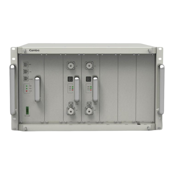
USER MANUAL FOR MBDA-200 1 GENERAL INFORMATION The mBDA-200 Band Selective Wireless Repeater is designed for operation in 850MHz and 1900MHz networks.Digital band-specific linear amplifier amplifies the desired BTS carriers and provides superior out-of-band rejection. Typical units with adjustable bandwidth are programmed to specific requirements of the network. -
Page 11: Equipment Description
USER MANUAL FOR MBDA-200 2 EQUIPMENT DESCRIPTION 2.1 SYSTEM DIAGRAM DL PA DL LNA Digital Frequency Selective Module UL PA UL LNA Donor Power Alarm Main Control Unit Supply Indicator Mobile Modem Mobile Mobile DL PA DL LNA Digital Frequency... -
Page 12: Equipment Layout
USER MANUAL FOR MBDA-200 2.2 EQUIPMENT LAYOUT 58.6 58.6 81.4 265.2 Figure 3: Layout of mBDA ENU STATUS : 1-0-0 Copyright - refer to title page Page 12... -
Page 13: Equipment Constitution
USER MANUAL FOR MBDA-200 2.3 EQUIPMENT CONSTITUTION mBDA consists of the following parts: Table 1: mBDA Components Module Description There are total 7 slots in the main chassis, where six slots for RF Units and mBDA-RACK Combiner Units, rest-one slot for Power & Monitoring Unit. -
Page 14: Installation
USER MANUAL FOR MBDA-200 3 INSTALLATION 3.1 WARNINGS AND ALERTS Radio Frequency Energies There may be situations, particularly for workplace environments near high-powered RF sources, where recommended limits for safe exposure of human beings to RF energy could be exceeded. In such cases, restrictive measures or actions may be necessary to ensure the safe use of RF energy. -
Page 15: Site Planning Considerations
USER MANUAL FOR MBDA-200 3.2 SITE PLANNING CONSIDERATIONS 3.2.1 SITE PLANNING Site Considerations There may be situations, particularly for workplace environments near high-powered RF sources, where recommended limits for safe exposure of human beings to RF energy could be exceeded. In such cases, restrictive measures or actions may be necessary to ensure the safe use of RF energy. -
Page 16: Installation Procedures
Without documentary evidence, a claim cannot be processed. Open and check each package against the packing list. For any shortage, contact Comba Telecom Systems. Do not remove items from packing materials until installation. - Page 17 USER MANUAL FOR MBDA-200 3.3.3 ASSEMBLING mBDA consists of 3 parts: Rack, PMU and RFUs. All the units are packed separately. Follow the steps below to assemble. RF Unit Power & Monitoring Unit Figure 4: mBDA Screen Step1: The rack with cover plates is shown as Figure 5. Please remove the cover plates, before installing related modules.
- Page 18 USER MANUAL FOR MBDA-200 Figure 5: mBDA Rack Figure 6: Remove Cover Plates Step 2: PMU installation: Insert PMU and fasten the screws. ENU STATUS : 1-0-0 Copyright - refer to title page Page 18...
- Page 19 USER MANUAL FOR MBDA-200 Figure 7: PMU Installation Step 3: RF Units installation: Insert RFUs and fasten the screws. Figure 8: RF Unit Installation Step 4: Finish Installation. ENU STATUS : 1-0-0 Copyright - refer to title page Page 19...
- Page 20 USER MANUAL FOR MBDA-200 Figure 9: mBDA Installation Finish 3.3.4 mBDA IN NORMAL EQUIPMENT CABINET mBDA is an indoor type device. It can be installed in normal equipment cabinet, the installation procedures are shown as below: Step 1: Make sure the equipment cabinet is available with pallet, and the pallet is fixed steadily (Equipment Cabinet nuts, screws and pallet are not provided.).
- Page 21 USER MANUAL FOR MBDA-200 Figure 10: Equipment Cabinet with Pallet Step 2: Install the mBDA on to the pallet. Figure 11: mBDA Installation Step 3: Attach the mBDA onto the cabinet with the recommended rack screws. ENU STATUS : 1-0-0...
- Page 22 USER MANUAL FOR MBDA-200 Figure 12: Secure the Screws Step 4: Finish installation. Figure 13: Finish Installaiton ENU STATUS : 1-0-0 Copyright - refer to title page Page 22...
- Page 23 USER MANUAL FOR MBDA-200 3.3.5 mBDA IN 19” RACK MOUNTING mBDA can also be installed in 19’’ rack mounting, the installation procedures are shown as below: Step 1: Install right angle bracket and left angle bracket on back of the mounting rack. (19” Rack nuts, screws and Angel Iron are not provided.) Use rack nuts and screws as recommended by rack...
- Page 24 USER MANUAL FOR MBDA-200 Figure 16: mBDA Installation Step 3: Attach the mBDA onto the rack with the recommended rack screws. Figure 17: Secure the Enclosure Step 4: Finish installation. ENU STATUS : 1-0-0 Copyright - refer to title page...
-
Page 25: Equipment Connectors
USER MANUAL FOR MBDA-200 Figure 18: Finish Installaiton 3.4 EQUIPMENT CONNECTORS The figure below presents the connectors of mBDA. ENU STATUS : 1-0-0 Copyright - refer to title page Page 25... - Page 26 USER MANUAL FOR MBDA-200 Figure 19: mBDA Front Panel Connectors Figure 20: mBDA Rear Panel Connectors Table 3: mBDA Connections Identifier Functional Description 1. OMT/LAN/RS485 OMT port is for local commissioning; LAN port is for remote connection; RS485 is for extension connection when adding extended equipment.
- Page 27 USER MANUAL FOR MBDA-200 Grounding connector. 8. FAN Fan inside 9. POWER Power switch. 10. AC100~240V AC power supply connector. ENU STATUS : 1-0-0 Copyright - refer to title page Page 27...
-
Page 28: Equipment Connection
USER MANUAL FOR MBDA-200 3.5 EQUIPMENT CONNECTION 3.5.1 GROUNDING CONNECTION WARNING! This unit must always be grounded. Consult an appropriate electrical inspection authority or an electrician if you are uncertain that suitable grounding is available. Do not connect power before grounding. - Page 29 USER MANUAL FOR MBDA-200 Power Connector Figure 22: mBDA Power Connection (Rear Panel) 3.5.4 EXTERNAL ALARM CONNECTION For EXT-ALM, this is a 4-pin connector. The following figure and table show the pin allocation and definition. Pin numbering are shown looking-into the connector on the enclosure.
-
Page 30: Commissioning
USER MANUAL FOR MBDA-200 4 COMMISSIONING 4.1 PRE-COMMISSIONING TASKS After equipment installation, perform the following steps before equipment powering and commissioning, check that the expected voltage, current, and power levels do not violate any ratings. Double check all connections including ground before applying power. Do not manipulate circuits or make changes when power is applied: ... -
Page 31: Commissioning Procedure
USER MANUAL FOR MBDA-200 4.3 COMMISSIONING PROCEDURE System commissioning can commence after the monitoring system has completed self initialization. The commissioning procedure is shown below: Connect and inquiry status Isolation detection Set channel No. Set monitor parameters Input power detection and adjust the direction of... - Page 32 USER MANUAL FOR MBDA-200 Table 6: Commissioning Procedure Commissioning Tasks Observation Activate the OMT Main window. The system Initialization will completed in about 2 minutes. 1. On-line and Inquiry status Click “Connect” button to enquire the repeater’s status. Proceed if ...
-
Page 33: Web Gui
5 WEB GUI mBDA can be monitored and controlled by WEB GUI, follow below contents to achieve system parameter setting and commissioning. WEB GUI CONNECTION Step 1: Connect PMU OMT port to PC RJ45 port with the supplied Ethernet cable to set up a physical connection. -
Page 34: Web Gui Introduction
Figure 28: Input User Name and Password WEB GUI INTRODUCTION After log in, the Web GUI main screen will appear. Figure 29: Web GUI Main Screen On Comba Web GUI Home Screen, there are four Menu bars: [Devices], [Commissioning], [Firmware] and [Management]. 5.2.1 [DEVICES] The [Devices] Screen shows the actual active modules of mBDA. - Page 35 USER MANUAL FOR MBDA-200 Figure 30: [Devices] Sceen PMU Main Management Screen Figure 31: Power & Monitoring Unit ENU STATUS : 1-0-0 Copyright - refer to title page Page 35...
- Page 36 USER MANUAL FOR MBDA-200 RF Unit Management Screen Figure 32: RF Unit NOTE: There are three statuses for PA Service: Normal, Recovery and Shutdown. If PA output power or reflected power exceeds the threshold, software will trigger Recovery: It will reset PA and then re-detect the PA output power and reflected power, if they are normal, the PA Service Status will turn to Normal, if PA output power or reflected power is still over the threshold, PA Service Status will turn to Recovery again.
-
Page 37: Commissioning]
USER MANUAL FOR MBDA-200 Figure 33: RF Unit Detail Information 5.2.2 [COMMISSIONING] A work flow of the commissioning process is shown on [Commissioning] Screen. Click the [Start] button, the software will guide you through the commissioning step by step. For details, please refer to chapter 5.3. -
Page 38: Firmware]
USER MANUAL FOR MBDA-200 5.2.3 [FIRMWARE] There are two functions on the [Firmware] bar: [upgrade] and [swap]. [Upgrade] is used to upgrade software, and [Swap] is to replace current firmware version to the previous one. Follow steps shown in below figure to upgrade firmware. -
Page 39: Management]
USER MANUAL FOR MBDA-200 Figure 37: [Firmware] Screen - Swap 5.2.4 [MANAGEMENT] Other parameters can be configured on [Management] Screen. Figure 38: [Management] Sceen There are nine function bars list in the left side of the [Mangement] Screen. Below figures are the introduction of each function bar. - Page 40 USER MANUAL FOR MBDA-200 Inport&Export Figure 39: Management – Import&Export The parameters that can be import/export as below: sub band, alarm enable, ATT value, RF switch, DL output power and so on. Import and Export can help users quickly configure mBDA parameters. For example, if one mBDA finished configuration, users can export its parameters and save as a file in PC, and then import this file to other mBDA to fast finish the device parameter setting.
- Page 41 USER MANUAL FOR MBDA-200 Figure 40: Management – IP Setting Note: For remote monitoring, the IP Address must be set correctly according to the location IP of remote connection. If more than one equipment is connected to the public network through the same router, the router’s local IP CANNOT be set as 192.168.8.*.
- Page 42 USER MANUAL FOR MBDA-200 Security Figure 42: Management – Security Click , [Modify Password] window will pop-up. Figure 43: Modify Password Note: Username cannot be modified. ENU STATUS : 1-0-0 Copyright - refer to title page Page 42...
- Page 43 USER MANUAL FOR MBDA-200 Device Reset Figure 44: Management – Device Reset . Device Reset Note: If users click , all the parameter and alarm will set to factory default value process will last about 2~4 minutes. For PMU monitor reset, users need to re-login WEB GUI.
- Page 44 USER MANUAL FOR MBDA-200 Device Info Figure 46: Management – Device Info Note: Users can input maximum 30 bytes characters in Device Info. Isolation Figure 47: Management – Isolation Note: This Step is the same as step3 of [Commissioning]. Users can check isolation again by clicking Check button.
-
Page 45: Commissioning Procedure
USER MANUAL FOR MBDA-200 Report Figure 48: Management – Report Note: Click Create to create report (The report cann’t create in IE browser.) and make sure the computer has installed PDF Reader software. If no, users will see nothing. - Page 46 USER MANUAL FOR MBDA-200 Step 2: Click to start the process. Figure 50: Commissioning Procedure – Site Info. Setting Step 3: Click , users can set the site information. Figure 51: Dev Info & Date/Time Dev Info mainly used to record device location and Date/Time provid a time reference. Click the Config Value of Date/Time, will update Date/time automatically.
- Page 47 USER MANUAL FOR MBDA-200 NOTE: At the end of first frequency band commissioning, user can start other frequency band commission. Figure 52: Commissioning Procedure – Isolation Detective Figure 53: Commissioning Procedure – Isolation Detective Confirm Figure 54: Commissioning Procedure –Isolation Detection Failed...
- Page 48 USER MANUAL FOR MBDA-200 Figure 55: Commissioning Procedure –Isolation Detection Finish Step 5: RF Setting Screen for setting subband bandwidths and switchs. ENU STATUS : 1-0-0 Copyright - refer to title page Page 48...
- Page 49 USER MANUAL FOR MBDA-200 Figure 56: Commissioning Procedure – Subband bandwidth and Switch Setting NOTE: For each RF module, the 3 subband bandwidth setting should not be overlap each other, if yes, only 1 subband can be turn on, other overlap subband is forbided to switch on by equipment.
- Page 50 USER MANUAL FOR MBDA-200 Figure 58: Commissioning Procedure – DL Output Power Setting NOTE: For each RF module, the total target output power of all subbands which channel switch is on must not exceed the nominal downlink output power (27, 30, 33dBm); if yes, Tips window will pop-up shown as Figure 59.
- Page 51 USER MANUAL FOR MBDA-200 Figure 60: Commissioning Procedure – Finish End of Section ENU STATUS : 1-0-0 Copyright - refer to title page Page 51...
-
Page 52: Maintenance
USER MANUAL FOR MBDA-200 6 MAINTENANCE The mBDA is designed for trouble-free operation and generally does not need maintenance. Maintenance activities should only be carried out by trained personnel. The equipment operation status can be observed remotely through OMC. Periodic inspection of the repeater equipment(s) is recommended, the recommended tasks includes: ... - Page 53 USER MANUAL FOR MBDA-200 7 APPENDICES APPENDIX A: TOOLS FOR INSTALLATION AND MAINTENANCE The following tools (not included in package) are required for installation or routine maintenance: Power Drill (for wall mount) Adjustable Wrench (0.31 inch~0.79 inch) ...
- Page 54 USER MANUAL FOR MBDA-200 7.2 APPENDIX B: RMA (RETURN MATERIAL AUTHORIZATION) End of Section End of Document FOR NAM OFFICE EMAIL, PLEASE INSERT: support.us@comba-telecom.com ENU STATUS : 1-0-0 Copyright - refer to title page Page 54...
- Page 55 USER MANUAL FOR MBDA-200 ENU STATUS : 1-0-0 Copyright - refer to title page Page 55...
Need help?
Do you have a question about the mBDA-200 and is the answer not in the manual?
Questions and answers