Table of Contents
Advertisement
Quick Links
GSM1800 BANDWIDTH ADJUSTABLE
This is an unpublished work the copyright in which vests in Comba International ("Comba"). All rights reserved.
The information contained herein is confidential and the property of Comba and is supplied without liability for errors or omissions.
No part may be reproduced, disclosed or used except as authorised by contract or other written permission. The copyright and the
foregoing restriction on reproduction and use extend to all media in which the information may be embodied.
RD-1820 QE
ENU Status : 1-0-0
EQUIPMENT MANUAL FOR RD-1820
RD-1820
REPEATER
EQUIPMENT MANUAL
The information contained herein is the
responsibility of and is approved by the
following, to whom all enquiries should
be directed in the first instance:
International Documentation Centre
Comba Telecom
Copyright - refer to title page
Page 1
Advertisement
Table of Contents

Related Manuals for COMBA RD-1820


Summary of Contents for COMBA RD-1820
- Page 1 This is an unpublished work the copyright in which vests in Comba International ("Comba"). All rights reserved. The information contained herein is confidential and the property of Comba and is supplied without liability for errors or omissions. No part may be reproduced, disclosed or used except as authorised by contract or other written permission. The copyright and the foregoing restriction on reproduction and use extend to all media in which the information may be embodied.
-
Page 2: Table Of Contents
SERVICING POLICY AND RETURN OF EQUIPMENT..............10 0.10 READERS COMMENTS ........................11 RD-1820 REPEATER INTRODUCTION................... 12 EQUIPMENT DESCRIPTION ......................13 RD-1820 FUNCTIONAL BLOCK DIAGRAM ..................13 EQUIPMENT LAYOUT ........................13 MANUFACTURING ENTITIES ......................15 KIT OF PARTS............................15 TECHNICAL SPECIFICATIONS ......................16 2.5.1... - Page 3 EQUIPMENT MANUAL FOR RD-1820 MAINTENANCE ............................ 39 APPENDICES ............................40 APPENDIX A: TOOLS ......................... 40 APPENDIX B: OMT INSTALLATION AND UN-INSTALLATION........... 41 7.2.1 ENVIRONMENT FOR OMT OPERATION..................41 7.2.2 INSTLLATION OF OMT EXPLORER ....................42 7.2.3 INSTALLING RD-1820 COMPONENT....................44 7.2.4...
-
Page 4: Index To Figures And Tables
Figure 16: Components selective window....................42 Figure 17: Installation of OMT explorer completed ..................43 Figure 18: Installation of RD-1820 component completed................44 Figure 19: RD-1820 component unistallation - confirmation................ 45 Figure 20: OMT Explorer uninstallation - acknowledgement ............... 45 Table 1: RD-1820 manufacturing entities..................... -
Page 5: History
0.4 HISTORY Change No. Details Of Change 1-0-0 Initial document created for CE certification and issued in May 2006. Updated base product name: RD-1820 = R-1810AC Copyright - refer to title page RD-1820 QE Page 5 ENU Status : 1-0-0... -
Page 6: Issue Control
EQUIPMENT MANUAL FOR RD-1820 0.5 ISSUE CONTROL Date 2006 Section Copyright - refer to title page RD-1820 QE Page 6 ENU Status : 1-0-0... -
Page 7: References
EQUIPMENT MANUAL FOR RD-1820 0.6 REFERENCES 0.6.1 RD-1820 datasheet Datasheet issued by PM on 19 May 2006. Control: 1-0-0/A1 0.6.2 R-1810AC QE 1-2-0 Equipment manual released in Oct 2005. Copyright - refer to title page RD-1820 QE Page 7 ENU Status : 1-0-0... -
Page 8: Glossary Of Terms
EQUIPMENT MANUAL FOR RD-1820 0.7 GLOSSARY OF TERMS Abbreviation Definition Automatic Level Control Attenuation Base Station Base Transceiver Station Decibel Decibels relative to 1 milliwatt Downlink Donor Terminal Duplexer EEPROM Electrically Erasable Programmable Read Only Memory Frequency Selector Global Standard for Mobile Communication... -
Page 9: Safety Notices And Admonishments
EQUIPMENT MANUAL FOR RD-1820 0.8 SAFETY NOTICES AND ADMONISHMENTS This document contains safety notices in accordance with appropriate standards. In the interests of conformity with the territory standards for the country concerned, the equivalent territorial admonishments are also shown. Any installation, adjustment, maintenance and repair of the equipment must only be carried out by trained, authorised personnel. -
Page 10: Servicing Policy And Return Of Equipment
Repair Material Authorization (a sample of this is in the appendix) completed giving the required information This request must be included with the item for repair, items for repair should be sent to the nearest Comba office: COMBA TELECOM SYSTEMS, LTD. -
Page 11: Readers Comments
EQUIPMENT MANUAL FOR RD-1820 0.10 READERS COMMENTS Whilst every endeavour is made to ensure the accuracy of this and all Comba documents, there is always the possibility that an inaccuracy or omission could occur. In order that any amendment/remedial action can be carried out promptly, we would appreciate your co–operation in filling out and returning a photocopy of this customer reply sheet as soon as possible. -
Page 12: Rd-1820 Repeater Introduction
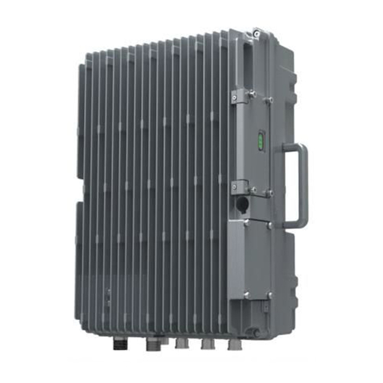
Comba’s remote control and monitoring system, via PC or wireless modem to the OMT/OMC. Internal Li-ion backup battery ensures alarm signals are sent out during power failure. The RD-1820 comes in a completely sealed, cast aluminum enclosure, suitable for operation in all weather conditions. -
Page 13: Equipment Description
Alarm Main Control Unit Supply BATT Indicator Computer with Modem Data card Wireless Modem External Power Figure 2: RD-1820 functional block diagram 2.2 EQUIPMENT LAYOUT DL LNA UL LNA Li-ion battery Filter Filter UL FS DL PA Distribution board Surge... - Page 14 EQUIPMENT MANUAL FOR RD-1820 Typical RD-1820 units consist of the following components: Frequency Selector (FS): Frequency selector (FS) can select the required signal and reject the other unwanted signals effectively. Power Amplifier (PA): It fulfils power amplification in both of UL and DL branches.
-
Page 15: Manufacturing Entities
EQUIPMENT MANUAL FOR RD-1820 2.3 MANUFACTURING ENTITIES RD-1820 is composed of modules with the following identifiers. Product Code Description PA-4250CSS01D Downlink broadband power amplifier PA-4250CSS01U Uplink broadband power amplifier FB-C1842.5B12.4SS06 Downlink broadband frequency selector FB-C1747.5B12.4SS06 Uplink broadband frequency selector LA-1040DSSD Low noise amplifier FD-U1732.5D1827.5B45SS07... -
Page 16: Operation & Maintenance
Alarms (LNA, PA, PLL unlock, Power Down, PSU Fault, Door Open, Self oscillation, DL Input Power Low, Over Temp, VSWR, DL Output Power Low), UL/DL Output Power, DL Input Power Table 4: Management of RD-1820 End of section Copyright - refer to title page... -
Page 17: Installation
EQUIPMENT MANUAL FOR RD-1820 3 INSTALLATION 3.1 WARNINGS AND ALERTS Radio Frequency energies There may be situations, particularly the workplace environments adjacent to high-powered RF sources, where recommended limits for safe exposure of human beings to RF energy could be exceeded. In such cases, restrictive measures or actions may be necessary to ensure the safe use of RF energy. -
Page 18: Site Planning Considerations
Installation location Mounting surface shall be suitable to support weight of the equipment: for RD-1820, this is about 37 kg. Environmental Humidity has an effect on the reliability of the equipment. It is recommended to install the equipment in location having stable temperature and un-restricted air-flow. -
Page 19: Repeater Installation Checklist
EQUIPMENT MANUAL FOR RD-1820 3.2.1 REPEATER INSTALLATION CHECKLIST Installation Location Requirement Considerations Working Space available Ample space on mounting pole or wall surface. Recommended: 800mm×800mm×800mm AC power supply at each installation location: Power cord length is 2m (6.5 ft), use a dedicated AC 200 –... -
Page 20: Installation Procedures
Open and check each package against the packing list. If any items are missing, contact Comba. Do not remove items from antistatic packing until installation. If damage is discovered at the time of installation, contact the shipping agent. -
Page 21: Wall Mounting Details
EQUIPMENT MANUAL FOR RD-1820 3.4.2 WALL MOUNTING DETAILS Mount the equipment to the wall according to the following steps: Fix the mounting rack to a wall using four masonry bolts (M10×110). If the mounting surface is not solid enough, insert two more masonry bolts to the upper mounting rack. -
Page 22: Pole Mounting Details
3.4.4 DRIP-LOOP Comba recommends that every horizontal cable entry to the equipment forms a 'U' before its entry to the equipment. Any accumulated water on the cable will drip down at the bottom of the loop and will not climb up to the equipment. -
Page 23: Equipment Connections
For RD-1820 repeater, there are the following connections: N-type (female) connectors for DT & MT antennas, AC power (via cable gland) and grounding, connection with an earth wire clamped to the grounding hole. -
Page 24: Commissioning
EQUIPMENT MANUAL FOR RD-1820 4 COMMISSIONING 4.1 MCU LED INDICATORS Four diagnostic LEDs are located on the MCU, each indicates the status of a particular function: Identifier Color Indication Online programming. This will flash when users read, set or download... -
Page 25: Omt Overview
EQUIPMENT MANUAL FOR RD-1820 4.3 OMT OVERVIEW Comba OMT software is based on Windows operation system, and is designed for monitoring and maintaining of Comba repeaters and boosters. OMT is an online software program with an intuitive graphical interface that simplifies control and installation of the repeater. -
Page 26: Non-Volatile Memory
EQUIPMENT MANUAL FOR RD-1820 4.4 NON-VOLATILE MEMORY A non-volatile storage device on the MCU holds the configuration of the equipment, the following information are preserved in the event of power-loss: Repeater configuration Site Address SMS center number Alarm dial-up number... -
Page 27: Preparation For Remote Connection Of Omt Using Wireless Modem
EQUIPMENT MANUAL FOR RD-1820 4.5 PREPARATION FOR REMOTE CONNECTION OF OMT USING WIRELESS MODEM A factory installed wireless modem with the equipment provides the option of remote connection of the equipment by OMT. The wireless modem implements the link for data and SMS. -
Page 28: Local Commissioning
OMT Explorer software window will pop up, as shown below. Figure 10: OMT explorer V2.10 Double click ‘RD-1820 GSM1800 Bandwidth Adjustable Repeater’ in the left window, or click ‘AutoLink’ icon on the toolbar to connect the equipment to the OMT, by doing so the following window will appear. - Page 29 EQUIPMENT MANUAL FOR RD-1820 Figure 11: Connection to the equipment Select ‘Local Connection’ in the above window, the window for choosing serial port will pop up. Figure 12: OMT screenshot - communication setup In the window above select the desired communication port and then click ‘Ok’ button to continue. Click ‘Online’...
- Page 30 EQUIPMENT MANUAL FOR RD-1820 Enter the correct phone number and click ‘Dial’, wait until the system indicates ‘Online Ok’. At this stage ‘Online OK!’ message will appear. Figure 13: OMT Screenshot –online ok In the event of connection failure, a connection prompt will appear on the screen, proceed to verify the...
-
Page 31: Description Of Parameters
EQUIPMENT MANUAL FOR RD-1820 4.7.2 DESCRIPTION OF PARAMETERS The parameters being described are applicable to RD-1820 equipment having power of 10W. 4.7.2.1 NETWORK PARAMETERS The following parameters are located on the left of the main screen (see the above figure), these include: Device ID, SMS and data link parameters, all of enables communication with the OMC located in a Network Operation Centre. - Page 32 EQUIPMENT MANUAL FOR RD-1820 4.7.2.2 RF PARAMETERS Occupying the middle of the main window are the RF parameters: Identifier Application Setting 1 Setting 2 Initial setting Power Supply To avoid the electro-magnetic ‘On' = DC power supply ‘Off’= no DC supply to...
- Page 33 Select ‘System’ -> ‘Device Reset’ followed by ‘Yes’ or ‘No’ 4.7.2.4 ALARM LIST The Alarm list for the RD-1820 is shown below, these are enabled/disabled with OMT/OMC by placing a ‘tick’ in the check box against the required alarm condition and select ‘Set’:...
- Page 34 EQUIPMENT MANUAL FOR RD-1820 On the OMT/OMC screen, the alarm is color coded to indicate its status: Red indicates failure, and an alarm condition is generated. Green indicates normal, and no alarm is generated. Grey indicates null, meaning alarm can not be read (i.e. Soft ON/OFF set to ‘Off’)
- Page 35 Send reports and alarms to the repeater OMT 4.7.2.7 SOFTWARE VERSION Comba OMT software are designed to be backward compatible. The current version number of OMT for this equipment is V1.00. To view the OMT software version, select ‘Help’ → ‘About’ in the OMT software main window.
-
Page 36: Commissioning Procedures
EQUIPMENT MANUAL FOR RD-1820 4.8 COMMISSIONING PROCEDURES System commission can commence after the monitoring system has initialized. (e.g. when MCU LED L4 is off and L3 begin to flash). The commission sequence and procedure is as follow: Commissioning Tasks Observation 1. -
Page 37: Operation
EQUIPMENT MANUAL FOR RD-1820 5 OPERATION Following installation and commissioning, occasional operation tasks to handling alarms may be required: Alarm condition Diagnosis Power down / power fault Check AC power cable and verify AC mains supply is normal. During power alarm fault alarm, DC power supply has no output. -
Page 38: Maintenance
Make sure the cable gland and sealing on the RF cable connectors are not damaged. Verify lightning and grounding protection are in good condition. For MCU Li-ion back-up battery, verify its state. Deeply discharged battery shall be return to Comba for replacement. -
Page 39: Appendices
EQUIPMENT MANUAL FOR RD-1820 7 APPENDICES 7.1 APPENDIX A: TOOLS Shown below is the list of the recommended tools for new installation and routine maintenance Description Slotted screwdriver Phillips screwdriver Ring spanner (M10) Electrically operated drill and masonry drill bits... -
Page 40: Appendix B: Omt Installation And Un-Installation
Operation and Maintenance Terminal (OMT) is windows-based software designed for the control and maintenance of Comba repeaters. Installed in a PC, it performs the operation on the repeat either by local connection via RS232 cable or remote connection via line/ wireless modem. -
Page 41: Instllation Of Omt Explorer
EQUIPMENT MANUAL FOR RD-1820 7.2.2 INSTLLATION OF OMT EXPLORER Copy installation programs by creating a new folder on the hard disk and give it a name. Then copy all the files from the installation disk to the newly created folder. - Page 42 EQUIPMENT MANUAL FOR RD-1820 Create the installation folder and select ‘Next’, OMT Explorer installation would be finished as the following window appears: Figure 17: Installation of OMT explorer completed Select ‘Finish’, the OMT Explorer installation is completed. At this stage, OMT Explorer 2.10 software icon will be shown on the desktop.
-
Page 43: Installing Rd-1820 Component
From within the newly created folder, double-click the OMT setup icon. Follow the instructions until the following window is shown. Select “Finish” to complete the installation. Figure 18: Installation of RD-1820 component completed At this stage, OMT could be executed immediately by selecting ‘Launch OMT explorer V2.10 immediately’. A window prompting the input of password will appear, enter the default password ‘888888’... -
Page 44: Rd-1820 Component Un-Installation
Double click the OMT software setup icon can also uninstall it from the PC. Figure 19: RD-1820 component unistallation - confirmation 7.2.5 OMT EXPLORER UN-INSTALLATION To uninstall OMT explorer software from the PC, follow the steps: a) Select: “START”... -
Page 45: Appendix C: Omt Explorer V2.10 Introduction
EQUIPMENT MANUAL FOR RD-1820 7.3 APPENDIX C: OMT EXPLORER V2.10 INTRODUCTION The OMT Explorer V2.10 software providing the functionality of one OMT can manage a group of products, originally one OMT will manage one equipment. When the equipment is physically connected to the OMT software, click the [Autolink] button in the on the toolbar (see the following figure), OMT Explorer can automatically recognize the corresponding product OMT software. -
Page 46: Pull Down Menu
EQUIPMENT MANUAL FOR RD-1820 7.3.1 PULL DOWN MENU Identified as part 1 of the screen The command menu bar of the window presents the options, which illustrates the commands that can be executed from the various options. Menu item •... -
Page 47: Appendix D: Channel Number And Frequency Table
EQUIPMENT MANUAL FOR RD-1820 7.4 APPENDIX D: CHANNEL NUMBER AND FREQUENCY TABLE UL Freq. DL Freq. UL Freq. DL Freq. UL Freq. DL Freq. Channel Channel Channel (MHz) (MHz) (MHz) (MHz) (MHz) (MHz) 1710.2 1805.2 1718.6 1813.6 1727.0 1822.0 1710.4 1805.4... - Page 48 EQUIPMENT MANUAL FOR RD-1820 UL Freq. DL Freq. UL Freq. DL Freq. UL Freq. DL Freq. Channel Channel Channel (MHz) (MHz) (MHz) (MHz) (MHz) (MHz) 1735.4 1830.4 1743.8 1838.8 1752.2 1847.2 1735.6 1830.6 1744 1839 1752.4 1847.4 1735.8 1830.8 1744.2 1839.2...
- Page 49 EQUIPMENT MANUAL FOR RD-1820 UL Freq. DL Freq. UL Freq. DL Freq. UL Freq. DL Freq. Channel Channel Channel (MHz) (MHz) (MHz) (MHz) (MHz) (MHz) 1760.6 1855.6 1768.8 1863.8 1777 1872 1760.8 1855.8 1769 1864 1777.2 1872.2 1761 1856 1769.2 1864.2...
-
Page 50: Appendix E: Rma (Return Material Authorization) Form
EQUIPMENT MANUAL FOR RD-1820 7.5 APPENDIX E: RMA (RETURN MATERIAL AUTHORIZATION) FORM End of section End of Document Copyright - refer to title page RD-1820 QE Page 51 ENU Status : 1-0-0...
Need help?
Do you have a question about the RD-1820 and is the answer not in the manual?
Questions and answers