Table of Contents
Advertisement
Quick Links
Advertisement
Table of Contents

Related Manuals for CEA TREO 181 MIG/MAG


Summary of Contents for CEA TREO 181 MIG/MAG
- Page 1 Operator’s manual READ CAREFULLY CEA COSTRUZIONI ELETTROMECCANICHE ANNETTONI S.p.A. C.so E. Filiberto, 27 - 23900 Lecco - Italy Tel. +39.0341.22322 - Fax +39.0341.422646 Cas. Post. (P.O.BOX) 205 e-mail: cea@ceaweld.com - web: www.ceaweld.com...
-
Page 2: Table Of Contents
ENGLISH Introduction Description Technical data Usage limits (IEC 60974-1) How to lift up the machine Serial number Open the packaging Installation and connections Connecting the welding machine to the utility line Command and control units (Fig. A) Loading wire (Fig. B) Assembly of drive roller MIG-MAG welding with GAS MIG-MAG welding without GAS... -
Page 3: Introduction
Introduction Thank you for buying our product. In order to get the best performance out of the equipment and ensure the maximum lifespan of its parts, the use and maintenance instructions contained in this manual must be read and strictly complied with, as well as the safety instructions contained in the relevant folder. -
Page 4: Technical Data
Technical data The general technical data of the system are summarized in table 1. Table 1 TREO 181 Model MIG/MAG Single-phase input 50/60 Hz 230 ± 10% Mains supply: Z Ω 0,18 Power input (I Max) Delayed fuse (I eff) Power factor / cosφ... -
Page 5: Serial Number
Serial number The welding machine’s serial number is shown on the unit’s data plate. The serial number provides the key to tracing the production lot applicable to the product. The serial number may be essential with ordering spare parts or planning maintenance. Open the packaging The system essentially consists of: •... -
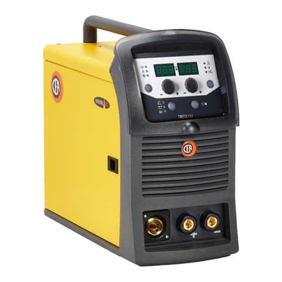
Page 6: Command And Control Units (Fig. A)
Command and control units (Fig. A) Pos. 1 Control panel. Pos. 2 Fast coupling straight polarity. Pos. 3 Fast coupling reverse polarity. Pos. 4 Centralised MIG-MAG torch connection. Pos. 5 Power supply switch. In the “O” position the welder is off. Pos. -
Page 7: Assembly Of Drive Roller
Assembly of drive roller Raise the idle roller (Pos. 1, Fig. B) by releasing the roller pressure device (Pos. 6, Fig. B). Raise the idle roller holding arm (Pos. 2, Fig. B) and proceed as follows: • The motor roller (Pos. 4, Fig. B) returns the type of wire and the diameter onto the two external faces. •... -
Page 8: Mig-Mag Welding Without Gas
FIG. C1 FIG. C2 MIG-MAG welding without GAS To begin MIG-MAG welding without gas, carry out the following tasks (with the machine switched off): 1 - Connecting the cables (Fig. D1-D2) 1) Screw the torch to the centralised connection on the front panel of the welding machine (Pos. 4, Fig. A). 2) Connect up the earthing system cable to the rapid coupling marked by a + (positive) symbol and then the relevant ground clamps to the piece being welded or to its support in an area free from rust, paint and grease. - Page 9 2 - Welding 1) Open the moving cover and fit a coil of wire with a core for welding without using gas. 2) Load the wire (see the “Loading the wire” paragraph). 3) Switch the welding machine on by moving the power supply switch to I (Pos. 5, Fig. A). 4) Carry out the following operations on the MIG-MAG torch: •...
-
Page 10: Aluminium Welding
Aluminium welding To weld with aluminum wire proceed as follows: • Replace the drive roller with the appropriate for aluminum wire. • Use a torch with a 3m cable and a carbon Teflon sheath. • Set the pressure between the drive rollers at the minimum, by turning the screw provided. •... -
Page 11: Electrode Welding (Mma)
FIG. F Electrode welding (MMA) Electrode welding is used to weld most metals (different types of steel, etc.) using coated rutilic and basic electrodes with diam- eters ranging from Ø 1.6 mm to Ø 3,2 mm. 1) Connecting the welding cables (Fig. G): Disconnect the machine from the mains power supply and connect the welding cables to the output terminals (Positive and Negative) of the welding machine, attaching them to the clamp and ground with the polarity specified for the type of electrode being used (Fig. -
Page 12: Maintenance
WELDING PARAMETERS Table 4 shows some general indications for the choice of electrode, based on the thickness of the parts to be welded. The val- ues of current to use are shown in the table with the respective electrodes for the welding of common steels and low-grade al- loys. -
Page 13: The Pointing Out Of Any Difficulties And Their Elimination
The pointing out of any difficulties and their elimination The supply line is attributed with the cause of the most common difficulties. In the case of breakdown, proceed as follows: 1) Check the value of the supply voltage. 2) Check that the power cable is perfectly connected to the plug and the supply switch. 3) Check that the power fuses are not burned out or loose. -
Page 14: Troubleshooting Table
Troubleshooting table WARNING: Any internal inspections or repairs are only to be done by qualified personnel! IMPORTANT: Remember to disconnect the mains power supply and wait for the internal capacitors to discharge (about 2 min- utes) before starting to check and repair the machine if necessary. Defect Solution The welding machine... -
Page 15: Electro Topographical Diagram
Electro topographical diagram Electro topographical diagram key •1 Circuito primario •2 Secondary circuit •3 Gas solenoid valve •4 Mains switch •5 Inductance •6 Front Rack panel •7 Fan motor •8 Drive motor •9 Polarity change •10 Earth terminal •11 Torch button •12 Primary rectifier •13 Secondary rectifier •14 SD memory connector •15 Power electronic board •16 Rack panel electronic board •17 Electrode torch •18 TIG torch •19 MIG-MAG torch •20 Main transformer •21 Secondary diodes thermostat •1 •2... -
Page 16: Meaning Of Graphic Symbols On Machine
Meaning of graphic symbols on machine SYMBOL DESCRIPTION Before using the equipment you should carefully read the instructions included in this manual Danger! Parts moving It is forbidden to use gloves Positive pole snap-in connector Negative pole snap-in connector Warning! Grounding protection Dangerous voltage System for use in environments with increased risk of electroshock... - Page 17 Reservedelliste LES NØYE ПЕРЕД НАЧАЛОМ РАБОТЫ Список запасных частей ВНИМАТЕЛЬНО ПРОЧТИТЕ ИНСТРУКЦИЮ CEA COSTRUZIONI ELETTROMECCANICHE ANNETTONI S.p.A. C.so E. Filiberto, 27 - 23900 Lecco - Italy Tel. +39.0341.22322 - Fax +39.0341.422646 Cas. Post. (P.O.BOX) 205 e-mail: cea@ceaweld.com - web: www.ceaweld.com...
- Page 18 Pos. TREO 181 Descrizione Description 352374 Visiera rack frontale Front rack transparent visorvisor 352373 Pannello frontale Front panel 468725 Adesivo logo "CEA" Logo "CEA" sticker 468185 Adesivo dinse Dinse sticker 403611 Attacco rapido Quick connection 239624 Cavo massa Ground cable...
- Page 19 Pos. TREO 181 Descrizione Description 352419 Coperchio pannello frontale Plastic front panel cover 434664 Maniglia Handle 465580 Staffa fissaggio maniglia Fixing bracket handle 435364 Interruttore principale Main switch 427895 Pressacavo Main cable gland 235960 Cavo alimentazione Main cable 485040 Tubo gas Gas hose 427866 Pressacavo...
- Page 20 Pos. TREO 181 Descrizione Description 377280A Scheda pannello rack completa di software Rack PCB with software 454150 Encoder Encoder 447974 Tastiera a membrana Membrane panel 423102 Dado encoder Encoder nut 438849 Manopola Knob...
- Page 21 Pos. TREO 181 Descrizione Description 450067 Scatola di protezione cambio di polarità Change polarity protection box 240561 Meccanismo di trascinamento con motoriduttore Wire feed mechanism with motorgear 404800 Basamento Steel base 241844 Mozzo bobina Ø200mm Spool holder Ø200mm 431333 Piedino in gomma Rubber foot...
- Page 22 Pos. TREO 181 Descrizione Description 413330 Flat cable Flat cable 413329 Cablaggio ausiliario Auxiliary electric harness 425933 Elettrovalvola gas Gas solenoid valve 377281 Scheda di potenza completa di software Power inverter PCB with software 486371 Ventilatore 235304 Cablaggio di potenza Power cable...
- Page 23 IT Complessivo meccanismo di trascinamento a 2 rulli EN Wire feeder unit assembly with 2 rolls Pos. Cod. Descrizione Description 444468 Motore 24V/40W 24V/40W Motor 602025 Seeger 10mm Seeger 10mm Tab. A Rullo Ø 30 mm Feed roll Ø 30 mm 487803 Vite di fissaggio Fixing screw...
- Page 24 IT Regolazione pressione rulli EN Rolls pressure IT Manutenzione trainafilo EN Wire feeder maintenance Frequenza di Interval of Parte Azione Item Action manutenzione maintenance Ogni 500 ore o Ispezione, pulizia o Every 500 hours or Inspect, clean or Rulli Rolls quando necessario sostituzione as needed...
- Page 25 IT Ordinazione dei pezzi di ricambio PT Requisição de peças sobressalentes Per la richiesta di pezzi di ricambio indicare chiaramente: Ao pedir as peças de substituição indique claramente: 1) Il numero di codice del particolare 1) O número de código da peça 2) Il tipo di impianto 2) O tipo de equipamento 3) La tensione e la frequenza che rileverete dalla targhetta...
- Page 26 Operator’s manual READ CAREFULLY CEA COSTRUZIONI ELETTROMECCANICHE ANNETTONI S.p.A. C.so E. Filiberto, 27 - 23900 Lecco - Italy Tel. +39.0341.22322 - Fax +39.0341.422646 Cas. Post. (P.O.BOX) 205 e-mail: cea@ceaweld.com - web: www.ceaweld.com...
- Page 27 ENGLISH Introduction Control panel Switching on the welding machine and initial screen Selection of welding programme MIG-MAG synergic MIG-MAG manual Loading of the wire MMA welding electrode TIG welding HOLD function Factory default Firmware update Error condition...
-
Page 28: Introduction
Introduction Il presente manuale contiene tutte le informazioni necessarie per This manual contains all the information necessary to make the best use of this control panel. Control panel ■ 1 - Parameter selection key - A This is used to select the following welding parameters: •... -
Page 29: Switching On The Welding Machine And Initial Screen
Switching on the welding machine and initial screen At the switching on of the welder (turn the switch, located on the back panel, at the position I), the control performs a short operation of machine check, and the panel display the initial screen (see the demonstrative figure), after which the operator can begin to work. Selection of welding programme Proceed in the following manner: 1) Press the key PRG (T2) to turn on the LED. -
Page 30: Mig-Mag Synergic
4) Press the key PRG (T2) to turn off the LED and confirm the selection. MIG-MAG synergic Proceed in the following manner: 1) Start the welder by rotating the switch, located on the back panel, at the position I. 2) Select the MIG-MAG welding process by using the key T1. 3) Press the key PRG (T2) to turn on the LED. -
Page 31: Mig-Mag Manual
7) Key T4 allows you to select: • Arc length adjustment ( • Welding voltage ( ). • Electronic inductance ( MIG-MAG manual Proceed in the following manner: 1) Start the welder by rotating the switch, located on the back panel, at the position I. 2) Select the MIG-MAG welding process by using the key T1. -
Page 32: Loading Of The Wire
7) Key T4 allows you to select: • Welding voltage ( ). • Electronic inductance ( Loading of the wire In the MIG-MAG welding processes, with the welder in operation, it is possible to load the wire inside the torch, following this simple procedure: •... -
Page 33: Tig Welding
TIG welding Proceed in the following manner: 1) Start the welder by rotating the switch, located on the back panel, at the position I. 2) Select the TIG welding process using the key T1. 3) Turn the knob E1 to adjust and view the TIG welding current on the display D1. HOLD function This function will then start automatically at the end of each welding operation, and is signalled to the operator by the HOLD LED light turning on. -
Page 34: Factory Default
Factory default WARNING: If carried out, this operation results in complete resetting of all editable parameters to the factory settings. To carry out the reset of the settings / parameters, proceed in the following manner: 1) Press the key PRG (light on). 2) Rotate the E1 knob until both the displays read FAC no (see figure). -
Page 35: Firmware Update
Firmware update ATTENTION: Before carrying out any inspection of the inside of the generator, disconnect the system from the supply. The welding machine can be updated using an SD card. Proceed as follows: • Turn off the welding machine by moving the main switch to the position “O”. •... -
Page 36: Error Condition
Error condition This paragraph describes the error conditions that may arise on the welding machine, the codes and messages shown on both opera- tor interface displays, and the diagnoses for attempting to correct and resolve them. In an “error condition” the operator’s interface uses both displays to display: ▪ ERROR CONDITION display ▪ ERROR DESCRIPTION display Error condition... - Page 37 CEA COSTRUZIONI ELETTROMECCANICHE ANNETTONI S.p.A. C.so E. Filiberto, 27 - 23900 LECCO - ITALY Cas. Post. (P.O. BOX) 205 Tel. +39 0341 22322 - Fax +39 0341 422646 cea@ceaweld.com www.ceaweld.com...
Need help?
Do you have a question about the TREO 181 MIG/MAG and is the answer not in the manual?
Questions and answers