Table of Contents
Advertisement
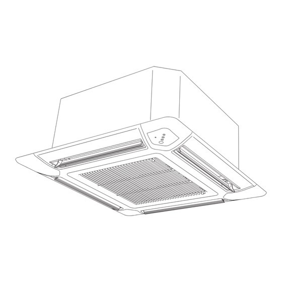
AIR CONDITIONER
INDOOR UNIT
Compact Cassette Type
RICH07AVFJ
RICH09AVFJ
RICH12AVFJ
RICH18AVFJ
INSTALLATION MANUAL
For authorized service personnel only.
Contents
1. SAFETY PRECAUTIONS ................................................ 2
1.1. IMPORTANT! Please read before starting ............. 2
1.2. SPECIAL PRECAUTIONS ..................................... 2
2. ABOUT THE UNIT ........................................................... 3
2.1. Precautions for using the R410A refrigerant .......... 3
2.2. Special tools for R410A .......................................... 3
2.3. For authorized service personnel only. .................. 3
2.4. Accessories ............................................................ 4
2.5. Optional parts ......................................................... 4
2.6. Decoration panel accessories ................................ 4
3. GENERAL ....................................................................... 5
3.1. Type of copper pipe and insulation material ........... 5
3.2. Additional materials required for installation ........... 5
3.3. Operating range ..................................................... 5
4. ELECTRICAL REQUIREMENT ....................................... 5
5. SELECTING THE MOUNTING POSITION ..................... 5
5.1. Discharge direction setting ..................................... 6
6. INSTALLATION WORK ................................................... 6
6.1. Installation dimensions ........................................... 6
6.2. Pipe installation ...................................................... 8
6.3. Installing the coupler heat insulation .................... 10
9374318438-05_IM.indb 1
7. ELECTRICAL WIRING .................................................. 11
7.1. Wiring system diagram ......................................... 11
7.2. Connection cable preparation .............................. 12
7.3. Connection of wiring ............................................. 12
8. DECORATION PANEL INSTALLATION ........................ 12
8.1. Removing the intake grille .................................... 12
8.2. Installing panel to unit .......................................... 12
8.3. Attaching the intake grille ..................................... 13
9. REMOTE CONTROLLER SETTING ............................. 13
9.1. Installing the remote controller ............................. 14
9.2. Setting the dip switches ....................................... 15
9.3. Function setting .................................................... 15
9.4. Test run................................................................. 17
10. SPECIAL INSTALLATION METHODS ........................ 18
11. OPTIONAL KIT INSTALLATION (OPTION) ................. 18
12. ERROR CODES .......................................................... 19
13. CUSTOMER GUIDANCE ............................................ 20
9/10/2010 11:10:04 AM
Advertisement
Table of Contents

Related Manuals for Rheem RICH07AVFJ


Summary of Contents for Rheem RICH07AVFJ
-
Page 1: Table Of Contents
AIR CONDITIONER INDOOR UNIT Compact Cassette Type RICH07AVFJ RICH09AVFJ RICH12AVFJ RICH18AVFJ INSTALLATION MANUAL For authorized service personnel only. Contents 1. SAFETY PRECAUTIONS ..........2 7. ELECTRICAL WIRING ..........11 1.1. IMPORTANT! Please read before starting ..... 2 7.1. Wiring system diagram ......... 11 1.2. -
Page 2: Safety Precautions
When Installing... 1. SAFETY PRECAUTIONS ...In a Ceiling or Wall Make sure the ceiling/wall is strong enough to hold the unit’s 1.1. IMPORTANT! Please read before starting weight. It may be necessary to construct a strong wood or metal frame to provide added support. This air conditioning system meets strict safety and operating ...In a Room standards. -
Page 3: About The Unit
2. ABOUT THE UNIT WARNING Do not use the existing (for R22) piping and flare nuts. 2.1. Precautions for using R410A refrigerant • If the existing materials are used, the pressure inside the refrigerant cycle will rise and cause failure, injury, The basic installation work procedures are the same etc. -
Page 4: Accessories
Wired Remote 2.4. Accessories Controller WARNING Remote Controller For connecting the Cable remote controller For installation purposes, be sure to use the parts supplied by the manufacturer or other prescribed parts. The use of non-prescribed parts can cause serious accidents such as the unit to fall, water leak- age, electric shock, or ¿... -
Page 5: General
3. GENERAL 4. ELECTRICAL REQUIREMENT This INSTALLATION MANUAL brieÀ y outlines where and Always make the air conditioner power supply a special how to install the air conditioning system. Please read over branch circuit and provide a special switch and receptacle. Do the entire set of instructions for the indoor and outdoor units not extend the power cable. -
Page 6: Discharge Direction Setting
CAUTION 5.1. Discharge direction setting Install the indoor unit, outdoor unit, power supply • The discharge direction can be selected as shown below. cable, and remote control cable at least 40 in. 100 (3-15/16) or more* (1 m) away from a television or radio receivers. The purpose of this is to prevent TV reception interference or radio noise. - Page 7 6.1.1. Installing body Special nut A Unit: mm(in.) Cealing openings and hanging bolt installation diagram After installing the Hook body, tighten the nuts. Special nut B WARNING When fastening the hangers, make the bolt positions 30 (1-3/16) Hanging bolt uniform. or more Unit: mm (in.) 530 (20-7/8) (Hanging bolt position)
-
Page 8: Pipe Installation
Unit: mm (in.) 300 (11-13/16) Downward gradient Attach hose band 1/100 or more (Accessories) Install the knob facing upward 3/4 in. (O.D. 1-1/16 in) (Local arrangement) Locally installed Attach drain hose PCV pipe Attach band Attach drain hose (Accessories) 1 .5m~2m Hanging fitting (5' - 6' 6") Attach heat insulation... - Page 9 6.2.1. Selecting the pipe material CAUTION Do not use mineral oil on À ared part. Prevent mineral CAUTION oil from getting into the system as this would reduce Do not use existing pipes. the lifetime of the units. While brazing the pipes, be sure to purge with Use pipes that have clean external and internal sides without nitrogen gas.
-
Page 10: Installing The Coupler Heat Insulation
6.2.4. Bending pipes 6.2.5. Connection pipes • If pipes are shaped by hand, be careful not to collapse Indoor unit them. (1) Remove the caps and plugs from the pipes. • Do not bend the pipes in an angle more than 90°. (2) Centering the pipe against port on the indoor unit, turn the •... -
Page 11: Electrical Wiring
7. ELECTRICAL WIRING 7.1. Wiring system diagram Connection cable to outdoor unit or BRANCH BOX WARNING Before starting work, check that power is not being supplied to the indoor unit and outdoor unit. Power line Match the terminal board numbers and connection cord colors with those of outdoor unit or branch box unit. -
Page 12: Connection Cable Preparation
Connection cable Binder CAUTION (to OUTDOOR UNIT or BRANCH BOX) Be sure to refer to the above diagram for do correct ¿ eld wiring. Wrong wiring causes malfunction of the unit. Check local electrical rules and also any speci¿ c wiring instructions or limitation. -
Page 13: Attaching The Intake Grille
8.3. Attach the intake grille T h e i n s t a l l a t i o n i s t h e r e v e r s e o f “ R E M O V I N G T H E INTAKE GRILLE”. -
Page 14: Installing The Remote Controller
9.1. Installing the remote controller 120 (4-23/32) (21/32) Open the operation panel on the front of the remote control- ler, remove the 2 screws indicated in the following ¿ gure, and then remove the front case of the remote controller. When installing the remote controller, remove the connector from the front case. -
Page 15: Setting The Dip Switches
9.2. Setting the dip switches 9.3. Function setting Set the remote controller DIP switches. This procedure changes the function settings used to control [Example] the indoor unit according to the installation conditions. Incor- rect settings can cause the indoor unit to malfunction. This Front case (back side) procedure should be performed by authorized installation or service personnel only. - Page 16 (4) Press the SET TEMP. buttons ( ) to select the set- (3) Outlet directions ting value. Select the setting values in the table below for using a The display À ashes as shown to the right during setting 3-way outlet. value selection.
-
Page 17: Test Run
Room temperature is controlled by the indoor unit SETTING THE ROOM TEMPERATURE temperature sensor. DETECTION LOCATION * If setting value is “01”: The detection location of the room temperature can be se- Room temperature is controlled by either indoor unit lected from the following 2 examples. -
Page 18: Special Installation Methods
(3) Press the start/stop button to stop the test run. 10. SPECIAL INSTALLATION METHODS If “C0” appears in the unit number display, there is a remote controller error. Refer to the installation manual included with CAUTION the remote controller. When setting DIP switches, do not touch any other parts on Unit number Error code Content... -
Page 19: Error Codes
12. ERROR CODES If you use a wired type remote control, error codes will appear on the remote control display. If you use a wireless remote control, the lamp on the photodetector unit will output error codes by way of blinking patterns. See the lamp blinking patterns and error codes in the table below. -
Page 20: Customer Guidance
[Troubleshooting at the remote control LCD] 13. CUSTOMER GUIDANCE This is possible only on the wired remote control. [Self-diagnosis] Explain the following to the customer in accordance with the If an error occurs, the following display will be shown. operating manual: (“Er”...
Need help?
Do you have a question about the RICH07AVFJ and is the answer not in the manual?
Questions and answers