Table of Contents
Advertisement
INSTALLATION INSTRUCTIONS
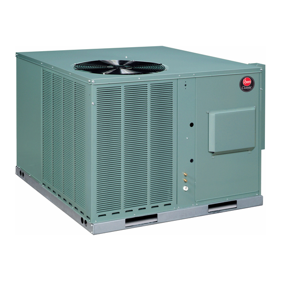
PACKAGE GAS ELECTRIC
FEATURING EARTH-FRIENDLY R-410A REFRIGERANT
RRNL- 13 SEER (2-5 TONS)
RRPL- 14 SEER (2-5 TONS)
RRRL- UP TO 16 SEER (2-5 TONS)
Seasonal Energy Efficiency Ratio (SEER)
RRNL
RRPL
13.0
14.0
—
10.6
Uses least energy
Annual Fuel Utilization Efficiency -
THIS MODEL
80.0%
MID
78%
82%
88%
ISO 9001:2000
RRRL
16.0
©
16.05
AFUE
HIGH
97%
(14 SEER &
ABOVE)
U.L. recognized fuel gas and CO (carbon monoxide) detectors are recommended in all
applications, and their installation should be in accordance with the manufacturer's
recommendations and/or local laws, rules, regulations, or customs.
r e f r i g e r a n t
92-21916-30-04
SUPERSEDES 92-21916-30-03
Advertisement
Table of Contents

Summarization of Contents
SAFETY INFORMATION
General Safety Warnings
General safety warnings applicable to unit installation and operation.
R-410A System Pressure Caution
Caution regarding R-410A systems operating at higher pressures.
INTRODUCTION AND SPECIFICATIONS
II. INTRODUCTION
Introduces the installation and operating instructions for the unit.
III. CHECKING PRODUCT RECEIVED
Instructions for inspecting the unit for damage and verifying its contents upon receipt.
IV. SPECIFICATIONS - GENERAL
Provides general specifications for the combination gas heating/electric cooling unit.
IV. SPECIFICATIONS - MAJOR COMPONENTS
Lists and describes the main components of the unit.
COMFORT ALERT SYSTEM
Quick Reference Guide For R-410A
Quick reference points for servicing R-410A systems.
Evaporator Coil / TXV
Information on the evaporator coil and thermostatic expansion valve for R-410A.
Tools Required For R-410A Models
Lists necessary tools for installation and servicing of R-410A models.
D. COMFORT ALERT™ SYSTEM
Describes the Comfort Alert system for troubleshooting AC system failures.
UNIT DIMENSIONS AND CLEARANCES
V. UNIT DIMENSIONS FOR CLEARANCES
Provides unit dimensions and clearance requirements for installation.
FIGURE 4: Unit Dimensions
Illustrates the unit's external dimensions and key features for clearances.
INSTALLATION GUIDELINES
VI. INSTALLATION - GENERAL CONSIDERATIONS
General considerations and pre-installation check-points for unit installation.
VI. INSTALLATION - OUTSIDE INSTALLATION
Guidelines for installing the unit outdoors, including slab installation.
VI. INSTALLATION - ATTACHING HOODS
Instructions for attaching exhaust and combustion air inlet hoods to the unit.
VI. INSTALLATION - COVER PANEL PROCEDURE
Steps for converting cover panels for different installation configurations.
GAS, DRAINAGE, AND PIPING
VII. GAS SUPPLY, CONDENSATE DRAIN AND PIPING - GAS CONNECTION
Instructions for connecting the unit's gas supply line and related components.
VII. GAS SUPPLY, CONDENSATE DRAIN AND PIPING - LP CONVERSION
Instructions and warnings for converting the unit to use LP gas.
VII. GAS SUPPLY, CONDENSATE DRAIN AND PIPING - CONDENSATE DRAIN
Information and warnings regarding the condensate drain system.
WIRING AND CONTROL SYSTEMS
VIII. WIRING - POWER SUPPLY
Safety warning and instructions for connecting the unit's power supply.
VIII. WIRING - HOOK-UP DIAGRAM
Instructions for wiring the unit, referring to hook-up diagrams.
VIII. WIRING - THERMOSTAT COMPATIBILITY
Guidelines for selecting and wiring a compatible room thermostat.
FURNACE OPERATION AND MAINTENANCE
IX. FURNACE SECTION CONTROLS - OPERATING SEQUENCE
Describes the step-by-step sequence of furnace operation and ignition.
IX. FURNACE SECTION CONTROLS - OPERATING INSTRUCTIONS
Instructions for starting and operating the furnace, including safety warnings.
X. SYSTEM OPERATING INFORMATION - ADVISE THE CUSTOMER
Tips for the customer to keep the system operating efficiently.
X. SYSTEM OPERATING INFORMATION - FURNACE MAINTENANCE
Recommendations and procedures for annual inspection and cleaning of the furnace section.
UNIT MAINTENANCE
COOLING SECTION MAINTENANCE
Recommendations for inspecting and cleaning the cooling section components.
Cooling Section Cleaning Procedures
Detailed procedures for cleaning the evaporator coil and condenser coil.
G. BLOWER MOTOR SPEED ADJUSTMENTS
Instructions for adjusting blower motor speeds on PSC and X-13 motors.
ECM BLOWER MOTORS AND SETTINGS
XI. UNITS WITH ECM BLOWER MOTORS (RRRL-B MODELS ONLY)
Information specific to units equipped with ECM blower motors.
A. ECM MOTOR INTERFACE CONTROL AND SETTINGS
Explains the ECM motor interface board, DIP switch functions, and settings.
C. USING THE ON-BOARD LED TO DETERMINE BLOWER CFM
How to use the on-board LED to determine blower CFM.
E. COOLING AIRFLOW ADJUSTMENTS
How to adjust cooling airflow using DIP switches 3 & 4.
GENERAL DATA TABLES
XII. GENERAL DATA - RRNL- MODELS
Provides detailed specifications and performance data for RRNL models.
GENERAL DATA - RRNL-B MODELS
Provides detailed specifications for RRNL-B model series.
GENERAL DATA - RRPL- MODELS
Provides detailed specifications and performance data for RRPL models.
ELECTRICAL AND AIRFLOW DATA
XIII. MISCELLANEOUS DATA - ELECTRICAL DATA - RRRL SERIES
Electrical data tables for RRRL series units, covering compressor, condenser, and evaporator fan.
XIII. MISCELLANEOUS DATA - ELECTRICAL DATA - RRPL SERIES
Electrical data tables for RRPL series units, covering compressor, condenser, and evaporator fan.
XIV. AIRFLOW PERFORMANCE DATA
Provides indoor airflow performance data for 2-5 Ton Package Gas Electric Units.
WIRING DIAGRAMS AND CHARTS
XV. WIRING DIAGRAMS
Provides wiring diagrams for the unit's electrical connections.
XVI. REFRIGERANT CHARGE CHARTS
System charge charts for various cooling tonnages with R-410A refrigerant.
TROUBLESHOOTING AND DIAGNOSTICS
XVII. TROUBLESHOOTING
Troubleshooting guide for common unit issues.
Furnace Troubleshooting Guide
Furnace troubleshooting guide presented as a flowchart.
XVIII. COMFORT ALERT DIAGNOSTIC CHART
Diagnostic chart for the Comfort Alert system (Single Phase Unit).


Need help?
Do you have a question about the RRPL-B030JK08E and is the answer not in the manual?
Questions and answers