Table of Contents
Advertisement
Advertisement
Table of Contents

Related Manuals for Nitgen NAC-2500 Plus


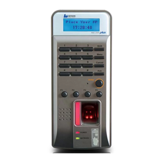
Summary of Contents for Nitgen NAC-2500 Plus
- Page 1 NAC-2500 Terminal Installation Guide...
- Page 2 Reproduction of part or all of the contents in any form is prohibited other than in accordance with the permissions. Product specification can be changed and upgraded to improve functionality without prior notice. NITGEN, NITGEN logo are registered trademark of NITGEN. To Contact Us Tel. +82-80-060-1600 (Toll Free) Fax.
-
Page 3: Table Of Contents
Table of Contents 1. Before Installation 1.1 To install ----------------------------------------------------------- 4 1.2 Product package ------------------------------------------------ 4 2. Installation Environment ---------------------------------------------- 6 3. System Configuration 3.1 Network mode ----------------------------------------------------- 7 3.2 Standalone mode ------------------------------------------------- 8 4. Installation 4.1 Fastening the auxiliary plate ---------------------------------- 4.2 Attaching other devices except the terminal -------------- 11 4.3 Connecting external cables ----------------------------------- 12 4.4 Fastening the terminal ----------------------------------------- 16... -
Page 4: Before Installation
1. Before Installation 1.1 To install Please follow the installation guide because the performance can be decreased if the product is installed incorrectly. 1.2 Product package Product Pictures Terminal Access Controller Adapter Supplying power for the terminal Power cord Rear case Fastening the terminal - 4 -... - Page 5 Bolt Fastening the terminal Fastening the rear case Housing Connecting door cable Receptacle & cable S/W CD - 5 -...
-
Page 6: Installation Environment
2. Installation Environment Please keep in mind the following conditions when you install the product. You might need to obtain the user's consent if necessary. ① This product is originally designed to install indoors. If you have to install it outdoors, however, do not expose the terminal to direct sunlight, snow or rain. -
Page 7: System Configuration
3. System Configuration 3.1 Network mode Terminals are connected by network and it can be remote control. Server PC Client PC Network(TCP/IP) Terminal Lock Door Open S/W Figure 3.1 Network Block Diagram - 7 -... -
Page 8: Standalone Mode
3.2 Standalone mode One terminal is used independently. All settings such as user registration, deletion, and access control are performed in the terminal alone. Locking Device Interphone Door Open S/W Figure 3.2 Terminal Block Diagram - 8 -... -
Page 9: Installation
4. Installation ☞ The overall installation procedure is as follows: ① Fasten the bracket ② Attach other devices except terminal(locking device, interphone, etc.) ③ Connect the external cables ④ Fasten the terminal 4.1 Fastening the auxiliary plate ① Decide where you want to install the product, and cut the rear case as shown Figure 4.1 to make the hole for wiring. - Page 10 ② Align the bracket with the hole for wiring as shown Figure 4.2, and fasten it with 6 bolts supported in the packet. Figure 4.2 Fastening rear case - 10 -...
-
Page 11: Attaching Other Devices Except The Terminal
4.2 Attaching other devices except terminal ☞ You can attach the following devices. Refer to the specifications of each device for more information on installation. ① Locking device ② Door Open button ■ Types of installable locking devices and specifications Type Specifications Remarks... - Page 12 4.3.1 Connecting the door control cable (Main board J2) ■ Specifications of the cable and material Housing Receptacle Cable 5264-06 5263PBT UL Cable, 24~28AWG ☞ Connection Note ① Pay attention to terminal numbers when connecting the cable to the connector. ②...
- Page 13 ■ How to connect cables by types of locking devices EM Lock Deadbolt Strike Contact_A Power(Fail Secure) Common Contact_B Power(Fail Safe) Door Monitor Door Monitoring Signal Door Open Door Open Button Deadbolt/Strike/Electronic Magnetic-Lock Fail Feature Fail Door Door Secure Safe Type Monitoring Open Type...
- Page 14 Auto Door Feature Normal Normal Door Door Open Close Monitoring Open Open button Open Door Open button button Monitor Door Monitoring (12/24V) CONTACT_B Contact COMMON Contact Contact CONTACT_A Contact *The relay board [JP1]=>Open - 14 -...
- Page 15 4.3.2 Connecting the network cable (Network board J3) ① Connect network lines as follows (pay attention to PIN numbers): Schematic Housing Cable PIN No Feature RJ45, 8PIN 4.3.3 Connecting the power cable Connect 12V adapter to Relay Board J4. Connect 5V adapter ro Main Board J3 'NOTICE : When you connect extend cable, make sure the polarity(+, -) are correct' 4.3.4 Wiegand output (Main board J5)
- Page 16 4.3.5 RS-485 (Main board J1) * If the device needs a termimal resistance, connect J18. J1 Connection PIN Number Function TRX- TRX+ 4.3.6 Wiegand input (Main board J9) * Wiegand input cannot be used with RF module. J9 Conncetion PIN Number Function +5VDC Wiegand 0...
- Page 17 4.3.7 Normal RF Module Option(J9): HID, MIFARE, EM - JP2: 5VA - R74,R75: 0Ω - R72,R73: Open - 17 -...
- Page 18 4.3.8 SOC RF Module Option (J9) - JP2: 3VA - R74,R75: Open - R72,R73: 0Ω - 18 -...
-
Page 19: Fastening The Terminal
4.4 Fasten the terminal ① Assemble the terminal with the rear case as shown in Figure 4.3. Figure 4.3 Assebling with rear case ② Screwing the terminal as shown in Figure 4.4 with the 4 terminal screws supported in the package. Figure 4.4 Screwing the terminal - 19 -... - Page 20 ③ If you did all the procedures described, the termimal installation is completed as shown in Figure 4.5. Figure 4.5 Teminal after the installaion - 20 -...
-
Page 21: Check After Installation
For more information, please refer to "NAC-2500 Terminal User Manual" and "Access Manager User Manual ". ① When power is supplied, the initial screen with NITGEN logo will appear. ② Press the menu button to choose System Option > Terminal Mode and check if the terminal is in SO mode.
Need help?
Do you have a question about the NAC-2500 Plus and is the answer not in the manual?
Questions and answers