Table of Contents
Advertisement
Quick Links
eNBioAccess-T2 User Guide
© Copyright 2013, NITGEN Co., Ltd.
All rights reserved.
It is strictly prohibited to compile, duplicate or publish part. Or whole of this manual prior written consent of NITGEN.
The specification of this product may be changed without prior notice to improve its functionality.
The logo of NITGEN&COMPANY is a registered trademark of NITGEN Co., Ltd.
Other names or trademarks are registered trademarks of their respective owners.
12F, Daemyung Valeon bldg., 127, Beobwon-ro,
Songpa-gu, Seoul, Korea (05836)
Tel : 02-6488-3232 , Fax : 02-6488-3099,
E-Mail :customer@nitgen.com
http://www.nitgen.com
Version eng-1.70
`
Advertisement
Table of Contents

Related Manuals for Nitgen eNBioAccess-T2


Summary of Contents for Nitgen eNBioAccess-T2
- Page 1 © Copyright 2013, NITGEN Co., Ltd. All rights reserved. It is strictly prohibited to compile, duplicate or publish part. Or whole of this manual prior written consent of NITGEN. The specification of this product may be changed without prior notice to improve its functionality.
- Page 2 User Guide <Revison History > Version Date Description Firmware Version 1.00 2016-07-15 Initial Release 1000-01 1.10 2016-08-17 Modified the description for icon information. 1000-02 1.20 2016-09-01 EMC Open function Deletion 1000-04 LOCK1/LOCK2 Result Output Menu Deletion 1.30 2016-09-19 User Logo Description Addition 1000-05 Terminal <->...
- Page 3 User Guide <Glossary > Administrator (Admin) - The administrator can access the terminal menu mode. He/she has the authority to add/modify/delete terminal users and to change the operating environment by changing settings. - If there is no registered administrator in the terminal, anybody can access to the terminal menu and change settings.
-
Page 4: Table Of Contents
User Guide Table of Contents Before Getting Started ................. 6 1.1. Safety Notes ......................6 1.2. Product Details ....................7 1.2.1. FRONT ...................... 7 1.2.2. REAR ......................8 1.2.3. Input / Output ..................... 9 1.3. Screen information during operation .............. 12 1.3.1. -
Page 5: Enbioaccess-T2 User Guide
User Guide 3.6.1. Menu Configuration .................. 39 3.6.2. ADD ......................39 3.6.3. AUTO ADD ....................41 3.6.4. MODIFY ....................42 3.6.5. DELETE ....................43 3.6.6. DELETE ALL ....................43 3.7. Network Menu ....................44 3.7.1. Menu Configuration .................. 44 3.7.2. -
Page 6: Before Getting Started
User Guide 1. Before Getting Started 1.1. Safety Notes Warning Do not operate the terminal with wet hands, and pay attention not to let any Keep the terminal away liquid such as water enter from inflammables. inside the terminal. -
Page 7: Product Details
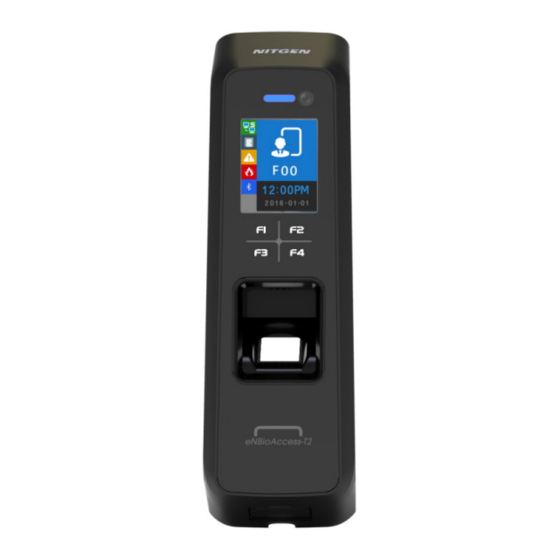
User Guide 1.2. Product Details 1.2.1. FRONT BLE embedded State LED Camera Function KEY (F1~F4) Speaker Fingerprint Sensor Card Sensor (EM/SC/HID) USB assist device (UDL10) connection 12F, Daemyung Valeon bldg., 127, Beobwon-ro, Songpa-gu, Seoul, Korea (05836) Tel : 02-6488-3232 , Fax : 02-6488-3099, E-Mail :customer@nitgen.com... -
Page 8: Rear
User Guide 1.2.2. REAR Fixed bracket Cable harness 12F, Daemyung Valeon bldg., 127, Beobwon-ro, Songpa-gu, Seoul, Korea (05836) Tel : 02-6488-3232 , Fax : 02-6488-3099, E-Mail :customer@nitgen.com http://www.nitgen.com... -
Page 9: Input / Output
User Guide 1.2.3. Input / Output Cable & Connector 1 . 2 . 3 . 1 . 12F, Daemyung Valeon bldg., 127, Beobwon-ro, Songpa-gu, Seoul, Korea (05836) Tel : 02-6488-3232 , Fax : 02-6488-3099, E-Mail :customer@nitgen.com http://www.nitgen.com... - Page 10 User Guide Pin Details 1 . 2 . 3 . 2 . Line color Label Explanation IN/OUT Note number (Line name) ORANGE Inside open Connect to Exit button YELLOW DoorMonitor0 Sense door state(DM0) GREEN DoorMonitor1 Sense door state(DM1) BLUE...
- Page 11 User Guide e rminal <- > LC015B wiring 1 . 2 . 3 . 4 . Category T2 terminal (Line name) LC015B RS485A R4A (green) 485A RS485B R4B (blue) 485B ground connection GND (black) DOOR MONITOR IN1(If this pin is not used, connect to GND Pin.)
-
Page 12: Screen Information During Operation
User Guide 1.3. Screen information during operation 1.3.1. Initial Screen When powering on at first, the screen is displayed as follow. State icon Operation Mode TNA Mode Date and Time 1.3.2. Icons NONE : No use network : LAN line is disconnected. -
Page 13: Function Key
User Guide 1.3.3. Function KEY Icon Meaning Function Key Explanation Move cursor up. DOWN Move cursor down. LEFT Move cursor to left. F2 long Move to upper menu. RIGHT Move cursor to right. F4 long or ENTER Move to submenu. - Page 14 User Guide Menu of Initial Screen Authentication succeess Authentication failure Waiting for Card Input Waiting for Fingerprint Input Waiting for Admin App registration 12F, Daemyung Valeon bldg., 127, Beobwon-ro, Songpa-gu, Seoul, Korea (05836) Tel : 02-6488-3232 , Fax : 02-6488-3099, E-Mail :customer@nitgen.com...
-
Page 15: Led Information During Operation
User Guide 1.4. LED information during operation Operating state Remark Normal Alarm ON or Flash ON (Maintain during authentication time) Authentication Failure Normal GREEN ON (Maintain during authentication time) Authentication Success BLUE Terminal Normal(alive) Flash at intervals of 5 seconds... -
Page 16: How To Register And Enter The Correct Fingerprint
User Guide 1.7. How to register and enter the correct fingerprint Correct fingerprint input method Enter your fingerprint as if you take a thumbprint by using your forefinger if possible. The fingerprint cannot be correctly registered and entered only by your fingertips. -
Page 17: Product Descriptions
User Guide 2. Product Descriptions 2.1. Product Features BLE is equipped. Door Control with smartphone is possible at close range. It is equipped with Color Camera, and it saves the visitor’s video when authentication succeeds or fails. Optional, Available to use as RF(125kHz), Smart Card(13.56MHz), HID Reader... -
Page 18: Diagram
User Guide 2.2. Diagram 2.2.1. Single Type (Door Lock) Close BLE 2.4G Lock control Open Mobile App Door Lock 2.2.2. Single Type (Lock Controller) Close RS485 BLE 2.4G Open Mobile App Lock Controller (LC010, LC015) 2.2.3. Dummy Type (MCP040) -
Page 19: Network Type (Door Lock)
User Guide 2.2.4. Network Type (Door Lock) Close BLE 2.4G Lock Control Open Mobile App Ethernet Door Lock Ethernet Internet Server 2.2.5. Network Type (Lock Controller) Close RS485 BLE 2.4G Open Mobile App Lock Controller (LC010, LC015) Ethernet Ethernet... -
Page 20: Product Specification
User Guide 2.3. Product Specification Category Spec 32Bit RISC CPU(400MHz) MEMORY 64M DDR RAM, 32M NOR,128M NAND Camera VGA, F2.8, View angle 61 degree 1.77’’ Color LCD Fingerprint Sensor Optical / 500 DPI Authentication Method Fingerprint, RF Card, Mobile Card Authentication Speed 1:N <... -
Page 21: Environment Setting
User Guide 3. Environment Setting 3.1. Checkpoints before Environment Setting 3.1.1. Menu Press F4 long until the menu screen is displayed. It is available to enter the menu without authentication because the manager doesn’t register when shipping the product. -
Page 22: How To Access The Menu Without Administrator Authentication
User Guide 3.1.3. How to access the menu without administrator authentication This is the method to enter the Menu in exceptional cases such as losing your administrator card that is registered in the terminal or inability to make a fingerprint authentication because of absence of administrator. -
Page 23: Default Setting
User Guide 3.1.5. Default Setting Category Default setting MENU > NETWORK MENU > NETWORK > USE > AUTH MODE MENU > NETWORK > USE > TEMINAL ID MENU > NETWORK > USE > TEMINAL > STATIC MENU > NETWORK > USE > TEMINAL > STATIC >... -
Page 24: Setting Guide For Network Configuration
User Guide MENU > EXT DEVICE > WIEGAND > WIE-OUTPUT> 26 BIT or 34 BIT > SITE CODE > SEND INFO 3.1.6. Setting guide for Network Configuration Single Type (Door Lock=STRIKE) 3 . 1 . 6 . 1 . - Page 25 User Guide Dummy Type (RS485=MCP040) 3 . 1 . 6 . 5 . Menu Position Possible setting MENU>NETWORK> (Use : When only downloading DB) MENU>EXT DEVICE>DOORLOCK>LOCK1>TYPE NONE MENU>EXT DEVICE>DOORLOCK>DM0 NONE MENU>EXT DEVICE>DOORLOCK>LOCK2>TYPE NONE MENU>EXT DEVICE>DOORLOCK>DM1 NONE MENU>EXT DEVICE>RS485>TYPE MCP040 MENU>EXT DEVICE>RS485>DEV ID...
- Page 26 User Guide MENU>NETWORK> MENU>NETWORK>USE>AUTH MODE MENU>NETWORK>USE>TERMINAL ID 0001 MENU>NETWORK>USE>TERMINAL>STATIC IP:192.168.0.3 SN:255.255.255.0 GW:192.168.0.1 MENU>NETWORK>USE>SERVER IP:192.168.0.2 PORT:7332 MENU>EXT DEVICE>DOORLOCK>LOCK1>TYPE NONE MENU>EXT DEVICE>DOORLOCK>DM0 NONE MENU>EXT DEVICE>DOORLOCK>LOCK2>TYPE NONE MENU>EXT DEVICE>DOORLOCK>DM1 NONE MENU>EXT DEVICE>RS485>TYPE LC010 MENU>EXT DEVICE>RS485>DEV ID Network Type (Lock Controller=LC015) 3 . 1 . 6 . 9 .
-
Page 27: How To Register The Terminal In Admin App
User Guide 3.2. How to register the terminal in Admin App 3.2.1. Install iAccess M Plus iAccess M Plus is the smartphone App for administrator controlling device via BLE. You can download and install it from Play Store. For more details, please refer iAccess M Plus installation guide. -
Page 28: Terminal Login Admin App
User Guide 3.2.4. Terminal login Admin App When the terminal is BLE REDAY, press ADD on iAccess M Plus App and select the terminal. If you know the administrator's ID and password, then click OK to log in. If you do not know the administrator’s ID &... -
Page 29: Access Device With Admin App
User Guide 3.3. Access Device with Admin App If the terminal registration on Admin App is successful, the list is displayed as follows. When pressing View, the pop-up window is displayed to connect the terminal. If the administrator is registered in the terminal, it requires the administrator authentication. -
Page 30: Access And Registration Between Acm Pro And Terminal
User Guide 3.4. Access and Registration between ACM Pro and terminal 3.4.1. Install ACM Pro When shipping the product, it installs ACM Pro Program in PC from the provided CD. For installation guide, please refer the relevant document. 3.4.2. Execute ACM Pro If executing the program, login screen is displayed. -
Page 31: Set In Terminal
User Guide Set in terminal 3.4.3. In order to connect the terminal to the server, set to the network mode and set the information. Move to MENU > NETWORK > USE > TERMINAL and check whether lower information is correct or not. -
Page 32: Register The Terminal In Acm Pro
User Guide 3.4.5. Register the terminal in ACM Pro Select the unregistered terminal and press Registration button to activate the screen below. Enter device name and explanation to press OK. If the registration is successful, the screen is displayed as follow. -
Page 33: Menu Configuration
User Guide 3.5. Menu Configuration The whole menu is composed of seven, and main characteristics are as follows. Menu Submenu1 Submenu2 Submenu3 USER USER USER ADMIN INPUT ID *Authentication Type Card MCARD *Authentication Condition MCARD is OR condition only. - Page 34 User Guide NETWORK NO USE Operate in single mode AUTH MODE Server/Terminal Terminal/Server Server Terminal TERMINAL ID TERMINAL ID STATIC STATIC DHCP Subnet mask Gateway DHCP SERVER SERVER Port No OPTION ATTEND TYPE NONE M1 F1~F2 M2 F1~F4 M3 F1~F49...
- Page 35 User Guide SETTING YYYYMMDD-hhmmss FP SENSOR 1:1 LEVEL (1~9) DEVICE 1:N LEVEL (5~9) LFD LEVEL NONE MIDDLE HIGH AUTH TIME BEEP VOICE BLE READY TAMPER NO ALARM ALARM DOOR LOCK LOCK1 *TYPE DEVICE Not Use Strike/OK Indication Motor1 Schedule alarm...
- Page 36 User Guide RS485 TYPE NONE LC010 LC015 SR100 MCP040 DEV ID: 0~255 WIEGAND WIE-INPUT *TYPE NONE WIE26BIT WIE34BIT CUSTOM WIE-OUTPUT *TYPE NONE WIE26BIT WIE34BIT CUSTOM *SiteCode *More Information CARD STATE DB INFO USER CNT: USER MAX: ADMIN: FP CNT:...
- Page 37 User Guide DATE: YYMMDD LOG SAVE: YES IMG SAVE:NO SHOW TO: x PING TO: x NET TO: x: INT DEVICE CARD TYPE: RF/SC CARD FMT: STD FP1:1:x FP1: N:x LFD: xx AUTH TIME: BEEP VOL: VOICE VOL: BLE Name/MAC----...
- Page 38 User Guide SN(Serial Number) RECOVERY INITIALIZE CONFIG LOG DB FACTORY SELF TEST INT DEVICE VOICE CARD FP SENSOR CAMERA EXT DEVICE DOORLOCK SENSOR IN BACKUP LOG EXPORT USER EXPORT USER IMPORT FW UPDATE REBOOT 12F, Daemyung Valeon bldg., 127, Beobwon-ro,...
-
Page 39: User
User Guide 3.6. USER 3.6.1. Menu Configuration USER menu has the feature as follows. Category Explanation Use to add user and admin with various certification conditions. Use to add Card or Fingerprint user automatically. AUTO ADD Use to add certification conditions, card or fingerprint of registered MODIFY user. - Page 40 User Guide ADMIN Available to add and delete user. Available to access menu and modify it. When selecting the administrator, the screen is displayed as follows. AUTH TYPE 3 . 6 . 2 . 2 . There are FP(Fingerprint), Card, and MCARD (Mobile card) in the menu.
-
Page 41: Auto Add
User Guide INPUT FP 3 . 6 . 2 . 3 . Input the same fingerprint twice when you check the Fingerprint as authentication type. If you want to add only one fingerprint, select 1. NO. If you input the fingerprint second times and they are normal, INPUT OK is displayed. -
Page 42: Modify
User Guide AUTO ADD – 1. FP 3 . 6 . 3 . 1 . This is the menu when registering the users continuously only by fingerprint. Input fingerprint in twice and then the registration succeeded. If you want to add more users, select 2. -
Page 43: Delete
User Guide 3.6.5. DELETE It is used when deleting the registered users. 3.6.6. DELETE ALL It is used when deleting all the registered users. It should be careful when trying to delete, because all the users (general user, administrator) are deleted. -
Page 44: Network Menu
User Guide 3.7. Network Menu 3.7.1. Menu Configuration Network menu has the following features. Category Explanation Remarks NO USE Network not used Standalone AUTH MODE Network mode TERMINAL ID TERMINAL SERVER Operation Mode Explanation Standalone This is the operation mode independently without server and communication. -
Page 45: Auth Mode
User Guide 3.7.2. AUTH Mode Authentication mode means the authentication priority to determine whether authentication processing is done in the terminal or the server when user-authentication. It is a valid setting only when using the network. All authentication log is sent to server through the network. -
Page 46: Terminal
User Guide 3.7.4. Terminal It is used when setting the network information in the terminal. Network setting in the terminal can be set in Static IP and DHCP. STATIC: Set the value as a user wants. DHCP: Allocated flexibly. (It can be operated normally when using the router supporting DHCP.) -
Page 47: Server
User Guide 3.7.5. Server When the terminal accesses in server through the network, set the information. Default setting value is as follows. Category Default Setting Value Server IP 192.168.0.2 Port number 7332 12F, Daemyung Valeon bldg., 127, Beobwon-ro, Songpa-gu, Seoul, Korea (05836) Tel : 02-6488-3232 , Fax : 02-6488-3099, E-Mail :customer@nitgen.com... -
Page 48: Option Menu
User Guide 3.8. Option Menu 3.8.1. Menu configuration User menu has the same function as follows. Category Explanation ATTEND TYPE AUTO TNA SCREEN LANGUAGE SHOW ID USER LOGO USER ID LEN DATE SAVE LOGO SAVE IMAGE SAVE TIMEOUT RESULT... - Page 49 User Guide TYPE 3 . 8 . 2 . 1 . It is used when setting ATTEND mode. If setting ATTEND mode, ATTEND mode is displayed in the screen when pressing Function Key shortly (F1~F4) in the default screen.
-
Page 50: Screen
User Guide 3.8.3. Screen The screen display related menu is configured. Category Explanation LANGUAGE Change the language which is displayed in the screen and is spoken. SHOW ID When authentication succeeds, you can set whether showing ID or not. - Page 51 User Guide When authentication successes, it shows user’s ID on the screen. For example, “****”. USER LOGO 3 . 8 . 3 . 3 . It is used to determine whether the displayed image shows the customer’s logo or not in the default screen.
-
Page 52: Save
User Guide USER ID LEN 3 . 8 . 3 . 4 . It is used to change the length of user’s ID. If changing the user’s ID, it should change in the absence of a DB because it affects user’s DB that is internally registered. The setting range can be set from 4 to 16. -
Page 53: Timeout
User Guide LOG SAVE 3 . 8 . 4 . 1 . It is used to set whether to save the authentication log in memory or not. The default setting is YES. IMAGE SAVE 3 . 8 . 4 . 2 . -
Page 54: Locking
User Guide The setting range can be set from 0 to 5 seconds. If it set to 0, then don’t display the authentication result. NET ERROR 3 . 8 . 5 . 2 . If it does not communicate with the server over a period of time, it is used to set whether there is a network communication error. - Page 55 User Guide The default screen is displayed as follows when setting to use locking mode. 12F, Daemyung Valeon bldg., 127, Beobwon-ro, Songpa-gu, Seoul, Korea (05836) Tel : 02-6488-3232 , Fax : 02-6488-3099, E-Mail :customer@nitgen.com http://www.nitgen.com...
-
Page 56: Int Device
User Guide 3.9. INT DEVICE 3.9.1. Menu Configuration INT DEVICE menu has the features as follows. Category Explanation FP SENSOR 1:1 LEVEL 1: N LEVEL LFD LEVEL AUTH TIME BEEP Set Beep Sound. VOICE Set Voice Sound BLE registration mode TAMPER Set the alarm when opening terminal case. - Page 57 User Guide 1: N LEVEL 3 . 9 . 2 . 2 . It is the authentication level used when it tries 1: N fingerprint authentication. LFD LEVEL 3 . 9 . 2 . 3 . It sets LFD LEVEL to prevent the duress fingerprint.
-
Page 58: Beep
User Guide 3.9.3. BEEP It informs key touch, authentication success, and failure as beep and sets the beep level. The beep level is available from 0 to 3. VOICE 3.9.4. It supports the notice such as authentication success/failure and authentication retrial. It sets the authentication level. -
Page 59: Tamper
User Guide 3.9.6. TAMPER When disassembling the terminal randomly, it sets whether to sound the alarm. If selecting 1. NO ALARM, even if disassembling the terminal, the alarm doesn’t sound but icon is displayed. If selecting 2. ALARM, icon displays and the beep sounds in at regular intervals. -
Page 60: Ext Device
User Guide 3.10. EXT DEVICE 3.10.1. Menu Configuration EXT DEVICE has the features as follows. Category Explanation DOORLOCK It sets the control device to lock through the internal relay. RS485 It sets the devices using RS485. WIEGAND It sets the device using WIEGAND. - Page 61 User Guide LOCK1 OPEN TIME 3 . 1 0 . 2 . 2 . It sets the time to give the signal when LOCK 1 sets 2. STRIKE/OK. Strike type means the time from opening to locking the door after authenticating.
- Page 62 User Guide 3 . 1 0 . 2 . 6 . DM0(Door Monitor 0) is the input port and it is used to detect the signal state of door open. 3 . 1 0 . 2 . 7 .
-
Page 63: Rs485
User Guide 3.10.3. RS485 It is the setting for the device with RS485 communication to interface with external. TYPE 3 . 1 0 . 3 . 1 . TYPE Explanation NONE It doesn’t use RS485. LC010 Lock Controller It controls LOCK through the other external module. -
Page 64: Wiegand
User Guide DEV ID 3 . 1 0 . 3 . 2 . DEV ID is the ID that distinguishes devices and it can be set up 0-7 during RS484 communication. 3.10.4. WIEGAND WIEGAND supports each one of Input port and Output port. - Page 65 User Guide WIE-OUTPUT 3 . 1 0 . 4 . 2 . Category Explanation NONE WIEGAND output port is not used. WIE26BIT EM, HID26 Card Module WIE34BIT Mifare Card Modules CUSTOM Use Access Manager program and set Wiegand format.
- Page 66 User Guide SEND INFO Type None USER ID 26 Bit E.Parity(1)+ Site Code(8bit) + ID(16bit) + O.Parity(1) 34 Bit E.Parity(1)+ Site Code(8bit) + ID(24bit) + O.Parity(1) If the length of the User ID greater than 8, and sent in the following format without site code: E.Parity(1)+ ID(32bit) + O.Parity(1)
-
Page 67: Status
User Guide 3.11. STATUS 3.11.1. Menu Configuration STATE menu has the following features. STATE information Explanation DB INFO User DB, Authentication log data NETWORK The setting information related to network OPTION TNA, Screen setting, Saving, Time out, Lock mode INT DEVICE Display the setting state related to the internal device. -
Page 68: Int Device
User Guide 3.11.4. OPTION It displays the option setting value. 3.11.5. INT DEVICE It displays the setting value related to the internal device. 3.11.6. EXT DEVICE It displays the setting information related to the external device. 3.11.7. I/O PORT It reflects the current I/O Port state and displays it on the screen. -
Page 69: Version
User Guide 3.11.8. VERSION It displays the equipped module in the terminal and other version information. 12F, Daemyung Valeon bldg., 127, Beobwon-ro, Songpa-gu, Seoul, Korea (05836) Tel : 02-6488-3232 , Fax : 02-6488-3099, E-Mail :customer@nitgen.com http://www.nitgen.com... -
Page 70: Recovery
User Guide 3.12. RECOVERY 3.12.1. Menu Configuration RECOVERY has the features as follows. Category Explanation INITIALIZE CONFIG LOG DB FACTORY SELF TEST INT DEVICE EXT DEVICE BACKUP LOG EXPORT USER EXPORT USER IMPORT FW UPDATE REBOOT REBOOT 3.12.2. INITIALIZE It is used to initialize CONFIG, LOG DB, and FACTORY in the terminal. -
Page 71: Self Test
User Guide LOG DB INIT 3 . 1 2 . 2 . 2 . It is used to delete the user authentication log saved in the terminal. FACTORY INIT 3 . 1 2 . 2 . 3 . If trying FACTORY INIT, setting data, authentication log data, and user registration information are initialized as setting state when shipping from factory. - Page 72 User Guide INT DEVICE 3 . 1 2 . 3 . 1 . It could test VOICE, CARD, FP SENSOR, CAMERA and LED equipped internally by itself. Category Explanation VOICE Voice output test CARD Card recognition test FP SENSOR...
- Page 73 User Guide Camera Test It is used to check whether the camera state is normal in the terminal to capture photos. LED Test It is used to check whether the state is normal about RED, GREEN and BLUE LED used to inform the operation state.
- Page 74 User Guide DOORLOCK Test It is used to check the state of LOCK1, LOCK2 OPEN /CLOSE from the terminal. The procedure is as follows. SENSOR IN It is used to check the signal state about the input port. When the port shorts GND, if signal changes LOW, it is normal.
-
Page 75: Backup
UDL is the option module, so it is not basically provided. If you want to get more information about UDL module, please contact NITGEN customer service. USB memory recommends using Sandisk.(NOTICE: UDL Device is not supported for all USB memory. - Page 76 User Guide USER EXPORT 3 . 1 2 . 4 . 2 . The saved User DB from the terminal saves in USB memory through UDL. It saves as USER.NDB file. USER INPUT 3 . 1 2 . 4 . 3 .
-
Page 77: Reboot
User Guide 3.12.5. REBOOT It is used when rebooting the terminal. 12F, Daemyung Valeon bldg., 127, Beobwon-ro, Songpa-gu, Seoul, Korea (05836) Tel : 02-6488-3232 , Fax : 02-6488-3099, E-Mail :customer@nitgen.com http://www.nitgen.com...
Need help?
Do you have a question about the eNBioAccess-T2 and is the answer not in the manual?
Questions and answers