
Related Manuals for Toro MH-400SH2


Summary of Contents for Toro MH-400SH2
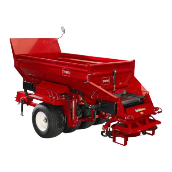
- Page 1 Form No. 3418-742 Rev B MH-400SH2 or MH-400EH2 Material Handler Model No. 44931—Serial No. 401252001 and Up Model No. 44954—Serial No. 401252001 and Up *3418-742* B Register at www.Toro.com. Original Instructions (EN)
- Page 2 Whenever you need service, genuine Toro parts, or additional information, contact an Authorized Service Dealer or Toro Customer Service and have the model and serial numbers of your product ready. Figure 1 identifies the location of the model and serial numbers on the product.
- Page 3 Important: With your mobile device, you can scan the QR code (if equipped) on the serial number decal to access warranty, parts, and other product information. g234791 Figure 1 1. Model and serial number location Model No. Serial No. This manual identifies potential hazards and has safety messages identified by the safety-alert symbol (Figure 2), which signals a hazard that may cause...
-
Page 4: Table Of Contents
Contents Changing the Conveyor Belt ......50 Adjusting the Conveyor Drive Chain....52 Maintaining the Electric Brakes......52 Safety ............... 5 Storage ..............54 General Safety ........... 5 Troubleshooting ............55 Safety and Instructional Decals ......5 Checking Fault Codes (EH Models Setup ................ -
Page 5: Safety
Safety • Keep the machine away from bystanders while it is moving. • Keep children out of the operating area. Never General Safety allow children to operate the machine. • Park the machine on a level surface; engage the This product is capable of causing personal injury. parking brake;... - Page 6 decal119-6819 119-6819 1. Spinner speed percentage 2. Belt speed percentage decal93-9852 93-9852 1. Warning—read the Operator’s Manual. 2. Crushing hazard—install the cylinder lock. decal119-6836 119-6836 decal131-6766 1. Read the Operator's Manual. 131-6766 2. Locate weight so that rear of the weight case is 28 in (71 Model 44954 Only cm) from the front face of hitch tube.
- Page 7 decal119-6806 119-6806 1. Warning—read the Operator's Manual. 4. Warning—shut off the engine, remove the key, and read the Operator's Manual before performing maintenance. 5. Warning—do not carry passengers. 2. Warning—all operators should be trained before operating the machine. 3. Thrown object hazard—keep bystanders away. 6.
- Page 8 decal119-6812 119-6812 1. Tipping hazard—do not turn fast; turn slowly; when the hopper is empty, do not go faster than 15 mph (24 kph); when the hopper is loaded, move slowly; when moving over rough terrain, move slowly. decal119-6863 119-6863 1.
-
Page 9: Setup
Setup Loose Parts Use the chart below to verify that all parts have been shipped. Procedure Description Qty. Bolt (1 x 6-1/2 inches) Install the hitch. Locknut (1 inch) – No parts required Install the weight case. – No parts required Adjust the mirror. -
Page 10: Installing The Hitch
Media and Additional Parts Description Qty. Operator's Manual Read the manual before operating the machine. The Declaration of Conformity serves as EU proof of Declaration of Conformity certification. Attachment clamps Use to mount attachments. Note: Determine the left and right sides of the Slide the hitch tube tongue into place at the front machine from the normal operating position. -
Page 11: Adjusting The Mirror
Installing the Weight Case No Parts Required Procedure Remove the weights from the weight case. Remove the bolts (1/2 x 5-1/2 inch) from the mounting bracket holding the weight case. Discard the mounting brackets (Figure g014069 Figure 6 1. Fill weight case Adjusting the Mirror No Parts Required g014067... -
Page 12: Wiring And Installing To The Tow Vehicle
Connect the Outcross wire harness connector to the brake controller connector. Refer to the Outcross traction unit Operator’s Manual for additional mounting and operating instructions. g015149 Figure 7 g235379 1. Mirror Figure 8 1. Brake controller Tractor Note: Lay out the harness on the tractor to determine Wiring and Installing to the the mounting locations of the harness components. - Page 13 Plug the shorter wire from the harness into may need to be attached to match the the foot controller wire connector. auxiliary power source connection. • Connect the longer wire from the harness to To have the brake controller always the brake controller wire connector.
-
Page 14: Installing The Eh Wireless Control Mounting Bracket On The Tow Vehicle
Installing the EH Wireless Control Mounting Bracket on the Tow Vehicle Model 44954 Only Parts needed for this procedure: g014103 Figure 11 Mounting bracket assembly 1. EH handheld remote backing plate Backing plate Flange head bolt (5/16 x 1-1/2 inches) Note: Also, the wireless remote magnet will stick to Flange head locknut (5/16 inch) -
Page 15: Assembling The Handheld Remote
g014074 Figure 12 1. On/off pendant switch Important: Always remove the on/off pendant switch cord or disconnect the power supply wire when the machine and tow vehicle are not in use. g028875 Otherwise, the tow vehicle battery will lose power. Figure 13 1. -
Page 16: Attaching The Hydraulics To The Tow Vehicle
Attaching the Hydraulics to Attaching the 7-pin Coiled the Tow Vehicle Power Cable No Parts Required Parts needed for this procedure: 7-pin coiled power cable Procedure Note: The tow vehicle must be equipped with an Procedure open center auxiliary hydraulic valve. Attach the 7-pin coiled power cable to the MH-400 For best results, use a tow vehicle with a fixed material handler. -
Page 17: Product Overview
Product Overview Controls Hydraulic Control Valves (SH Model 44931) g234789 g014117 Figure 17 Figure 16 1. E-S Button 1. Conveyor belt direction (left control valve) 2. Raise and lower machine (center control valve) 3. Options on and off (right control valve) Diagnostic LED Function (EH 4. -
Page 18: Specifications
Contact your Authorized Service Dealer or authorized Toro distributor or go to www.Toro.com for a list of all approved attachments and accessories. To ensure optimum performance, use only genuine Toro replacement parts and accessories. -
Page 19: Before Operation
Connecting the Machine to Operation the Tow Vehicle Before Operation Connect the machine hitch to the tow vehicle using a 25 mm (1 inch) diameter safety approved hitch pin and safety clip (not supplied). Before Operation Safety Adjust the hitch height by turning the jack stand handle to keep the machine level. - Page 20 • Before operating the machine for the first time, the electric brakes must be synchronized to the tow vehicle’s brakes (so that they operate at the same time). • The machine and the tow vehicle will seldom have the correct amperage flow to the brake magnets to provide comfortable, safe braking.
-
Page 21: During Operation
During Operation to tow a fully loaded machine to a spot near the job and then load smaller machines from the machine to complete the job. During Operation Safety • When fully loaded, the machine can weigh up to 7,000 kg (15,432 lb). Do not go beyond the •... -
Page 22: Slope Safety
• – Do not attempt sharp turns or abrupt Ensure that the machine is connected to the tow maneuvers or other unsafe driving actions that vehicle before unloading. may cause a loss of control. • Do not travel with the machine in the fully raised –... -
Page 23: Turning The Machine Power On/Off
– Reduce the weight of the load when traveling on steep hills and avoid piling the load high. • Identify hazards at the base of the slope. Use extreme caution when operating the machine near drop-offs, ditches, embankments, water, or other hazards. -
Page 24: Operating The Hydraulic Controls And Options On Eh Models
Left Valve Operating the Hydraulic Controls and Options on The left valve controls the machine conveyor belt direction. EH Models • To unload the machine, pull the control lever toward you. This moves material to the rear along the conveyor belt. Remote Control System •... - Page 25 Button Functions Button Name Primary Function Power the remote on and off. Provides functional control on both the Floor and Option including on/off and TART displaying the speed. Provides functional control of the hopper conveyor floor belt including on/off LOOR TART and displaying the floor speed.
- Page 26 Turning On the Handheld Remote • To lower the hopper (Figure 25), pull out on the ring on the valve stem. Press the O button on the remote and wait • To adjust the spinner speed (Figure 25), use for the it to find the base. Ensure that there are no a flat-head screwdriver to increase by turning buttons being pressed on the hand held while it is clockwise or decrease by turning counter...
- Page 27 Key Functionality Elements • When the handheld remote is first powered on, the display should read FLR OFF and OPT OFF in approximately 5 seconds. If the words “waiting for base” are in the display, check to ensure there is electrical power to the base unit and ensure the button on the base unit is pulled out.
- Page 28 Adjusting the Floor Speed Loosen the jam nut at the manual-override bracket (Figure 30). g285596 Figure 29 1. Adjust floor speed 4. Adjust spinner speed 2. Lower the hopper 5. Cover plate 3. Raise the hopper 6. Decal g285594 Figure 30 1.
- Page 29 Adjusting the Position of the Hopper • To lower the hopper (Figure 31), pull the ring on the valve stem. g285593 Figure 32 1. Hex-head screw (valve override) Once your settings are acceptable, use the hydraulic flow control on your tow vehicle to turn the system on and off during operation.
- Page 30 Using the Liquid Crystal Display Tighten the jam nut (Figure 33). (LCD) Reset the Attachment-Speed Solenoid The 2 line, 8 character-per-line LCD (Liquid Crystal Rotate the flat-head screw counterclockwise until the Display) shows status and activity as the remote valve in the solenoid is fully open (Figure 34).
- Page 31 shorten the life span of the batteries; the lower the backlighting, the longer the battery life span. Understanding the Remote Status The remote status LED blinks slowly at 2 Hz (twice per second) when the handheld remote is transmitting but no buttons are being pressed, when the floor and option buttons are active.
-
Page 32: Operating The Floor And Option
Associating the Handheld Remote Battery Life, Operating Frequency, with the Base Base and Remote ID Display Hold down the A and O The factory initially associates the remote to the base PTION buttons simultaneously to display multiple points of allowing them to communicate; however, there may information. - Page 33 Note: change. The next time you use the remote, the setting Changes to the option settings while the will revert to the previously stored value. option is running are immediately effective, but they are temporary unless you store the new setting by Note: A 10 second timer starts when you press pressing O...
-
Page 34: Setting The Preset 1, 2, And 3 Buttons
indicating that the remote is in a set-only mode. In this set-only mode, you can adjust either setting up or down, but the floor and option do not activate, remaining off. This allows you to set the desired speeds or use the stored settings without causing Press the A button to store the values. -
Page 35: Loading Material
CAUTION then , or Use the adjustable section of the rear gate only when unloading material smaller than 1 inch (25 mm) in diameter, The screen will display PRESET SAVED. such as sand or gravel. Note: If you hold the S button and press a TORE button while either the floor or option are off,... -
Page 36: Using The Twin Spinner
Using the Twin Spinner Installing the Twin Spinner The machine comes equipped with a pair of quick attach mounting clamps. Use these clamps to mount the twin spinner to the machine. Remove the safety latch clips from the clamp handles (Figure 40). - Page 37 g015127 Figure 40 1. Rear of the machine 5. Clamp handle 9. Lift 13. Front clamp brackets 2. Option attachment bracket 6. Safety latch clip 10. Pull 3. Lock pin 7. Safety latch 11. Rear clamp assembly 4. Lock ring 8.
- Page 38 Connecting the Hydraulic Hoses • Hold the male connector firmly in place and release the outer sleeve of the female connector. WARNING • Ensure that the connectors are pushed all the way in and are securely locked in place. Ensure that the tow vehicle is turned off •...
- Page 39 Setting the Desired Spread Pattern You can set the spread pattern to the following settings: • A (Blue)—Ultra Light Pattern • B (Yellow)—Light to Heavy Spread Pattern g015024 Figure 44 1. Spinner valve Rotate the spinner valve lever (Figure 44) to the g015028 desired color (yellow for this example).
- Page 40 EH models: variables include ground speed and the type of material. Different materials vary in particle size, Rotate the crank to adjust the gate (Figure which can vary the spread pattern. until the arrow aligns with the center of the desired color (yellow for this example).
-
Page 41: Setting Up The Cross Conveyor/Swivel
decal119-6866 Figure 47 Setting Up the Cross Conveyor/Swivel Installing the Cross Conveyor/Swivel The cross conveyor spreads material to either side of the machine while the swivel kit allows the cross conveyor to swivel freely in a 270 degree arc, or to be locked into 1 of 5 fixed positions, 45 degrees apart. - Page 42 g015127 Figure 48 1. Rear of the machine 8. Option 2. Option attachment bracket 9. Lift 3. Lock pin 10. Pull 4. Lock ring 11. Rear clamp assembly 5. Clamp handle 12. Support the option before removing the clamps 13. Front clamp brackets 6.
-
Page 43: Operating The Cross Conveyor
on the handheld remote on the EH models, and ensure that the cross conveyor/swivel is operating properly. g014112 Figure 49 1. Option control valve 4. Swivel kit 2. Hose connections 5. Cross conveyor 3. Quick attach clamps Operating the Cross On SH models adjust the speed of the cross conveyor with the hydraulic lever on the right. -
Page 44: Operating The Swivel Kit
g014125 Figure 50 1. Extended position when conveying 5. Swivel lock pin 2. Centered position when traveling 6. Remove or flip up the deflector 3. Cross conveyor 7. Material outlet (motor end) 4. Swivel kit Spreading Material from the Cross To keep the cross conveyor in a fixed position, release the spring-loaded locking pin into 1 of the 5 locking Conveyor... -
Page 45: After Operation
After Operation After Operation Safety • Park the machine on a firm, level surface; engage the parking brake; shut off the engine; remove the key; and wait for all movement to stop before leaving the machine. • Avoid soft ground because the jack leg could sink and cause the machine to tip over. -
Page 46: Maintenance
Maintenance Note: Download a free copy of the schematic by visiting www.Toro.com and searching for your machine from the Manuals link on the home page. Maintenance Safety • Before servicing or adjusting the machine, stop the machine, shut off the engine, engage the parking brake, remove the key, and wait for all moving parts to stop. -
Page 47: Safety Checks
g014131 Figure 53 g014134 Figure 56 Safety Checks At the start of each day, complete these safety checks before operating the machine. Report any safety problems to your supervisor. See the Safety Instructions in this manual for details. Note: Photocopy these pages and use them as a regular safety checklist Tires and Wheels •... -
Page 48: Hydraulic System Safety
(Available in 5 gallon pails or 55 gallon drums. See parts catalog or Toro distributor for part numbers.) Check all rubber seals for wear or damage. Replace Alternate fluids: If the Toro fluid is not available, other or repair the seals if any leakage occurs. petroleum-based Universal Tractor Hydraulic Fluids... -
Page 49: Tracking The Conveyor Belt
6 wheel bolts are tight. Torque in a of the belt. It is set to factory specifications. crossover pattern to 135 N-m (100 ft-lb). Contact your authorized Toro distributor if adjustment is required. Changing an Inside Tire... -
Page 50: Changing The Conveyor Belt
Fully load the machine with sand that you expect Loosen the nut closest to the end of the the machine to use. tensioning rod. Remove the black front covers on either side of Move the inside adjusting nut back until the the machine. - Page 51 Installing the Belt Lower the drive roller down through the slots. Remove the rear gate for a better view. To install a new belt, reverse the above instructions, but keep in mind the following important notes and Note the position of the cartridge inside the instructions.
-
Page 52: Adjusting The Conveyor Drive Chain
Adjusting the Conveyor Maintaining the Electric Brakes Drive Chain If the conveyor drive chain is loose, it needs to be Inspecting the Electric Brakes tightened (Figure 61). Once a month, conduct a simple visual inspection of Shut off the engine of the tow vehicle and your brake shoes and linings. - Page 53 Inspecting the Magnets Replace the brake linings when they are • worn to 1/16 inch (1.6 mm) or less remaining The brakes’ electromagnets are designed to provide thickness the proper input force and friction. • contaminated with grease or oil Inspect the magnets regularly, and replace if they •...
-
Page 54: Storage
Storage Before storing the machine for the season: Thoroughly clean the machine. Remove parts if necessary. Remove the handheld remote. Also, remove the batteries from the Remote. Check all fasteners and tighten, if necessary. Grease all fittings and pivot points. Wipe off any excess lubricant. -
Page 55: Troubleshooting
Troubleshooting Checking Fault Codes (EH Models Only) If the Diagnostic LED indicates that there is a system fault (refer to Diagnostic LED Function (EH Model 44954) (page 17)), check the fault codes to determine what is wrong with the machine. Entering Diagnostic Mode and Checking the Codes Push the E-S button down to turn off the power. - Page 56 Something wrong in the wiring; contact your Toro Distributor. BASE is bad; contact your Toro Distributor. Blink once, pause, blink twice, long Version incompatibility of the BASE Wrong software (install the correct...
-
Page 57: Handheld Remote Messages (Eh Models Only)
Handheld Remote Messages (EH Models Only) Displayed Message Description ASSOC PENDING Association yet to be made. ASSOC ACTIVE Association attempt in progress. POWER UP BASE Power up the Base Unit. ASSOC PASS Association attempt was successful. ASSOC EXIT Exiting Association mode ASSOC FAIL Association attempt failed. - Page 58 The Toro Company (“Toro”) respects your privacy. When you purchase our products, we may collect certain personal information about you, either directly from you or through your local Toro company or dealer. Toro uses this information to fulfil contractual obligations - such as to register your warranty, process your warranty claim or to contact you in the event of a product recall - and for legitimate business purposes - such as to gauge customer satisfaction, improve our products or provide you with product information which may be of interest.
- Page 59 While the exposure from Toro products may be negligible or well within the “no significant risk” range, out of an abundance of caution, Toro has elected to provide the Prop 65 warnings. Moreover, if Toro does not provide these warnings, it could be sued by the State of California or by private parties seeking to enforce Prop 65 and subject to substantial penalties.
- Page 60 Countries Other than the United States or Canada Customers who have purchased Toro products exported from the United States or Canada should contact their Toro Distributor (Dealer) to obtain guarantee policies for your country, province, or state. If for any reason you are dissatisfied with your Distributor's service or have difficulty obtaining guarantee information, contact your Authorized Toro Service Center.
Need help?
Do you have a question about the MH-400SH2 and is the answer not in the manual?
Questions and answers