Advertisement
Service Facts
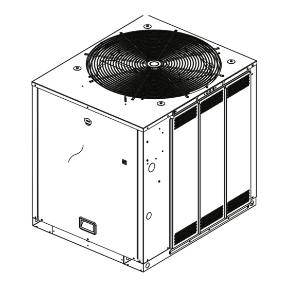
Split System Cooling
Condensers
Single Compressor, R-410A
TTA120D300AA
TTA120D30RAA
TTA120D30SAA
TTA120D30TAA
TTA120D30UAA
TTA120D30WAA
TTA120D400AA
TTA120D40RAA
TTA120D40SAA
TTA120D40TAA
TTA120D40UAA
TTA120D40WAA
August 2009
TTA120DK00AA
TTA120DK0RAA
TTA120DK0SAA
TTA120DK0TAA
TTA120DK0UAA
TTA120DK0WAA
TTA120DW00AA
TTA120DW0RAA
TTA120DW0SAA
TTA120DW0TAA
TTA120DW0UAA
TTA120DW0WAA
TTA120D3H0AA
TTA120D3HRAA
TTA120D3HSAA
TTA120D3HTAA
TTA120D3HUAA
TTA120D3HWAA
TTA120D4H0AA
TTA120D4HRAA
TTA120D4HSAA
TTA120D4HTAA
TTA120D4HUAA
TTA120D4HWAA
SS-SVF15A-EN
TTA120DKH0AA
TTA120DKHRAA
TTA120DKHSAA
TTA120DKHTAA
TTA120DKHUAA
TTA120DKHWAA
TTA120DWH0AA
TTA120DWHRAA
TTA120DWHSAA
TTA120DWHTAA
TTA120DWHUAA
TTA120DWHWAA
Advertisement
Table of Contents

Subscribe to Our Youtube Channel
Related Manuals for Trane TTA120D300AA


Summary of Contents for Trane TTA120D300AA
- Page 1 Service Facts Split System Cooling Condensers Single Compressor, R-410A TTA120D300AA TTA120DK00AA TTA120D3H0AA TTA120DKH0AA TTA120D30RAA TTA120DK0RAA TTA120D3HRAA TTA120DKHRAA TTA120D30SAA TTA120DK0SAA TTA120D3HSAA TTA120DKHSAA TTA120D30TAA TTA120DK0TAA TTA120D3HTAA TTA120DKHTAA TTA120D30UAA TTA120DK0UAA TTA120D3HUAA TTA120DKHUAA TTA120D30WAA TTA120DK0WAA TTA120D3HWAA TTA120DKHWAA TTA120D400AA TTA120DW00AA TTA120D4H0AA TTA120DWH0AA TTA120D40RAA TTA120DW0RAA TTA120D4HRAA...
-
Page 2: Warnings, Cautions And Notices
Use ONLY R-410A rated service equipment or components with this unit. For specific handling concerns with R-410A, please contact your local Trane representative. Failure to use R-410A rated service equipment or components and/or failure to follow proper procedures or the use of non-approved refrigerants, refrigerant substitutes, or refrigerant additives could result in death or serious injury or equipment damage. - Page 3 Warnings, Cautions and Notices WARNING Personal Protective Equipment (PPE) Required! Installing/servicing this unit could result in exposure to electrical, mechanical and chemical hazards. • Before installing/servicing this unit, technicians MUST put on all Personal Protective Equipment (PPE) recommended for the work being undertaken. ALWAYS refer to appropriate MSDS and OSHA guidelines for proper PPE.
- Page 4 USED WITH DESCRIPTION Coil Guard BAYGARD059A TTA120D Hail Guard HOT GAS BY-PASS BAYHGBP010A TTA120D Universal Hot Gas Bypass Kit Trane Communication Interface BAYICSI003A TTA120D Comm 3/4 Communications Interface Isolators BAYISLT005A TTA120D Rubber Isolator Kit BAYISLT023A TTA120D Steel Spring Isolator Kit...
-
Page 5: Refrigerant Circuit
Refrigerant Circuit Figure 1. COOLING ONLY CIRCUIT DIAGRAM COOLING ONLY CIRCUIT DIAGRAM DISCHARGE DISCHARGE TEMPERATURE TEMPERATURE LIMIT (DTL) LIMIT (DTL) HIGH PRESSURE HIGH PRESSURE GAUGE GAUGE SWITCH (HPCO) SWITCH (HPCO) CONNECTION CONNECTION NOTE A NOTE A NOTE A NOTE A FIELD SUPPLIED FIELD SUPPLIED INTER-CONNECTING... -
Page 6: Product Specifications
Product Specifications Table 2. General Data — TTA120D 10 Tons Single Compressor TTA120D3, D4, DW, DK Cooling Performance Gross Cooling Capacity Matched Air Handler 124,000 Condensing Unit Only 112,000 ARI Net Cooling Capacity 120,000 Efficiency Matched Air Handler (EER) 11.2 Condensing Unit Only (EER) 12.2 System Integrated Part Load Value (IPLV) -
Page 7: Sequence Of Operation
Sequence of Operation NOTICE Equipment Damage! Ensure the disconnect for the indoor air handler is closed before operating the system. Operating the outdoor unit without the indoor fan energized can cause unit trip-out on high pressure control and/or liquid flood back to the compressor. Electromechanical Controls General Operation of the system cooling (and optional heating) cycles is controlled by the position of the... - Page 8 Sequence of Operation ReliaTel™ Control Cooling Mode For Zone Sensor Control When the system switch is set to the COOL position and the zone temperature rises above the cooling setpoint, the RTRM energizes the compressor contactor, provided the high and low pressure and the discharge temperature limit controls are closed.
- Page 9 Cooling Pressure Curves Figure 2. TWE120D TTA120D with TWE120D (English) TTA120D with TWE120D (Metric) S uction P res s ure at 4 0 0 CFM/ Ton S uction P res s ure at 4 0 0 CFM/ Ton 1150 1100 1050 1000 68/57 DB/WB...
-
Page 10: Charging Chart
Charging Chart Charging Chart Figure 3. TTA120D TTA120D Charging Curve Remove charge charge Liquid Temperature Leaving OD Coil, °F SS-SVF15A-EN... -
Page 11: Troubleshooting
Troubleshooting SYSTEM FAULTS REFRIGERANT CIRCUIT Head Pressure Too High Head Pressure Too Low Suction Pressure Too High Suction Pressure Too Low Liquid Refrig. Floodback (TXV System) I.D. Coil Frosting Compressor Runs Inadequate or No Cooling ELECTRICAL Compressor & O.D. Fan Do Not Start Compr.
Need help?
Do you have a question about the TTA120D300AA and is the answer not in the manual?
Questions and answers