Table of Contents
Advertisement
Advertisement
Table of Contents

Related Manuals for Versa Networks 700 Series


Summary of Contents for Versa Networks 700 Series
- Page 1 Cloud Services Gateway 700 Series 20.1...
-
Page 2: Table Of Contents
Table of Contents At a Glance......................5 CSG700 Appliance Models ....................... 5 Chassis Views..........................5 Components and Specifications ................7 Front and Rear Panel Components..................9 2.1.1 Front Panel ................................9 2.1.1.1 LEDs ..................................9 2.1.1.2 SIM Card Slots .................................9 2.1.2 Rear Panel ................................9 2.1.2.1 LEDs ..................................10 2.1.2.2 Power Button ................................10 2.1.2.3 Reset Button................................11... - Page 3 Connect a CSG700 Series Appliance ..................20 3.5.1 Step 1: Connect Earth Ground to a CSG700 Series Appliance ................21 3.5.2 Step 2: Connect AC Power to a CSG700 Series Appliance...................21 3.5.3 Step 3: Connect a CSG700 Series Appliance to a Management Console ............21 Return Hardware....................22 Locate the Model and Serial Number ...................
- Page 4 These articles provide an overview of the Cloud Service Gateway (CSG) 700 series appliances, including chassis specifications and components; general safety standards; and instructions for installing, connecting, and replacing an appliance. At a Glance (see page 5) Components and Specifications...
-
Page 5: At A Glance
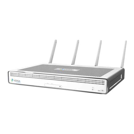
1 At a Glance The Versa Cloud Services Gateway (CSG) 700 series appliances deliver highly secure site-to-site data connectivity to Unified board design that supports different CPUs and memory sizes Up to 10 Ethernet ports including: Two 1-GB EoC or SFP ports, available through separate interfaces... - Page 6 reset buttons and various connectors and ports. This is the side that is visible when you mount the appliance in a 19-inch rack. Figure 1: Front Panel of the CSG730 Appliance Figure 2: Rear Panel of the CSG730 Appliance At a Glance...
-
Page 7: Components And Specifications
2 Components and Specifications A CSG700 series appliance chassis is made of aluminum for optimal heat dissipation. Table 1 lists the specifications for a CSG700 series chassis. Table 1: CSG700 Series Chassis Specifications Item Specification Services and Slot Density RJ-45 ports 10/100/1000 Mbps 4 + 2 SFP Ethernet ports External USB ports (USB 2.0) - Page 8 Item Specification Chassis width 8.75" (22 cm) Chassis depth 13.25" (33.6 cm) Rack height 1 RU Chassis weight 5.84 lb (2.65 kg) Package Specifications Package height 7" (17.78 cm) Package width 16.7" (42.4 cm) Package depth 12" (30.48 cm) Operating Conditions Temperature 0 to 35°C (32 to 95°F) at sea level Humidity...
-
Page 9: Front And Rear Panel Components
2.1 Front and Rear Panel Components This article describes the front and rear panel components of a CSG700 series appliance. For the exact location of these components on the appliance, see At a Glance (see page 5) 2.1.1 Front Panel The front panel of a CSG700 series appliance has two status LEDs and two SIM card slots. -
Page 10: Leds
2.1.2.1 LEDs The rear panel of a CSG700 series appliance has six LEDs located in two rows. Table 2 lists the LEDs, their color and states, and the status they indicate. Table 2: Rear Panel LEDs in a CSG700 Series Appliance Color Status Power... -
Page 11: Reset Button
2.1.2.3 Reset Button The Reset button on the rear panel of a CSG700 series appliance resets the appliance. The reset functionality depends on the number of time you press it, as described in Table 3. The Reset button is recessed so that it is not accidentally pressed while the appliance is operational. To press the Reset button, use a sharp narrow tool. -
Page 12: Interface Numbering
Figure 2 shows the four RJ-45 connectors/SFP slots for the 1-GB EoC/SFP combination port. Figure 2: RJ-45 Connectors or SFP Slots for 1-GB EoC/SFP Combination Port 2.3 Interface Numbering Figure 1 shows the mapping of the Ethernet ports to Virtual Network Interface (VNI) numbering. Figure 3: Port-to-VNI Mapping 2.4 Power Supply and Airflow This article describes the AC power supply, AC power cord specifications, and airflow requirements for CSG700... -
Page 13: Airflow Requirements
Table 1: CSG700 Series Appliance AC Power Supply Specifications Item Specification AC input voltage AC input line frequency Typical power consumption with 35 Watts PoE disabled Typical power consumption with 60 Watts PoE enabled 2.4.2 Airflow Requirements The CSG700 series appliance is made of aluminum for optimal heat dissipation. The appliance has no fans, to minimize noise and to maximize the life of the appliance. -
Page 14: Planning And Installation
3 Planning and Installation This article provides general safety standards and warnings regarding to installing or connecting a CSG 700 series appliances. 3.1 General Safety Guidelines Caution: Before installing or removing a CSG700 series appliance, ensure that the appliance chassis is electrically connected to ground. -
Page 15: Prepare The Site For Installation
3.3 Prepare the Site for Installation To prepare your site for installing a CSG700 series appliance, follow the guidelines and requirements listed in this article. 3.3.1 Site Preparation Guidelines Install the appliance in an enclosed and secure environment, and allow only authorized personnel to access the device. -
Page 16: Install A Csg700 Series Appliance
When planning your site for installing a CSG700 series appliance in a 19-inch rack, allow a minimum of 0.5 RU space above the appliance to allow hot air to flow out of the appliance. However, itt is recommended that you allow 1 RU space above the appliance for cooling. -
Page 17: Packing List For A Csg700 Series Appliance
Note: It is recommended that you save the shipping carton and packing material when unpacking the appliance, in case you need to later move the appliance or return it. See Return Hardware 3.4.2 Packing List for a CSG700 Series Appliance The cardboard carton in which a CSG700 series appliance is shipped contains a packing list. -
Page 18: Mount A Csg700 Series Appliance In A Rack
Component Quantity Power cable 65 Watt PoE power adapter (included with PoE NIC module only) Cat 6 cable Cat 5e cable LTE antenna (included with LTE module only) 2 for single LTE module 4 for dual LTE module WiFi antenna (included with WiFi module only) GPS antenna Rack-mounting ears Screws for mounting ears... - Page 19 4. Attach the two mounting ears to each side of the appliance chassis using the eight mounting ear screws that 5. Grasp both sides of the appliance chassis, making sure that the front of the chassis is facing you. 6. Stand in front of the rack and lift the chassis. Then, gently insert the chassis into the rack and slide it as far Planning and Installation...
-
Page 20: Connect A Csg700 Series Appliance
7. Have the second person secure the mounting ears to the front of the rack using the rack-mount screws that Figure 5: Secure the Mounting Ears to the Rack 3.5 Connect a CSG700 Series Appliance This article describes how to connect a CSG700 series appliance to an AC power source and to a management console. -
Page 21: Step 1: Connect Earth Ground To A Csg700 Series Appliance
3.5.1 Step 1: Connect Earth Ground to a CSG700 Series Appliance To ensure proper operation of a CSG700 series appliance and to meet safety and electromagnetic interference (EMI) requirements, you must connect the appliance to earth ground before you connect power to the appliance. If you use a three-prong power cable to connect power to a CSG700 series appliance, the power cable provide the ground connection. -
Page 22: Return Hardware
4.1 Locate the Model and Serial Number To return a CSG700 series appliance to Versa Networks, you need the model and serial number of the appliance. These numbers are printed on the shipping box and on the unit label located on the bottom of the appliance.
Need help?
Do you have a question about the 700 Series and is the answer not in the manual?
Questions and answers