Table of Contents
Advertisement
Quick Links
Advertisement
Table of Contents

Related Manuals for Ubiquiti PowerBeam airMAX AC Gen2 PBE-5AC-Gen2


Summary of Contents for Ubiquiti PowerBeam airMAX AC Gen2 PBE-5AC-Gen2
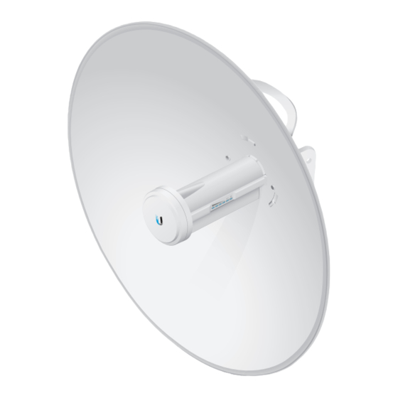
- Page 1 5 GHz High-Performance airMAX ac Bridge ® Model: PBE-5AC-Gen2...
- Page 2 (24V, 0.5A) with Guide Mounting Bracket TERMS OF USE: Ubiquiti radio devices must be professionally installed. Shielded Ethernet cable and earth grounding must be used as conditions of product warranty. TOUGHCable ™ designed for outdoor installations. It is the professional installer’s responsibility to follow local country regulations, including operation within legal frequency channels, output power, and Dynamic Frequency Selection (DFS) requirements.
-
Page 3: Installation Requirements
AC ground of the PoE. We recommend that you protect your networks from harmful outdoor environments and destructive ESD events with industrial‑grade, shielded Ethernet cable from Ubiquiti Networks. For more details, visit www.ubnt.com/toughcable • Surge protection should be used for all outdoor installations. -
Page 4: Hardware Overview
Hardware Overview Bottom View Antenna Feed Technology Ethernet Port Reset Button Release Button Dish Reflector Adjustment Bracket Carrying Handle/ Lifting Loop Alignment Pins Rear Housing Release Button Slot Cable Door... - Page 5 Reset Button To reset to factory defaults, press and hold the Reset button for more than 10 seconds while the PowerBeam is powered on. Alternatively, the PowerBeam may be reset remotely via a Reset button located on the bottom of the Gigabit PoE Adapter.
-
Page 6: Application Examples
Application Examples The PowerBeam mounted outdoors with the Dish Reflector installed provides directional outdoor coverage (gain is reflector‑dependent). The PowerBeam mounted outdoors without the Dish Reflector installed provides outdoor‑to‑indoor coverage using the 3 dBi Antenna Feed only. -
Page 7: Installation
Installation 1. Align and insert the tabs of the Adjustment Bracket into the slots of the Dish Reflector. Rotate the Adjustment Bracket counterclockwise until the alignment holes in the dish and bracket align with each other. 2. Remove the Antenna Feed from the Rear Housing: a. - Page 8 3. Line up the Alignment Pins of the Rear Housing with the alignment holes of the Adjustment Bracket. Push the Rear Housing into the Adjustment Bracket. Note: In high‑wind environments, you can add support with additional hardware (not included): 1. Using the four holes in the Adjustment Bracket as a template, drill four holes into the Dish Reflector with a 4.4 mm or 11/64"...
- Page 9 4. View the Dish Reflector from the front. Ensure that the three hooks (indicated below) of the Rear Housing are fully engaged with the inner wall of the Dish Reflector and locked into place. IMPORTANT: Before proceeding, lightly pull the Rear Housing to confirm that it is locked into place.
- Page 10 b. Lightly pull the Antenna Feed to ensure that it is locked into place and the Release Button is fully engaged. Release Button Bottom View 6. Connect an Ethernet cable to the Ethernet Port of the Antenna Feed. Then re‑attach the Cable Door to the Rear Housing.
- Page 11 7. Attach the Pole Clamp to the Mounting Bracket. a. Hold the Mounting Bracket with its clamps facing you and the Elevation Indicators towards the top. b. Insert the two Long Carriage Bolts through the holes of the Mounting Bracket. c.
- Page 12 8. Mount the Mounting Bracket on the pole and secure it. a. Place the Mounting Bracket against the pole. b. Slide the slot of the Pole Clamp over the adjacent Carriage Bolt. c. Tighten the Flange Nuts of the bolts to 25 N ∙ m to secure the Mounting Bracket to the pole.
- Page 13 9. Locate the two slots on the Adjustment Bracket and the two pivot pins on the Mounting Bracket. Place the Reflector Dish with the attached Mounting Bracket onto the pivot pins, ensuring that they fit securely inside of the slots. Adjustment Bracket Slot Pivot Pin...
- Page 14 10. Install the four Hex Bolts with Washers into the Mounting Bracket. Do not tighten the four Hex Bolts completely.
- Page 15 11. Adjust the elevation angle. a. Pivot the antenna until the Elevation Indicator shows the desired elevation angle. b. Tighten the four Hex Bolts completely. Elevation Indicator...
- Page 16 Connect the power using one of the following options: • Using the included Gigabit PoE Adapter: Go to Connecting to the PoE Adapter. • Using a separate PoE switch: Connect the Ethernet cable from the PowerBeam’s Ethernet port to a PoE‑enabled Ethernet port on the switch.
- Page 17 Accessing airOS via Wi‑Fi Verify connectivity in the airOS Configuration Interface. There are two methods, the UNMS app and Web Portal. Both are ™ available for 15 minutes immediately after you power on the PowerBeam. If necessary, you can power cycle the PowerBeam to re‑enable its Wi‑Fi.
- Page 18 5. Tap Connect on the Login screen. 6. Select your Country and tap Done. 7. Customize your settings as needed.
-
Page 19: Web Portal
Web Portal 1. Connect your device’s Wi‑Fi to the PowerBeam SSID named: PBE-5AC-Gen2:<MAC Address> Note: Ensure that your Wi‑Fi connection has DHCP enabled. 2. Launch a web browser and go to: http://setup.ubnt.com http://setup.ubnt.com 3. Enter ubnt in the Username and Password fields. Select your Country and Language. -
Page 20: Installer Compliance Responsibility
Since Ubiquiti Networks equipment can be paired with a variety of antennas and cables, the Antenna and Output Power fields are provided to the professional installer to assist in... -
Page 21: Specifications
Specifications PBE‑5AC‑Gen2 Dimensions 420 x 420 x 230 mm (16.54 x 16.54 x 9.06") Weight 2.22 kg (4.89 lb) Gain 25 dBi Networking Interface (1) 10/100/1000 Ethernet Port Processor MIPS 74Kc Enclosure Characteristics Antenna Feed Outdoor UV Stabilized Plastic Dish Reflector Powder‑Coated SPCC Max. -
Page 22: Safety Notices
Safety Notices Read, follow, and keep these instructions. Heed all warnings. Only use attachments/accessories specified by the manufacturer. WARNING: Do not use this product in a location that can be submerged by water. WARNING: Avoid using this product during an electrical storm. - Page 23 CE Marking CE marking on this product represents the product is in compliance with all directives that are applicable to it. Country List AT BE BG CY CZ DE DK EE EL ES FR HR LU MT NL PL PT RO BFWA (Broadband Fixed Wireless Access) members noted in blue Note: This device meets Max.
Need help?
Do you have a question about the PowerBeam airMAX AC Gen2 PBE-5AC-Gen2 and is the answer not in the manual?
Questions and answers