Table of Contents
Advertisement
Quick Links
Download this manual
See also:
Startup Manual
Advertisement
Table of Contents
Troubleshooting

Related Manuals for Keysight M9380A


Summary of Contents for Keysight M9380A
- Page 1 Keysight M9380A PXIe Vector Signal Generator 1 MHz to 3 GHz or 6 GHz Notice: This document contains references to Agilent. Please note that Agilent’s Test and Measurement busi- ness has become Keysight Technologies. For more information, go to www.keysight.com.
- Page 2 Keysight ranties of merchantability and fitness for Safety Notices a particular purpose. Keysight shall not be Technologies, Inc. as governed by United The following safety precautions should be liable for errors or for incidental or con- States and international copyright laws.
- Page 3 When connecting sources to switching shield connections for measuring circuits, NOT cards, install protective devices to limit fault Keysight products are designed for use as safety earth ground connections. current and voltage to the card. with electrical signals that are rated Meas-...
- Page 4 의 지 역 에 서 사 용 하 는 것 을 목 적 으 로 합 니 applicability of a replacement component, call 다 CLEANING PRECAUTIONS: an Keysight office for information. To prevent electrical shock, disconnect the No operator serviceable parts inside. Refer Keysight Technologies instrument from servicing to qualified personnel.
-
Page 5: Table Of Contents
Step 1: Unpack and Inspect the Modules Inspect for Damage Return an Instrument for Service Step 2: Verify M9380A Shipment Contents Items included in your Keysight M9380A PXIe CW Source Shipment M9380A Model – Option List Step 3: Install the Software Power up the Controller... -
Page 7: Documentation Map
Documentation Map Keysight M9380A PXIe CW Source... - Page 8 Keysight M9380A PXIe CW Source...
-
Page 9: M9380A Introduction
The scope of this Startup Guide is to detail the processes of receiving and installing the software, modules and cables that comprise the Keysight M9380A PXIe CW Source. Troubleshooting is included to assist you in determining and specifying any failures. If you have any questions after reviewing this information, please contact your local Keysight Technologies Inc. - Page 10 M9380A Introduction Step 5: Verify Operation with the Soft Front Panel (SFP) Step 6: INSTALLATION COMPLETE. Proceed to program your product through the API. Keysight M9380A PXIe CW Source...
-
Page 11: Step 1: Unpack And Inspect The Modules
Should it become necessary to return an instrument for repair or service, follow the steps below: It is recommended that you return all modules and cables for repair and calibration. If your Keysight M9300A PXIe Frequency Reference is operating properly, you need not send it in with the other modules because... -
Page 12: Step 2: Verify M9380A Shipment Contents
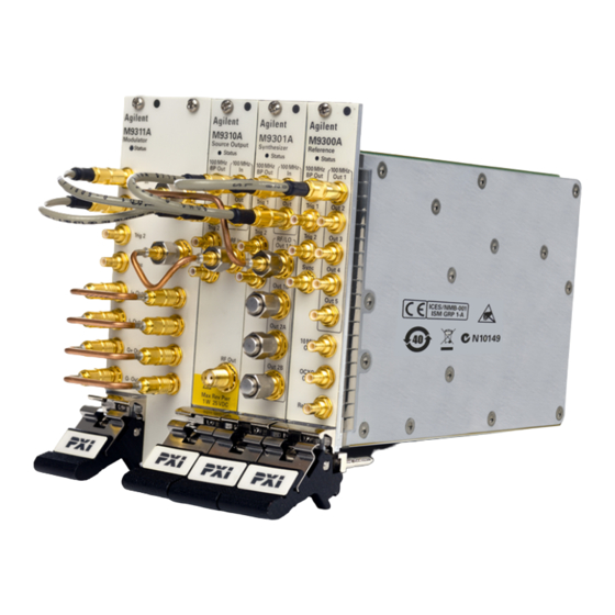
In your correspondence, refer to the modules by serial number and the instrument by model number. Step 2: Verify M9380A Shipment Contents The Keysight M9380A PXIe CW Source is a collection of modules, housed in a PXIe chassis. The minimum CW Source consists of the software, chassis, an Keysight M9301A PXIe Synthesizer, an Keysight M9310A PXIe Source Output and an Keysight M9300A PXIe Frequency Reference. -
Page 13: M9380A Model - Option List
Adaptor, coaxial, straight, SMA (f) to SMA (m) * The Keysight M9300A PXIe Frequency Reference is required to configure an Keysight M9380A PXIe CW Source. It is an option to the M9380A because it may be ordered in, and shared by, the M9381A instrument. - Page 14 Step 2: Verify M9380A Shipment Contents Keysight M9380A PXIe CW Source...
-
Page 15: Step 3: Install The Software
Run one of the operating systems listed in System Requirements (above). Remote con- (for Keysight M9018A chassis use only) A PC running one of the operating systems listed in System Requirements troller above and a Keysight M9021A Cable Interface x8 with one of the following PC interface options:... -
Page 16: Software Installation Overview
Instrument software, which includes the soft front panel (SFP), device drivers (IVI-C, IVI-COM, and LabVIEW G) and doc- umentation for the M9380A PXIe CW Source. This software is included with your shipment (CD part number M9300- 10002) and is also available at www.keysight.com/find/M9380A. -
Page 17: Step 4: Install The Modules
Select a chassis that provides thermal protection if fans become inoperable or forced air cooling is obstructed Use slot blockers (Keysight model Y1212A, 5 per kit) and EMC filler panels in empty module slots to ensure proper operating temperatures. Keysight chassis... -
Page 18: Module Installation Process Overview
See "M9380A Instrument Connections" on page 20 for positioning the M9380A modules. Install the left-most module first and then proceed installing modules from left to right. 6. Holding the module by the injector/ejector handle, slide it into an available PXI (or hybrid) slot, as shown in the following figure. - Page 19 SMA connectors is 8 Lb-In (0.904 Nm). 12. If you are using a PCIe Cable Interface, such as the Keysight M9021, connect the Cable Interface in the chassis to the PC host per the instructions that came with the Cable Interface.
-
Page 20: M9380A Instrument Connections
This section contains a cabling diagram for the Keysight M9380A PXIe CW Source, a cable and module asso- ciation table, a table of Front Panel Features for each module, and a block diagram for the M9380A, with ref- erence tables for each module. -
Page 21: Sharing The M9300A Frequency Reference
Sharing the M9300A Frequency Reference The M9300A Frequency Reference module can be shared by the up to five configurations of the M9380A CW Source or the M9381A Vector Signal Generator. If you connect to a hardware configuration that includes a currently connected M9300A (either independently or as part of another hardware configuration) the latest instance of the SFP will take control of the M9300A. - Page 22 If an existing instance of the SFP is connected to the reference module in a shared (default) mode, and you try to connect a second instance of the SFP to the same reference with ShareRe- ferenceVisaSession=0 Advanced Option, you will get the resource locked error shown above. Keysight M9380A PXIe CW Source...
- Page 23 Step 4: Install the Modules Cable and Connector Care Use the Keysight Cable Removal Tool to disconnect push-on cables from the module front panel con- nectors. To avoid damage to the cables or connectors, pull the cable straight away from the connector. Do not use the tool as a pry bar.
-
Page 24: M9300A Pxie Frequency Reference Front Panel Features
This output is enabled through the SFP. 100 MHz Each of these SMB male connectors may output a 100 MHz reference Out 1 and clock signal to the 100 MHz In connector of the Keysight M9301A through Out PXIe Synthesizer. Trig 1 This connector is intended for future use. -
Page 25: M9301A Pxie Synthesizer Front Panel Features
M9300A PXIe Frequency Reference. 100 MHz Out This SMB male connector outputs the 100 MHz Reference signal to the Keysight M9310A PXIe Source Output 100 MHz In connector. Trig 1 This SMB male connector accepts the External Input Trig- ger. -
Page 26: M9310A Pxie Source Output Front Panel Features
Sync This connector is intended for future use. RF In This SMA female connector inputs the RF signal from the Keysight M9301A PXIe Synthesizer RF Out connector. RF Out This SMA female connector outputs a CW RF signal of 1 MHz to 3 GHz or 6 GHz. -
Page 27: M9380A Block Diagram
M9380A Block Diagram M9380A Block Diagram M9380A Block Diagram Reference Table for M9300A M9300A PXIe Reference Operation Input Connector Output From: External Reference Ref In Frequency: 1 MHz to 110 MHz Input Level: -5 dBm to +20 dBm 100 MHz Out 1-5 Frequency: 100 MHz Output level:>+12 dBm sine (+13 dBm typical) -
Page 28: M9380A Block Diagram Reference Table For M9301A
From : Chassis back plane board 100 MHz BP Out Frequency: 100 MHz Frequency: 100 MHz Output level: +10 dBm M9380A Block Diagram Reference Table for M9301A M9301A PXIe Synthesizer Operation Input Connector Output RF/LO Out 1A, 1B, 2A, 2B Frequency: 187.5 MHz to 6.0 GHz... - Page 29 Trigger 1 & 2 3.3 V into 50 Ω. Trig 1 Output . max @ 0 VDC into 50 Ω (In/Out) Chassis back plane board 100 MHz BP Out Frequency: 100 MHz Output level: >+10 dBm Keysight M9380A PXIe CW Source...
-
Page 30: Step 5: Verify Operation Of The Keysight M9380A Pxie Cw Source
"Com- munications" on page 3. Conduct a Self Test (Utilities > Self Test... > Run Self Test). The M9380A Self Test runs each module through its own Self Test. If the Self Test passes (see results below), go to Step 6: Installation is Complete (page 31). -
Page 31: Step 6: Installation Is Complete
Start > All Programs > Keysight IVI Drivers > AgM938x Source > Documentation. LabVIEW Driver In addition to the IVI drivers, Keysight provides a LabVIEW driver that includes all the functionality of the IVI- C driver. When you install the product software, the LabVIEW driver is installed to each LabVIEW instr.lib dir- ectory for each version of LabVIEW you have on your computer (for example, C:\Program Files (x86)\National Instruments\<LabVIEW version>\instr.lib\<Agilent product model>). -
Page 32: M9380A Specifications
(AgM938x_LabVIEW_Help.chm) from this Start menu location: Start > All Programs > Keysight > M938x > M938x LabVIEW Help. M9380A Specifications The Data Sheet for the M9380A is included on the Software and Product Information CD (M9300-10002) that came with your module. This document contains specification information. Please check the Keysight web- site at www.keysight.com/find/M9380A... -
Page 33: M9380A Troubleshooting
If not all modules and their slot locations are visible in the SFP "Connect to Instrument" dialog: 1. Close the SFP. 2. Start Keysight Connection Expert, by selecting Start > All Programs > Keysight Connection Expert. If any or all mod- ules and their slot locations are still not visible, select Refresh All. -
Page 34: Status Led States
M9380A Troubleshooting Status LED States Once you open the M9380A SFP, select all relevant modules, and then choose Connect. The modules are ini- tialized. Until a module is initialized, the LEDs are off. Module Green Orange M9300A The Soft Front Panel has Indicates that Not connected by the SFP. -
Page 35: M9300A Pxie Frequency Reference Troubleshooting
Source or Function Generator 1 MHz to 110 MHz,0 to 10 dBm Ref In Connector 1. On the M9380A SFP, select the “Reference” tab and under “External” select "Use External Reference. The External Reference status indicator will show an "Unlocked" condition and the Status LED on the M9300A front panel will turn red until an external reference is applied. -
Page 36: M9301A Pxie Synthesizer Troubleshooting
9. Connect the signal analyzer to the 100 MHz BP Out connector and verify that the power is ≥ +10 dBm. 10. If the power level is low, the module is defective and needs to be repaired.See "Return an Instrument for Service" on page M9301A PXIe Synthesizer Troubleshooting This procedure requires that you: Keysight M9380A PXIe CW Source... - Page 37 Span: 500 MHz c. Reference bandwidth and resolution bandwidth to Auto. d. Center Frequency: 1 GHz 6. Set the M9380A, using the SFP, and the signal analyzer to the first of the frequencies listed below: 1.0 GHz 2.0 GHz 3.0 GHz...
- Page 38 8. Reconnect the 100 MHz input from the M9300A. 9. Verify that the signal returns. 10. If the module fails any of the above tests, it needs repair.See "Return an Instrument for Service" on page Keysight M9380A PXIe CW Source...
-
Page 39: M9310A Pxie Source Output Troubleshooting
M9310A PXIe Source Output Troubleshooting Before proceeding, check the outputs of the M9301A and M9311A (if applicable). 1. Verify that all module interconnect cables are properly connected. See "M9380A Instrument Connections" on page 2. Set the signal analyzer to a. Reference level: 30 dBm b.
Need help?
Do you have a question about the M9380A and is the answer not in the manual?
Questions and answers