Keysight M8920A Getting Started Manual
Pxie radio test set
Hide thumbs
Also See for M8920A:
- User & programmers manual (3096 pages) ,
- User manual (2667 pages) ,
- Programmer's reference manual (2650 pages)
Table of Contents
Advertisement
Quick Links
Advertisement
Table of Contents

Related Manuals for Keysight M8920A


Summary of Contents for Keysight M8920A
- Page 1 Getting Started Guide Keysight M8920A PXIe Radio Test Set...
- Page 2 DFARS and are set forth CONTROLLERS, MODULES, ETC.) specifically in writing elsewhere in the PERFORMANCE, SAFETY, OR Manual Part Number EULA. Keysight shall be under no REGULATORY COMPLIANCE, UNLESS M8920-90001 obligation to update, revise or otherwise SPECIFICALLY STATED.
- Page 3 This chassis. that the line cord is connected to a product must be used in a normal Keysight products are designed for use properly-grounded power receptacle. condition (in which all means for with electrical signals that are rated Inspect the connecting cables, test protection are intact) only.
- Page 4 PRODUCT MARKINGS: “Monitoring and Control instrumentation” product. Do not dispose in domestic household waste. To return unwanted products, contact The CE mark is a registered trademark your local Keysight office, or for more of the European Community. information see http://about.keysight.com/en/companyinfo/e nvironment/takeback.shtml.
-
Page 5: Table Of Contents
Step 2 - Verify Shipment Contents and Model Options Shipment Contents Model Options Model - Option List for the M8920A Radio Test Set Model - Option list for the Keysight X-Series Applications Step 3 - Install the Software System Requirements... - Page 6 Address Setting in Local Control Address Setting in Remote Control Hardware License Installation Launch Modular TRX Application Automatically Step 6 - Verifying Operation of the M8920A Auto Align Verify Audio Generation Analysis Verify RF Output Step 7 - Installation is Complete...
- Page 7 Connections Contact integrity Concentricity Male connector: Visual Inspection Obvious Defects or Damage Making Connections Connection Procedure Cleaning Connectors...
- Page 8 viii...
-
Page 9: Introduction
Keysight M9260A PXIe Audio Analyzer module (Audio Analyzer) N9093 Radio Test mode Steps 1 - 7 cover the basics of setting up and configuring the M8920A Radio Test Set, which includes downloading and installing the N9093 Radio Test mode on to your PXIe embedded controller or external controller attached to the PXIe chassis. -
Page 10: Follow The Startup Sequence
Step 4: Install Modules Step 5: Launch Modular TRX application. Step 6: Verify Operation with the N9093 Radio Test mode Radio Test Measurement application. Step 7: INSTALLATION COMPLETE. Proceed to program your product through the API. M8920A Getting Started Guide... -
Page 11: Related Documentation
Introduction Related Documentation To access documentation related to the Keysight M8920A PXIe Radio Test Set, use one of the following methods: If the product software is installed on your PC, you automatically have access to the N9093 Radio Test mode Help system. The other documents described below are available on the CD included in your shipment and at this location: www.keysight.com/find/M8920A. -
Page 12: Security Information
Introduction Security Information The security guide for the M8920A Radio Test Set is located here: www.http://literature.cdn.keysight.com/litweb/pdf/m8920-90006.pdf. M8920A Getting Started Guide... -
Page 13: Step 1 - Unpack And Inspect The Modules
Step 1 - Unpack and Inspect the Modules Step 1 - Unpack and Inspect the Modules The modules are shipped in materials which prevent damage from static. Modules should only be removed from the packaging in an anti-static area ensuring that correct anti-static precautions are taken. -
Page 14: Inspect For Damage
(see warranty information at beginning of this document). If necessary, refer to Returning an Instrument for Service (page 82) for more information. To avoid damage when handling a module, do not touch exposed connector pins. M8920A Getting Started Guide... -
Page 15: Step 2 - Verify Shipment Contents And Model Options
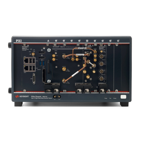
Shipment Contents The Keysight M8920A PXIe Radio Test Set is a multi-module instrument (MMI), housed in a PXIe chassis. This PXIe solution consists of the software, a Keysight M9421A VXT PXIe Vector Transceiver module, a Keysight M9470A PXIe 50 W RF Interface module, and a Keysight M9260A PXIe Audio Analyzer module. -
Page 16: Model Options
Step 2 - Verify Shipment Contents and Model Options Model Options Model - Option List for the M8920A Radio Test Set M8920A Description M8920A-504 Frequency range, 100 kHz to 3.8 GHz PXIe Radio Test Set M8920A-506 Frequency range: 100 kHz to 6 GHz PXIe Radio Test Set... -
Page 17: Step 3 - Install The Software
Step 3 -Install the Software Step 3 - Install the Software The following topics are found in this chapter: System Requirements (page 18) Power Up the Controller (page 22) Software Installation Overview (page 23) Licensing Options (page 30) Licensing Measurement Application Software (page 35) -
Page 18: System Requirements
8 GB available hard disk space, includes: space 1 GB available for Microsoft .NET Framework 4.6 7 GB available for the M8920A Radio Test Set installation software package Video Support for Direct X 11 graphics with 128 MB graphics memory... -
Page 19: Hardware Requirements
Hardware Requirements Topic Requirements Chassis PXIe or PXI-H - 7 slots are required (in total) for the M8920A: M9421A (4 slots), M9470A (2 slots), and M9260A (1 slot). Controllers A PXI or PXI Express embedded controller or remote controller (external PC connected to the chassis by a PCI-to-PXI interface) is required. -
Page 20: Chassis Requirements
The instruments can operate with mains supply voltage fluctuations up to ±10% of the nominal voltage. M9018B and M9019A chassis air flow The Keysight chassis shown above have multiple air intakes. They are located at the sides, front, and bottom of the chassis. M9010A chassis air flow... - Page 21 Step 3 -Install the Software The Keysight M9010A has two fans on the rear panel. They pull air from the rear panel and push air through the chassis. For more information, go to Keysight.com. Refer to the "Keysight PXIe Chassis Family User Guide"...
-
Page 22: Power Up The Controller
1. Install the embedded controller module into the compatible chassis. The Keysight M9037A PXIe embedded controller and Keysight M9010A chassis for benchtop or Keysight M9018B PXIe chassis for rack mount are recommended. Please refer to the embedded controller and chassis documentation for further details. -
Page 23: Software Installation Overview
Instrument software, which includes the N9093 Radio Test mode application, device drivers (IVI-C, IVI-COM, and LabVIEW G) and the Help files for the Keysight M8920A PXIe Radio Test Set. This software is included with your shipment and is also available at: www.keysight.com/find/M8920A. - Page 24 If not, the installation will fail. Exit the installation and clean up the C: drive and try again. 4. After passing the requirements check, the XSA updater splash screen appears. (This may take a few minutes.) M8920A Getting Started Guide...
- Page 25 Step 3 -Install the Software If a modular TRX application has been installed on the controller, the installer will uninstall the earlier version first. 5. The VXT InstallShield Wizard appears. M8920A Getting Started Guide...
- Page 26 6. Select Next. The License Agreement dialog is displayed. Read the license agreement carefully. Select Agree and then select Next to continue. 7. Select Complete as the setup type. M8920A Getting Started Guide...
- Page 27 Step 3 -Install the Software 8. Select Yes, install M9470x and M9260 driver, then select Next. This may take a few minutes. 9. Select Yes, create shortcuts on desktop, then select Next. M8920A Getting Started Guide...
- Page 28 Configure Applications is used to configure certain behaviors of the applications (Modes) at Modular TRX startup . Refer to Configure Application Tool (page 52). 10. The InstallShield Wizard is ready to begin the installation. Select Install to continue. M8920A Getting Started Guide...
- Page 29 The installation takes approximately 20 to 30 minutes to complete. 11. Once the installation is complete, restart the controller before using the application. If the installation fails, a dialog box will display the possible root causes. Follow the instructions to fix the issue and M8920A Getting Started Guide...
-
Page 30: Uninstalling The Software
Uninstalling the Software 1. From the Windows Start menu, go to Control Panel, Programs and Features, Uninstall Programs. 2. Scroll down the list of programs and select Keysight X-Series Modular Vector Signal Transceiver. 3. Select Uninstall to begin the process. -
Page 31: Fixed Licenses
Transportable licenses require a connection to the Keysight server only for managing the transfer of the license to and from the instrument. The connection to the Keysight server may be via the instrument itself or an external PC. The Keysight licensing server also provides for storage of unused licenses that have been transported off instruments but are awaiting assignment to new instruments. -
Page 32: Application Licenses
USB Portable licenses that are "uncounted", will perform comparably to the Fixed and Transportable licenses. Plugging/un-plugging the dongle is equivalent to transporting a license to/from the instrument, however, the software must be restarted whenever the dongle is plugged M8920A Getting Started Guide... -
Page 33: Configuring Network And Usb Licenses
Step 3 -Install the Software Configuring Network and USB Licenses The Keysight Floating License Manager must be used to configure the Network or USB Portable licenses before the licenses can be used. An instrument can be configured for Network or USB Portable licenses or both. To set up USB Portable licenses, in the Keysight Floating License Manager select “Start a floating license... -
Page 34: For Other License Types
Step 3 -Install the Software Windows will detect the new hardware and may display the configuration menu. The M8920A will automatically load the license file. (This may take a few minutes.) Upon completion, the Keysight License Manager will display a "Successful License Installation" message. -
Page 35: Licensing Measurement Application Software
2. Save the .lic file to the root directory on a USB storage device. Connect the USB storage device to the controller. The M8920A automatically loads the license file. This may take a few minutes. Upon completion, Keysight License Manager displays "Successful License Installation". -
Page 36: Install License By Using License Manager
2. Place the license file on a network-connected driver (or somewhere the con- troller can access it). 3. Go to the Windows Start menu, All Programs, Keysight License Manager, Keysight License Manager. Keysight License Manager provides a visual representation of the installed licenses on the controller 4. - Page 37 6. In the Install License dialog, browse to the license file location, select the license file or files and select Open. The install process takes about a minute to complete. 7. To complete the hardware licensing, go to TCP/IP Address Configuration (page 59). M8920A Getting Started Guide...
- Page 38 M8920A Getting Started Guide...
-
Page 39: Step 4 - Install The Modules
Step 4 - Install the Modules The following topics can be found in this chapter: M8920A Modules (page 40) Module Installation Process Overview (page 40) M8920A Instrument Connections (page 43) M8920A Block Diagram (page 45) Module Front Panel Features (page 45) -
Page 40: M8920A Modules
Step 4 -Install the Modules M8920A Modules The M8920A includes three modules that must be installed: Chassis Slots Part Number Module Name Required M9421A Keysight M9421A VXT PXIe Vector Transceiver module M9470A Keysight M9470A PXIe 50 W RF Interface module... - Page 41 5. Before inserting the module into the chassis, back the mounting screws out to ensure that there is no interference between the screws and the mounting rails. 6. See M8920A Instrument Connections (page 43) for positioning the M8920A modules. 7. Holding the module by the injector/ejector handle, slide it into an available PXIe (or hybrid) slot, as shown in the following figure.
- Page 42 Step 4 -Install the Modules 11. If you are using a PCIe cable interface, such as the Keysight M9021A, connect the cable interface in the chassis to the PC host per the instructions that came with the cable interface. 12. Use the...
-
Page 43: M8920A Instrument Connections
Step 4 -Install the Modules M8920A Instrument Connections This section contains a cabling diagram for the Keysight M8920A PXIe Radio Test Set and a cable and module association table. Refer to Cable and Connector Care (page for proper connector care. For front panel feature descriptions, see the following:... -
Page 44: M8920A Cable And Module Table
Step 4 -Install the Modules If using the M9018B or M9019A 18-slot chassis, the recommended Keysight M8920A PXIe Radio Test Set is configured as follows: Recommended Slot Part Number Module Name Slots Required Location M9037A Embedded controller M9421A VXT PXIe vector transceiver... -
Page 45: Multiple Test Sets In A Single Chassis
Step 4 -Install the Modules Multiple Test Sets in a Single Chassis Only two Keysight M8920A PXIe radio test sets can be installed in a single M9018B or M9019A 18-slot PXIe chassis, sharing a single embedded controller. The recommended multiple configuration for the M8920A Radio Test Set is as follows:... -
Page 46: M9421A Vxt Front Panel Connectors
Step 4 -Install the Modules M9421A VXT Front Panel Connectors The instruments can operate with mains supply voltage fluctuations up to ±10% of the nominal voltage. M8920A Getting Started Guide... - Page 47 Sine or square wave –2 V to +5 V max into 50 Ω, +16 dBm max at 0 VDC into 50 Ω This trigger is available for the M8920A. RFIO HD Half duplex port for This port is not available to the M8920A. RF input or RF output RF Input RF input port...
-
Page 48: M9470A Front Panel Connectors
10 MHz reference output port. 100 MHz Out This SMB male connector outputs the 100 MHz reference signal to the M9421A VXT module via a rigid cable. Refer to M8920A Instrument Connections (page 43). M8920A Getting Started Guide... -
Page 49: M9260A Front Panel Connectors
Max output amplitude: 10 Vp Max output current: 50 mA (nom) Output ranges: 0.1 Vp, 0.316 Vp, 1 Vp, 3.16 Vp, 10 Vp in 10 dB steps 5 mVrms (with 0.1 mVrms resolution) to test mic input on M8920A Getting Started Guide... -
Page 50: Front And Rear Panel Symbols
Forty years is the expected useful life of the product. This symbol indicates compliance with the China RoHS regulations for paper- /fiberboard packaging. South Korean Certification (KC) mark; includes the marking’s identifier code which follows this format: MSIP-REM-YYY-ZZZZZZZZZZZZZZ. M8920A Getting Started Guide... -
Page 51: Step 5 - Launch Modular Trx Application
Step 5 - Launch Modular TRX Application Step 5 - Launch Modular TRX Application This chapter provides the information on how to launch a Modular TRX application. Configure Application Tool (page 52) Application Launcher (page 54) Launch Features (page 57) -
Page 52: Configure Application Tool
Modular SA application starts up. Double-click on this icon Configure Applications.exe. If there are multiple products installed, the Configure Applications window will pop up. Select M8920A, Configure. M8920A Getting Started Guide... - Page 53 For information on Launching the TRX application automatically, refer to Launch Modular TRX Application Automatically (page 64). The IQ Analyzer Measurement application is standard with the M8920A and does not require a license. Any additional applications require a license to execute the application. M8920A Getting Started Guide...
-
Page 54: Application Launcher
Start Launcher Click to start Launcher from the Desktop. Alternately, you can start the application from the Windows Start menu, All Programs, Keysight Modular Transceiver, LaunchModular TRX. Hardware License Installation Launcher checks if there are any hardware licenses available for the installed modules. -
Page 55: Fpga Updating
If the FPGA version is different then what is required by the by current Modular TRX, the FPGA on this module will be updated automatically. The following message is displayed and the green Status LED blinks. A popup shows the status of the upgrade. M8920A Getting Started Guide... - Page 56 Step 5 - Launch Modular TRX Application Once the update has completed, turn off the chassis power and turn it back on to enable the update. M8920A Getting Started Guide...
-
Page 57: Launch Features
Combined Model Number - Used as the Unique Identifier (UID), which is a calculated number based on the serial numbers of the three modules. GUI Type Multi-Touch - gives you the choice to use keyboard, mouse or touch screen to navigate the GUI. M8920A Getting Started Guide... - Page 58 The left pane shows a list of installed modules. Select a module to show the hardware licenses in the right pane. App Host ID - Used to redeem software licenses on the controller. Model Host ID - Used to redeem hardware licenses on the controller. M8920A Getting Started Guide...
-
Page 59: Tcp/Ip Address Configuration
2. Select Show Advanced Settings. For the VXT, the HiSLIP Dev value shown is 4. This value will be used to set the remote name in Keysight Connection Expert. Note that you can change the requested HiSLIP port here. If there is a conflict, a new one will automatically be assigned. - Page 60 Step 5 - Launch Modular TRX Application 3. Select the corresponding checkbox and then select Run Selected to start the application. 4. From the Windows Start menu, run Keysight Connection Expert. a. Select the Manual Configuration tab. b. Set the Hostname or IP Address as localhost.
-
Page 61: Address Setting In Remote Control
1. Find the controller's address by selecting then select Show System Settings. 2. From the Windows Start menu, run Keysight Connection Expert. a. Set the Hostname or IP Address as localhost. b. Set the Hostname or IP Address as localhost. -
Page 62: Hardware License Installation
Prior to shipment from the factory, the hardware license is installed in the module. Use the following procedure to upgrade your hardware license to the latest version. 1. Use Keysight License Manager to install the license file on the controller. Refer Install License by Using License Manager (page 36). - Page 63 Install All New HW Licenses button will be disabled (grayed out). 5. Verify the module was installed properly by selecting it in the left column and then verifying the module information in the right column. M8920A Getting Started Guide...
-
Page 64: Launch Modular Trx Application Automatically
1. Right click on the desktop Launch ModularTRX icon and select Properties. 2. Select the Shortcut tab and append the Target string with either /Auto or the PXI VISA address of the module. "C:\Program Files\Keysight\X- Series\MTRX\Infrastructure\LaunchModularSA.exe"\AUTO" M8920A Getting Started Guide... - Page 65 Every time you start Launcher, the application starts automatically, bypassing the Launch Modular TRX settings window. You can drag the LaunchModularTRX.exe into the Startup folder, then the application will automatically launch with the start up of the controller. M8920A Getting Started Guide...
- Page 66 M8920A Getting Started Guide...
-
Page 67: Step 6 - Verifying Operation Of The M8920A
Step 6 - Verifying Operation of the M8920A Step 6 - Verifying Operation of the M8920A Auto Align (page 68) Verify Audio Generation Analysis (page 70) Verify RF Output (page 72) -
Page 68: Auto Align
Step 6 - Verifying Operation of the M8920A Auto Align Before verifying operation, you will need to perform an auto alignment. This should be done, at least once a week any time a module is switched out of the chassis any time a connection change has been made whenever the ambient temperature has change ±5°C... - Page 69 Step 6 - Verifying Operation of the M8920A 4. Select Radio Test Mode, Radio Test Measurement, and Analog Duplex View, then select Okay. 5. Select the (Settings icon) to bring up the System Settings menu. 6. From System Settings, select Alignments, Align Now, Align All Now.
-
Page 70: Verify Audio Generation Analysis
Step 6 - Verifying Operation of the M8920A Verify Audio Generation Analysis 1. On the M9260A PXIe Audio Analyzer module, connect a cable between Ch1 Gen to Ch1 Analyzer. 2. Select the Audio Metrics window to give it the focus. (It will be outlined in blue.) 3. - Page 71 Step 6 - Verifying Operation of the M8920A 5. In the Audio Metrics window, verify that Peak+ is 1.000 V. M8920A Getting Started Guide...
-
Page 72: Verify Rf Output
Step 6 - Verifying Operation of the M8920A Verify RF Output 1. Select the RF Spectrum window to give it the focus. 2. In the Measurement panel, select Frequency. Set Center Frequency to 1 GHz, and Span to 1 MHz. - Page 73 Step 6 - Verifying Operation of the M8920A 6. While monitoring the RF Spectrum, vary the RF power level and watch for a corresponding change in signal amplitude. 7. In the Measurement panel, select Peak Search. Make sure the peak power in both the RF Spectrum and RF Generator window>...
- Page 74 M8920A Getting Started Guide...
-
Page 75: Step 7 - Installation Is Complete
Step 7 - Installationis Complete Step 7 - Installation is Complete Proceed to program your product by means of the application programming interface (API) for the supplied drivers. The following topics can be found in this chapter: IVI Drivers (page 76) LabVIEW Drivers (page 76) -
Page 76: Api Overview
Base - X-Series Signal Analyzers IVI and MATLAB Instrument Drivers LabVIEW Drivers In addition to the IVI drivers, Keysight provides a LabVIEW driver that includes all the functionality of the IVI-C driver. When you install the product software, the LabVIEW driver is installed to each LabVIEW instr.lib directory for each version of LabVIEW you... - Page 77 .chm file) is also installed with the driver and the content is available from LabVIEW's Context Help window. In addition, you can directly access the chm file (AgM9391 LabVIEW_Help) from this Start menu location:Start > All Programs > Keysight > M9391 > M9391 LabVIEW Help.
- Page 78 M8920A Getting Started Guide...
-
Page 79: Troubleshooting
Review the measurement procedures being performed when the problem first appeared. Are all of the settings correct? If the M8920A Radio Test Set solution is not functioning as expected, return it to a known state by selecting , Mode Preset. - Page 80 Troubleshooting http://www.keysight.com/find/M8920A If the M8920A Radio Test Set is not communicating via the LAN connection, check for the presence of blinking yellow LEDs on the rear panel LAN connector. If the ACT LED is not blinking, check the LAN cable and LAN integrity.
-
Page 81: Communications
Troubleshooting Communications If you are unable to communicate with the M8920A verify that the following installations are correct: M8920A software (includes all module drivers) Chassis drivers System interface card, cable and PC PXIe card connections, if you are using an external host PC If all modules and their slot locations are not visible in the SFP "Connect to... -
Page 82: Returning An Instrument For Service
Press System, Show System, and the product numbers, serial numbers, and software revision information will be displayed. Each module has a serial number. The M8920A Radio Test Set has a unique identifier (UID), which is generated automatically from the serial numbers of the individual modules. -
Page 83: Locations For Keysight Technologies
972-3-9288-504/544 39 02 92 60 8484 Netherlands Spain Sweden 31 (0) 20 547 2111 34 (91) 631 3300 0200-88 22 55 Switzerland United Kingdom 0800 80 53 53 44 (0) 118 9276201 Other European Countries: http://www.keysight.com/find/contactus M8920A Getting Started Guide... -
Page 84: Read The Warranty
Service Options Keysight Technologies offers several optional maintenance plans to service your Radio Test Solution after the warranty has expired. Call your Keysight Technologies office for full details. If you want to service the Radio Test Solution yourself after the warranty expires, you can download the service documentation that provides all necessary test and maintenance information from the Keysigt.com. -
Page 85: Packaging The Instrument
6. Seal the shipping container securely with strong nylon adhesive tape. 7. Mark the shipping container “FRAGILE, HANDLE WITH CARE” to assure careful handling. 8. Retain copies of all shipping papers. M8920A Getting Started Guide... - Page 86 M8920A Getting Started Guide...
-
Page 87: Cable And Connector Care
Making Connections (page 91) Cleaning Connectors (page 92) Module Cable and Connector Care Use the Keysight cable removal tool to disconnect push-on cables from the module front panel connectors. To avoid damage to the cables or connectors, pull the cable straight away from the connector. -
Page 88: Contact Integrity
Cable and Connector Care Contact integrity Refer to the following for visual guidelines when evaluating the contact integrity of a connector. Concentricity The following examples show the concentricity of both the male and female 1.0 mm connectors: Female connector: M8920A Getting Started Guide... -
Page 89: Male Connector
Cable and Connector Care Male connector: M8920A Getting Started Guide... -
Page 90: Visual Inspection
Bare metal showing Burrs or blisters Deformed threads Center conductors Bent Broken Misaligned Concentricity Connector nuts should move smoothly and be free of: Burrs Loose metal particles Rough spots Any connector that has obvious defects should be discarded. M8920A Getting Started Guide... -
Page 91: Making Connections
7. Relieve any side pressure on the connection from long or heavy devices or cables. This assures consistent torque. 8. Torque the cable or device to the final value using a torque wrench. M8920A Getting Started Guide... -
Page 92: Cleaning Connectors
3. Add a few drops of high-purity isopropyl alcohol to a small cleaning swab (do not apply alcohol directly to the parts). 4. Gently wipe connecting surfaces with the end of the cleaning swab. 5. Blow dry with compressed air. 6. Inspect and repeat cleaning procedure if necessary. M8920A Getting Started Guide... - Page 93 This information is subject to change without notice. © Keysight Technologies 2018 Edition 1, June 2018 M8920-90001 www.keysight.com...
Need help?
Do you have a question about the M8920A and is the answer not in the manual?
Questions and answers