
Related Manuals for Keysight M9241A


Summary of Contents for Keysight M9241A
- Page 1 Keysight M9241/42/43A PXIe Oscilloscopes and M9240A AutoProbe Power Module Startup Guide...
- Page 2 FAR 2.101, pursuant to FAR terms in the separate agreement shall 12.211 and 27.404.2 and DFARS 227.7102, control. the U.S. government acquires no greater Keysight M9241/42/43A PXIe Oscilloscopes and M9240A AutoProbe Power Module Startup Guide...
-
Page 3: Table Of Contents
Maximum input voltage at Ref I/O connector / 23 Cleaning the Instrument / 24 5 Install the Software System Requirements / 25 Hardware Requirements / 25 Chassis Requirements / 26 Power Up the Controller / 27 Keysight M9241/42/43A PXIe Oscilloscopes and M9240A AutoProbe Power Module Startup Guide... - Page 4 Step 5: (Recommended) Phase-Lock Oscilloscope Sampling Clocks / 54 Step 6: (Optional) Turn On Sync Mode / 55 Step 7: Make Coordinated Acquisitions / 60 9 Applications Programming Interface (API) Overview IVI Drivers / 61 Keysight M9241/42/43A PXIe Oscilloscopes and M9240A AutoProbe Power Module Startup Guide...
- Page 5 Probes and Accessories / 68 Specifications and Characteristics / 68 Measurement Category / 68 Oscilloscope Measurement Category / 68 Measurement Category Definitions / 69 Product Markings / 69 Index Keysight M9241/42/43A PXIe Oscilloscopes and M9240A AutoProbe Power Module Startup Guide...
- Page 6 Keysight M9241/42/43A PXIe Oscilloscopes and M9240A AutoProbe Power Module Startup Guide...
-
Page 7: Introduction
The chapters in this guide cover the basics of setting up and configuring a PXIe oscilloscope system, as well as installing the required software. If you have any questions after reviewing this information, please contact your local Keysight Technologies representative or contact us through our website at www.keysight.com/find/pxi-digitizers. Follow the Startup Sequence Closely follow the startup process flow in this document. -
Page 8: Related Documentation
To access documentation related to the Keysight M9241/42/43A PXIe oscilloscope modules and the Keysight M9240A AutoProbe power module, use one of the following methods: • The related documents are available on the product CD: Keysight M9241/42/43A PXIe Oscilloscopes and M9240A AutoProbe Power Module Startup Guide... - Page 9 The data sheet introduces the product and provides full product specifications. You can find the data sheet at: www.keysight.com/products/M9241A The Keysight M9241/42/43A PXIe Oscilloscopes and M9240A AutoProbe Power Module Security Guide is available at www.keysight.com/find/security. Keysight M9241/42/43A PXIe Oscilloscopes and M9240A AutoProbe Power Module Startup Guide...
- Page 10 Introduction Keysight M9241/42/43A PXIe Oscilloscopes and M9240A AutoProbe Power Module Startup Guide...
-
Page 11: Unpack And Inspect The Module
Keysight M9241/42/43A PXIe Oscilloscopes and M9240A AutoProbe Power Module Startup Guide 2 Unpack and Inspect the Module Inspect for Damage / 12 Return an Instrument for Service / 12 The modules are shipped in materials which prevent damage from static. Modules... -
Page 12: Inspect For Damage
Should it become necessary to return an instrument for repair or service, follow the steps below: It is recommended that you return all modules and cables of the M924xA instrument for repair NOTE and calibration. Keysight M9241/42/43A PXIe Oscilloscopes and M9240A AutoProbe Power Module Startup Guide... - Page 13 Unpack and Inspect the Module Review the warranty information shipped with your product. Contact Keysight to obtain a Return Material Authorization (RMA) and return address. For assistance finding Keysight contact information, go to www.keysight.com/find/assist. Write the following information on a tag and attach it to the malfunctioning equipment: •...
- Page 14 Unpack and Inspect the Module Keysight M9241/42/43A PXIe Oscilloscopes and M9240A AutoProbe Power Module Startup Guide...
-
Page 15: Verify Shipment Contents And Model Options
Keysight M9241/42/43A PXIe Oscilloscopes and M9240A AutoProbe Power Module Startup Guide 3 Verify Shipment Contents and Model Options M9241/42/43A PXIe Oscilloscope Shipment Contents / 15 M9240A AutoProbe Power Module Shipment Contents / 16 M9241/42/43A PXIe Oscilloscope Shipment Contents Items included in your M9241/42/43A PXIe oscilloscope shipment:... -
Page 16: M9240A Autoprobe Power Module Shipment Contents
Software and Product Information CD, contains: Soft Front Panels, drivers, and all printed documentation in PDF format (also available at http://www.keysight.com/support/M9241A) M9240-97xxx Keysight M9241/42/43A PXIe Oscilloscopes and M9240A AutoProbe Power Module Startup Guide in hard copy Keysight M9241/42/43A PXIe Oscilloscopes and M9240A AutoProbe Power Module Startup Guide... -
Page 17: Install The Modules
Keysight M9241/42/43A PXIe Oscilloscopes and M9240A AutoProbe Power Module Startup Guide 4 Install the Modules Module Installation Process Overview / 17 Front Panel Features / 19 Cleaning the Instrument / 24 PXI hardware does not support "hot-swap" (changing modules while power is applied CAUTION to the chassis) capabilities. - Page 18 When using the Keysight M9018A Chassis you will achieve the highest data throughput for the NOTE Keysight M9241/42/43A PXIe oscilloscopes by using Slots 2, 6, 11 or 15. They are "x8" slots and the others are "x4". For further details see the Keysight M9018A Chassis documentation.
-
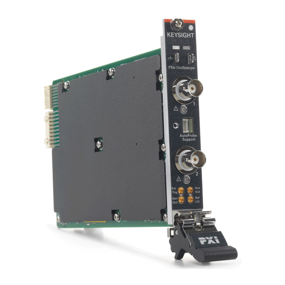
Page 19: Front Panel Features
The left-most slot does not accept a slot blocker. If you are using a PCIe Cable Interface, such as the Keysight M9021, connect the Cable Interface in the chassis to the PC host per the instructions that came with the Cable Interface. -
Page 20: Led Operation
(Left/Right module) • There is a power fault. • The associated module is shut down (that is, no driver is connected). Green Neither of the red conditions is true Keysight M9241/42/43A PXIe Oscilloscopes and M9240A AutoProbe Power Module Startup Guide... -
Page 21: Autoprobe Interface
AutoProbe Support connector. Once the faceplate connections have been established, tighten the faceplate's thumbscrew to secure When the M9240A AutoProbe power module faceplates are connected, the oscilloscope input channels have AutoProbe interface connectors. Keysight M9241/42/43A PXIe Oscilloscopes and M9240A AutoProbe Power Module Startup Guide... -
Page 22: Inputs And Outputs
The 50 input protection Ω only functions when the oscilloscope is powered on. When measuring voltages over 30 V, use a 10:1 probe. CAUTION Keysight M9241/42/43A PXIe Oscilloscopes and M9240A AutoProbe Power Module Startup Guide... -
Page 23: Maximum Voltage At Oscilloscope External Trigger Input
1M ohm input: For steady-state sinusoidal waveforms derate at 20 dB/decade above 100 kHz to a minimum of 5 Vpk For information on using the Ext Trig input, see the Keysight M9241/42/43A PXIe Oscilloscopes Soft Front Panel (SFP) User's Guide. -
Page 24: Cleaning The Instrument
50 Ohm source impedance. For information on using Ref I/O as an input or output, see the Keysight M9241/42/43A PXIe Oscilloscopes Soft Front Panel (SFP) User's Guide. Cleaning the Instrument Remove power from the instrument. -
Page 25: Install The Software
Keysight M9241/42/43A PXIe Oscilloscopes and M9240A AutoProbe Power Module Startup Guide 5 Install the Software System Requirements / 25 Hardware Requirements / 25 Chassis Requirements / 26 Power Up the Controller / 27 Software Installation Overview / 27 Updating Module Firmware as New Modules Are Installed / 28... -
Page 26: Chassis Requirements
Run one of the operating systems listed in System Requirements (above). Remote controller (for Keysight M9018A chassis use only) A PC running one of the operating systems listed in System Requirements above and a Keysight M9021A Cable Interface x8 with one of the following PC interface options: •... -
Page 27: Power Up The Controller
When installing the IO Libraries Suite and instrument software, either use the two CDs CAUTION shipped with the product OR the two download files from keysight.com. Installing a mix of CD and keysight.com download files can result in incompatible software versions. -
Page 28: Updating Module Firmware As New Modules Are Installed
FPGA updates separately: • From the Windows Start menu, choose All Programs > Keysight InfiniiVision Oscilloscope > Update Keysight InfiniiVision Firmware. Keysight M9241/42/43A PXIe Oscilloscopes and M9240A AutoProbe Power Module Startup Guide... -
Page 29: Verify Operation
• Using the Keysight InfiniiVision Launcher. Keysight Connection Expert Method Click the Keysight IO Libraries Suite icon in the task bar and choose Connection Expert from the popup menu. In the Keysight Connection Expert window, select the PXI/AXIe Chassis tab;... - Page 30 Verify Operation The Keysight InfiniiVision M924xA SFP will open: Keysight M9241/42/43A PXIe Oscilloscopes and M9240A AutoProbe Power Module Startup Guide...
-
Page 31: Keysight Infiniivision Launcher Method
Verify Operation The Keysight InfiniiVision M924xA SFP has the same user interface as other standalone Keysight InfiniiVision oscilloscopes. Keysight InfiniiVision Launcher Method From the Windows operating system Start menu, choose Start > All Programs > Keysight InfiniiVision Oscilloscope > Keysight InfiniiVision SFP. - Page 32 Verify Operation The Keysight InfiniiVision M924xA SFP will open: The Keysight InfiniiVision M924xA SFP has the same user interface as other standalone Keysight InfiniiVision oscilloscopes. Keysight M9241/42/43A PXIe Oscilloscopes and M9240A AutoProbe Power Module Startup Guide...
-
Page 33: Run The Oscilloscope's Hardware Self Test
Verify Operation If not all modules and their slot locations are visible in the Keysight InfiniiVision Launcher window: Close the Keysight InfiniiVision Launcher. Start the Keysight Connection Expert, by selecting Start > All Programs > Keysight Connection Expert. If any or all modules and their slot locations are still not visible, in the Instruments tab, click Rescan. -
Page 34: If There Are Communications Problems
• Keysight IO Libraries Suite • M924xA SFP programs • Module and chassis drivers • System Interface Card, cable and PC PXIe card connections, if you are using an external host PC Keysight M9241/42/43A PXIe Oscilloscopes and M9240A AutoProbe Power Module Startup Guide... -
Page 35: Make A Measurement
Compensate Passive Probes / 39 Turn On Measurements and Statistics / 40 Learn the Oscilloscope Display / 41 This chapter assumes you are using the Keysight InfiniiVision M924xA Soft Front Panel (SFP). If you have not already opened the SFP, see "Open the M924xA Oscilloscope Soft Front Panel (SFP)"... -
Page 36: Input A Signal
Connect the probe's ground lead to the ground terminal (next to the Probe Comp terminal). Using the Soft Front Panel (SFP) Interface The Keysight InfiniiVision M924xA SFP has the same user interface as other standalone Keysight InfiniiVision oscilloscopes. While standalone oscilloscopes have keys, softkeys, and knobs—obviously different than the modular oscilloscopes—the display interface was also designed to be used with touch... -
Page 37: Select The User Interface Language
Choose Main Menu > Defaul t Setup. The default setup restores the oscilloscope's default settings. This places the oscilloscope in a known operating condition. The major default settings are: Keysight M9241/42/43A PXIe Oscilloscopes and M9240A AutoProbe Power Module Startup Guide... -
Page 38: Use Autoscale
Use Autoscale to automatically configure the oscilloscope to best display the input signals. Choose Main Menu > Autoscale. You should see a waveform on the oscilloscope's display similar to this: Keysight M9241/42/43A PXIe Oscilloscopes and M9240A AutoProbe Power Module Startup Guide... -
Page 39: Compensate Passive Probes
Click the channel button to which the probe is connected (color-coded 1, 2, etc. at the top of the SFP window). In the Channel Menu, click Probe. In the Channel Probe Menu, click Probe Check; then, follow the instructions on-screen. Keysight M9241/42/43A PXIe Oscilloscopes and M9240A AutoProbe Power Module Startup Guide... -
Page 40: Turn On Measurements And Statistics
To turn on measurements, choose Main Menu > Measure > Measurements. To turn on measurement statistics, choose Main Menu > Measure > Statistics. You should see a display similar to this: Keysight M9241/42/43A PXIe Oscilloscopes and M9240A AutoProbe Power Module Startup Guide... -
Page 41: Learn The Oscilloscope Display
Make a Measurement Learn the Oscilloscope Display The oscilloscope display contains acquired waveforms, setup information, measurement results, and the softkey definitions. Keysight M9241/42/43A PXIe Oscilloscopes and M9240A AutoProbe Power Module Startup Guide... - Page 42 To undock or redock sidebar dialog boxes, drag the dialog box titles out of or back into the sidebar information area. Keysight M9241/42/43A PXIe Oscilloscopes and M9240A AutoProbe Power Module Startup Guide...
- Page 43 At the top of the menu hierarchy, clicking the left-side up-arrow button turns off softkey labels and displays additional status information describing channel offset and other configuration parameters. Keysight M9241/42/43A PXIe Oscilloscopes and M9240A AutoProbe Power Module Startup Guide...
- Page 44 Make a Measurement Keysight M9241/42/43A PXIe Oscilloscopes and M9240A AutoProbe Power Module Startup Guide...
-
Page 45: Coordinating Multiple Pxie Oscilloscope Modules
(because the master module may send triggers when the slave module is not armed). This chapter assumes you are using the Keysight InfiniiVision M924xA Soft Front Panel (SFP). If you have not already opened the SFP, see "Open the M924xA... -
Page 46: Step 1: (Optional) Update The Calibration Factors
Bus segment number where slave module is located. Trigger bus segments are assigned as follows: 18-Slot Chassis Slots 1-6: Trig bus segment number 1 Slots 7-12: Trig bus segment number 2 Keysight M9241/42/43A PXIe Oscilloscopes and M9240A AutoProbe Power Module Startup Guide... - Page 47 C:\Program Files (x86)\Keysight\InfiniiVision> The chassis bus number can be found in the Keysight Connection Expert window: Click the Keysight IO Libraries Suite icon in the task bar and choose Connection Expert from the popup menu. In the Keysight Connection Expert window, PXI/AXIe Chassis > Chassis Content...
- Page 48 InfiniiVision>KtScopeCal.exe PXI8::5::INSTR slot6 trig0 Trigger line PXI TRIG 0 bus segment configured: Isolated Connect Aux Out from master module at slot 5 to channel 1 of master m odule Keysight M9241/42/43A PXIe Oscilloscopes and M9240A AutoProbe Power Module Startup Guide...
-
Page 49: Step 2: Set Up The Slave Modules
Soft Front Panel (SFP) application to connect the selected PXI_TRIG line between trigger bus segments. See "Step 4: (When Necessary) Connect Chassis Bus Segments" on page 51. Keysight M9241/42/43A PXIe Oscilloscopes and M9240A AutoProbe Power Module Startup Guide... -
Page 50: Step 3: Set Up The Master Module
Soft Front Panel (SFP) application to connect the selected PXI_TRIG lines between trigger bus segments. See "Step 4: (When Necessary) Connect Chassis Bus Segments" on page 51. Keysight M9241/42/43A PXIe Oscilloscopes and M9240A AutoProbe Power Module Startup Guide... -
Page 51: Step 4: (When Necessary) Connect Chassis Bus Segments
PXI TRIG 2 as arm lines. You would fllow these steps: Click the Keysight IO Libraries Suite icon in the task bar and choose Connection Expert from the popup menu. In the Keysight Connection Expert window, PXI/AXIe Chassis > Chassis Triggers tab, hover over the lines in the bus segments you would like to reserve, and then click Click to reserve. - Page 52 Coordinating Multiple PXIe Oscilloscope Modules When lines in bus segments are reserved, it will look something like: Keysight M9241/42/43A PXIe Oscilloscopes and M9240A AutoProbe Power Module Startup Guide...
- Page 53 Coordinating Multiple PXIe Oscilloscope Modules Next, click the route directions to be used: Keysight M9241/42/43A PXIe Oscilloscopes and M9240A AutoProbe Power Module Startup Guide...
-
Page 54: Step 5: (Recommended) Phase-Lock Oscilloscope Sampling Clocks
Coordinating Multiple PXIe Oscilloscope Modules Finally, click OK. The Keysight M9018A PXIe Chassis does not remember the trigger bus configuration CAUTION upon cycling power. After a power cycle, you must reconfigure the bus triggers by using the M9018A Soft Front Panel (SFP) or by creating a persistent configuration by using the AgM9018 API. -
Page 55: Step 6: (Optional) Turn On Sync Mode
To align the reference clock signals, you must run the KtScopeCal.exe application using the "-a" or "-p" option: • If setting up Sync mode triggers on a new or modified system, use the command. For example: KtScopeCal -a Keysight M9241/42/43A PXIe Oscilloscopes and M9240A AutoProbe Power Module Startup Guide... - Page 56 Iteration = 4 Mean = 4031 Mean change = 950 Iteration = 5 Mean = 3717 Mean change = 636 Iteration = 6 Mean = 2595 Mean change = -486 Keysight M9241/42/43A PXIe Oscilloscopes and M9240A AutoProbe Power Module Startup Guide...
- Page 57 • When clock phase alignment is lost, use the command to KtScopeCal -r reset/realign the clock phase. For example: Keysight M9241/42/43A PXIe Oscilloscopes and M9240A AutoProbe Power Module Startup Guide...
- Page 58 Connect Aux Out from master module at slot 5 to channel 1 of master m odule and channel 1 of slave module at slot 6 using BNC tee adapter with 50ohm cables of equal length. Keysight M9241/42/43A PXIe Oscilloscopes and M9240A AutoProbe Power Module Startup Guide...
- Page 59 Mean change = 99 Iteration = 40 OutSel = 0 Tdelay = 39 Sync mode calibration passed. Master slot 5, Slave slot 6, Trigger li ne 0. C:\Program Files (x86)\Keysight\InfiniiVision> Keysight M9241/42/43A PXIe Oscilloscopes and M9240A AutoProbe Power Module Startup Guide...
-
Page 60: Step 7: Make Coordinated Acquisitions
"soft stop" makes sure that data across the multiple modules are from the same trigger. If you abort a "soft stop", be aware that the module's data may not be from the same CAUTION trigger as other modules' data. Keysight M9241/42/43A PXIe Oscilloscopes and M9240A AutoProbe Power Module Startup Guide... -
Page 61: Applications Programming Interface (Api) Overview
Panel (SFP) or program the instrument using the applications programming interface (API) for the supplied drivers. IVI Drivers Keysight's IVI drivers simplify the creation and maintenance of instrument control applications in a variety of development environments; they allow programmatic control of instrumentation while providing a greater degree of instrument interchangeability and code reuse. -
Page 62: Labview Driver
Instrument Drivers > IVI-COM-C AgInfiniiVision Oscilloscope. LabVIEW Driver In addition to the IVI drivers, Keysight provides a LabVIEW driver that includes all the functionality of the IVI-C driver. When you install the product software, the LabVIEW driver is installed to each LabVIEW instr.lib directory for each version of LabVIEW you have on your... -
Page 63: Using The Sfp And The Remote Api At The Same Time
Another easy way to send a Device Clear is through the IO Libraries Suite's Interactive IO application. On a networked PC that has the IO Libraries Suite installed, click the Keysight IO Control icon in the taskbar and choose Utilities > Interactive IO from the popup menu. - Page 64 "TCPIP0::lab-pxi-3.cos.is.keysight.com::hislip37-0.0::INSTR"). If you are running the Interactive IO application on the controller PC, you can use the "127.0.0.1" localhost IP address, for example, "TCPIP0::127.0.0.1::hislip37-0.0::INSTR". When connected, click Device Clear. Keysight M9241/42/43A PXIe Oscilloscopes and M9240A AutoProbe Power Module Startup Guide...
- Page 65 Applications Programming Interface (API) Overview To exit the Keysight Interactive IO application, choose Connect > Exit from the menu. Keysight M9241/42/43A PXIe Oscilloscopes and M9240A AutoProbe Power Module Startup Guide...
- Page 66 Applications Programming Interface (API) Overview Keysight M9241/42/43A PXIe Oscilloscopes and M9240A AutoProbe Power Module Startup Guide...
-
Page 67: 10 Reference
Keysight M9241/42/43A PXIe Oscilloscopes and M9240A AutoProbe Power Module Startup Guide 10 Reference Environmental Conditions / 67 Probes and Accessories / 68 Specifications and Characteristics / 68 Measurement Category / 68 Product Markings / 69 Environmental Conditions The Keysight M9241/42/43A PXIe oscilloscopes and M9240A AutoProbe power module products have been safety-evaluated to the M9018A PXIe 18-slot chassis environmental characteristics. -
Page 68: Probes And Accessories
68 • "Measurement Category Definitions" on page 69 Oscilloscope Measurement Category The InfiniiVision oscilloscopes are not intended to be used for measurements in Measurement Category II, III, or IV. Keysight M9241/42/43A PXIe Oscilloscopes and M9240A AutoProbe Power Module Startup Guide... -
Page 69: Measurement Category Definitions
EU law as of August 13, 2005. All electric and electronic equipment are required to be separated from normal waste for disposal (Reference WEEE Directive 2002/96/EC). Keysight M9241/42/43A PXIe Oscilloscopes and M9240A AutoProbe Power Module Startup Guide... - Page 70 This is also a symbol of an Industrial Scientific and Medical Group 1 Class A product (CISPR 11, Clause 4). The CSA mark is a registered trademark of the CSA International. Keysight M9241/42/43A PXIe Oscilloscopes and M9240A AutoProbe Power Module Startup Guide...
- Page 71 NFC automated test, Interactive IO, damage, inspect for, notices, introduction, data sheet, Italian user interface and Quick Help, default configuration, IVI drivers, default setup, Keysight M9241/42/43A PXIe Oscilloscopes and M9240A AutoProbe Power Module Startup Guide...
- Page 72 SCPI interface, SENT triggering and analysis, setup, default, SFP and remote API, concurrent, shipment contents, shipment contents, M9240A, shipment contents, M9241/42/43A, Simplified Chinese user interface and Quick Help, single acquisitions, Keysight M9241/42/43A PXIe Oscilloscopes and M9240A AutoProbe Power Module Startup Guide...
Need help?
Do you have a question about the M9241A and is the answer not in the manual?
Questions and answers