Keysight M8920B Getting Started Manual
Pxie radio test set
Hide thumbs
Also See for M8920B:
- User & programmers manual (3096 pages) ,
- User manual (2667 pages) ,
- Programmer's reference manual (2650 pages)
Table of Contents
Advertisement
Quick Links
Advertisement
Table of Contents

Subscribe to Our Youtube Channel
Related Manuals for Keysight M8920B


Summary of Contents for Keysight M8920B
- Page 1 M8920B PXIe Radio Test Set GETTING STARTED GUIDE...
- Page 2 DOCUMENT OR OF ANY INFORMATION of these rights customarily provided to CONTAINED HEREIN. SHOULD the public to use, modify, reproduce, Copyright Notice KEYSIGHT AND THE USER HAVE A release, perform, display, or disclose SEPARATE WRITTEN AGREEMENT commercial computer software or © Keysight Technologies 2024...
- Page 3 This chassis. properly-grounded power receptacle. product must be used in a normal Keysight products are designed for use Inspect the connecting cables, test condition (in which all means for with electrical signals that are rated leads, and jumpers for possible wear, protection are intact) only.
- Page 4 Annex 1, this product is classified as “Monitoring and Control instrumentation” product. Do not The CE mark is a registered trademark dispose in domestic household waste. of the European Community. To return unwanted products, contact your local Keysight office, or for more information see http://about.keysight.com/en/companyinfo/e nvironment/takeback.shtml.
-
Page 5: Table Of Contents
Step 2 - Verify Shipment Contents and Model Options Shipment Contents Model Options Model - Option List for the M8920B Radio Test Set Model - Option list for the Keysight X-Series Applications Step 3 - Install the Software System Requirements... - Page 6 Hardware License Installation Launch the Modular TRX Application Bind and Launch the Modular TRX Application Manually Launch Modular TRX Application Automatically Step 6 - Verifying Operation of the M8920B Alignment Verify Audio Generation Analysis Verify RF Output Step 7 - Installation is Complete...
- Page 7 Module Cable and Connector Care Connections Contact integrity Concentricity Male connector: Visual Inspection Obvious Defects or Damage Making Connections Connection Procedure Cleaning Connectors...
- Page 8 viii...
-
Page 9: Introduction
Keysight M9260A PXIe Audio Analyzer module (Audio Analyzer) N9093 Radio Test mode Steps 1 - 7 cover the basics of setting up and configuring the M8920B Radio Test Set, which includes downloading and installing the N9093 Radio Test mode on to your PXIe embedded controller or external controller attached to the PXIe chassis. -
Page 10: Follow The Startup Sequence
Step 1: Unpack Step 2: Verify Shipment and Inspect Step 3: Install Drivers and Software www.keysight.com/find/m8920b_software Step 4: Install Modules Step 5: Launch Modular TRX application. Step 6: Verify Operation with the N9093 Radio Test mode Radio Test Measurement application. -
Page 11: Related Documentation
Introduction Related Documentation To access documentation related to the Keysight M8920B PXIe Radio Test Set, use one of the following methods: If the product software is installed on your PC, you automatically have access to the N9093 Radio Test mode help system. The documents below are available at www.keysight.com/find/M8920B. - Page 12 Getting Started Guide...
-
Page 13: Step 1 - Unpack And Inspect The Modules
Step 1 - Unpack and Inspect the Modules Step 1 - Unpack and Inspect the Modules The modules are shipped in materials which prevent damage from static. Modules should only be removed from the packaging in an anti-static area ensuring that correct anti-static precautions are taken. -
Page 14: Inspect For Damage
Step 1 - Unpack and Inspect the Modules Electrostatic discharge (ESD) can damage or destroy electronic components. Use a static-safe work station to perform all work on electronic assemblies. The figure (left) shows a static-safe work station using two types of ESD protection: conductive table- mat and wrist-strap combination, and conductive floor-mat and... -
Page 15: Step 2 - Verify Shipment Contents And Model Options
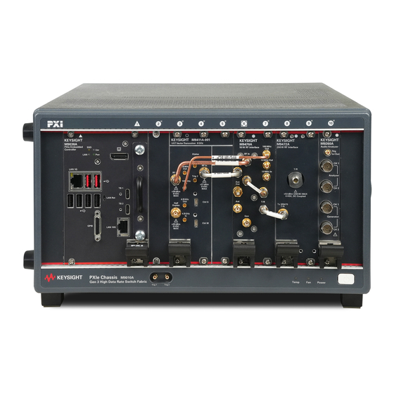
Shipment Contents The Keysight M8920B PXIe Radio Test Set is a multi-module instrument (MMI), housed in a PXIe chassis. This PXIe solution consists of the software, a Keysight M9411A VXT PXIe Vector Transceiver module, a Keysight M9470A PXIe 50 W RF Interface module, a Keysight M9472A PXIe 200 W RF Interface module, and a Keysight M9260A PXIe Audio Analyzer module. -
Page 16: Model Options
Step 2 - Verify Shipment Contents and Model Options Model Options Model - Option List for the M8920B Radio Test Set M8920B Description M8920B-506 Frequency range: 100 kHz to 6 GHz PXIe Radio Test Set M8920B-050 Input power range, 50 W... -
Page 17: Step 3 - Install The Software
Step 3 -Install the Software Step 3 - Install the Software The following topics are found in this chapter: System Requirements (page 18) Power Up the Controller (page 22) Software Installation Overview (page 23) Licensing Options (page 31) Licensing Measurement Application Software (page 35) -
Page 18: System Requirements
8 GB available hard disk space, includes: space 1 GB available for Microsoft .NET Framework 4.6 7 GB available for the M8920B Radio Test Set installation software package Video Support for Direct X 11 graphics with 128 MB graphics memory... -
Page 19: Hardware Requirements
Topic Requirements Chassis PXIe or PXI-H - 7 slots are required (in total) for the M8920B: M9411A (3 slots), M9470A (2 slots), M9472A (2 slots), , and M9260A (1 slot). Controllers A PXI or PXI Express embedded controller or remote controller (external PC connected to the chassis by a PCI-to-PXI interface) is required. -
Page 20: Chassis Requirements
The instruments can operate with mains supply voltage fluctuations up to ±10% of the nominal voltage. M9018B and M9019A chassis air flow The Keysight chassis shown above have multiple air intakes. They are located at the sides, front, and bottom of the chassis. M9010A chassis air flow... - Page 21 Step 3 -Install the Software The Keysight M9010A has two fans on the rear panel. They pull air from the rear panel and push air through the chassis. For more information, go to Keysight.com. Refer to the "Keysight PXIe Chassis Family User Guide"...
-
Page 22: Power Up The Controller
1. Install the embedded controller module into the compatible chassis. The Keysight M9038A PXIe embedded controller and Keysight M9010A chassis for benchtop or Keysight M9019A PXIe chassis for rack mount are recommended. Please refer to the embedded controller and chassis documentation for further details. -
Page 23: Software Installation Overview
Instrument software, which includes the N9093 Radio Test mode application, device drivers (IVI-C, IVI-COM, and LabVIEW G) and the Help files for the Keysight M8920B PXIe Radio Test Set. This software is included with your shipment and is also available at: www.keysight.com/find/M8920B. - Page 24 Step 3 -Install the Software 3. Select Yes to continue with the installation. The installation file will be extracted as shown below. The installer performs a requirements check after extracting. There must be at least 8 GB free space on the C: drive to install the software.
- Page 25 Step 3 -Install the Software If a modular TRX application has been installed on the controller, the installer will uninstall the earlier version first. 5. The VXT InstallShield Wizard appears. Getting Started Guide...
- Page 26 Step 3 -Install the Software The installation includes possible field-programmable gate array (FPGA reprogramming). If the AC power is interrupted during the installation process, it could render the instrument inoperable. Make sure the chassis is plugged into a reliable power source prior to performing the installation. 6.
- Page 27 Step 3 -Install the Software 8. Select Yes, install M9470x and M9260 driver, then select Next. This may take a few minutes. 9. Select Yes, create shortcuts on desktop, then select Next. Getting Started Guide...
- Page 28 Step 3 -Install the Software Once the installation is compete. The LauncherModularTRX shortcut icon will be installed on the Desktop once software installation is finished. Continue with step 10 below. LaunchModular TRX is used to launch modular applications on the VXT module.
- Page 29 Step 3 -Install the Software The progress of the installation is displayed. The installation takes approximately 20 to 30 minutes to complete. During the installation process, some prompt boxes will pop up. If any FPGA versions installed on the installed module are different then what is required by the current modular TRX, the FPGA on that module will be updated.
-
Page 30: Uninstalling The Software
Uninstalling the Software 1. From the Windows Start menu, go to Control Panel, Programs and Features, Uninstall Programs. 2. Scroll down the list of programs and select Keysight X-Series Modular Vector Signal Transceiver. 3. Select Uninstall to begin the process. -
Page 31: Licensing Options
Step 3 -Install the Software Licensing Options The M8920B has four licensing types that have one of two terms attached. The terms are P (Perpetual) and L (1 year). These licensing types and terms are available on all existing measurement applications except the Spectrum Analyzer Measurement Application, which requires a fixed perpetual license (shipped Standard). -
Page 32: Application Licenses
Perpetual or 1 year (12 months), respectively. Example: N9093EM0E-1UP With USB portable licenses, the pre-installed Keysight Floating License Manager used to add licenses to the instrument’s server. USB Portable licenses with a limited count are checked out and in like Network licenses. -
Page 33: Configuring Network And Usb Licenses
Configuring Network and USB Licenses The Keysight Floating License Manager must be used to configure the Network or USB Portable licenses before the licenses can be used. An instrument can be configured for Network or USB Portable licenses or both. -
Page 34: Fixed License Installation Over Usb
4. Connect the USB storage device to one of the controller USB ports. Windows will detect the new hardware and may display the configuration menu. The M8920B will automatically load the license file. (This may take a few minutes.) Upon completion, the Keysight License Manager will display a "Successful License Installation" message. -
Page 35: Trial Licenses
Trial licenses are not installed in the factory and no entitlement certificate are created for distribution with new instrument shipments. Trial licenses are not available to order, but are available from the Keysight Web site after completing a brief registration. -
Page 36: Install License By Using License Manager
Step 3 -Install the Software The M8920B automatically loads the license file. This may take a few minutes. Upon completion, Keysight License Manager displays "Successful License Installation". Alternatively, the license can be manually installed over USB or LAN by placing the license file in the following folder on the controller. - Page 37 Step 3 -Install the Software 5. Enter your myKeysight account login and password, then select Login. 6. In the Install License dialog box, browse to the license file location, select the license file or files and select Open. The install process takes about a minute to complete. 7.
- Page 38 Getting Started Guide...
-
Page 39: Step 4 - Install The Modules
Step 4 - Install the Modules The following topics can be found in this chapter: M8920B Modules (page 40) Module Installation Process Overview (page 40) M8920B Instrument Connections (page 43) M8920B Block Diagram (page 45) Module Front Panel Features (page 45) -
Page 40: M8920B Modules
Step 4 -Install the Modules M8920B Modules The M8920B includes four modules that must be installed: Chassis Slots Part Number Module Name Required M9411A Keysight M9411A VXT PXIe Vector Transceiver module M9470A Keysight M9470A PXIe 50 W RF Interface module... - Page 41 The left-most slot does not accept a slot blocker. 11. If you are using a PCIe cable interface, such as the Keysight M9021A, connect the cable interface in the chassis to the PC host per the instructions that came with the cable interface.
- Page 42 The torque specification for SMA connectors is 8 in-lb (0.904 Nm). 13. Power up the PXIe chassis. 14. If you are using a remote PC, reboot the PC host. 15. Proceed to Step 6 - Verifying Operation of the M8920B (page 69). Getting Started Guide...
-
Page 43: M8920B Instrument Connections
Step 4 -Install the Modules M8920B Instrument Connections This section contains a cabling diagram for the Keysight M8920B PXIe Radio Test Set and a cable and module association table. Refer to Cable and Connector Care (page for proper connector care. For front panel feature descriptions, see the following:... -
Page 44: M8920B Cable And Module Table
Step 4 -Install the Modules If using the M9018B or M9019A 18-slot chassis, the recommended Keysight M8920B PXIe Radio Test Set is configured as follows: Recommended Slot Part Number Module Name Slots Required Location M9038A Embedded controller M9411A VXT PXIe vector transceiver... -
Page 45: Multiple Test Sets In A Single Chassis
Step 4 -Install the Modules Multiple Test Sets in a Single Chassis Only two Keysight M8920B PXIe radio test sets can be installed in a single M9018B or M9019A 18-slot PXIe chassis, sharing a single embedded controller. The recommended multiple configuration for the M8920B Radio Test Set is as follows:... -
Page 46: M9411A Vxt Front Panel Connectors
Step 4 -Install the Modules M9411A VXT Front Panel Connectors The instruments can operate with mains supply voltage fluctuations up to ±10% of the nominal voltage. Getting Started Guide... - Page 47 Trigger source output, 3.3 V into 50 Ω output This trigger is available for the M8920B. Half Duplex Half duplex port for This port is not available to the M8920B. RF input or RF output 4.8 GHz In 4.8 GHz timebase Trigger source output, 3.3 V into 50 Ω...
- Page 48 Input impedance: 1 kΩ or 50 Ω nominal Input level range: -3.3 V to +3.3 V Output impedance: 50 Ω nominal Output level range: 3.3 V LVTTL This trigger is available for the M8920B. Ctrl S Subordinate uHDMI Subordinate uHDMI female connector This trigger is available for the M8920B.
-
Page 49: M9470A Front Panel Connectors
Step 4 -Install the Modules M9470A Front Panel Connectors For parameter limits and specifications on the M9470A connectors, see M8920B Block Diagram (page 45). Image Connector Description This SMA, female 50 Ω nominal connector is the RF receiver input: 100 kHz to 6 GHz. -
Page 50: M9472A Front Panel Connectors
Step 4 -Install the Modules M9472A Front Panel Connectors For parameter limits and specifications on the M9472A connectors, see M8920B Block Diagram (page 45). Image Connector Description This SMA, female 50 Ω nominal connector is the RF transmitter output and receiver input duplexer port: 100 kHz to 6 GHz. -
Page 51: M9260A Front Panel Connectors
Step 4 -Install the Modules M9260A Front Panel Connectors Refer to the Audio Analyzer Data Sheet for the latest updates and more detailed information. https://literature.cdn.keysight.com/litweb/pdf/5992-1918EN.pdf Image Connector Description Trig In/Out This SMB, male connector is the audio measurement trigger input and output common port. -
Page 52: Front And Rear Panel Symbols
Step 4 -Install the Modules Front and Rear Panel Symbols The instruction documentation symbol. The product is marked with this symbol when it is necessary for the user to refer to instructions in the documentation. The CE mark is a registered trademark of the European Community. The RCM mark is a registered trademark of the Australian Spectrum Management Agency. -
Page 53: Step 5 - Launch The Modular Trx Application
Step 5 - Launch the Modular TRX Application Step 5 - Launch the Modular TRX Application This chapter provides the information on how to launch the modular TRX application. Application Launcher (page 54) Launch Features (page 57) Launch the Modular TRX Application (page 65) -
Page 54: Application Launcher
Start Launcher Click to start Launcher from the Desktop. Alternately, you can start the application from the Windows Start menu, All Programs, Keysight Modular Transceiver, LaunchModular TRX. Hardware License Installation Launcher checks if there are any hardware licenses available for the installed modules. - Page 55 Step 5 - Launch the Modular TRX Application The M9470A FPGA automatically updates to the latest version when the VXT software is upgraded. However, you should run FPGA update every time you Launch the TRX application. In the Launch Modular TRX application window, select Show Advanced Settings, then select Run FPGA.
- Page 56 Step 5 - Launch the Modular TRX Application Once the update has completed, turn off the chassis power and turn it back on to enable the update. Getting Started Guide...
-
Page 57: Launch Features
Step 5 - Launch the Modular TRX Application Launch Features The Launch Modular TRX window shows all modules that reside in the chassis. Selected - Specifies which modules are used in for the desired configuration. Chassis Number - When more than one chassis is used, this indicates the chassis location of each module. - Page 58 Step 5 - Launch the Modular TRX Application Run Selected - Runs the Modular TRX on the VXT module. The Launch Type must be either Manual or Auto and the status must be Idle. The configurations are automatically saved in the configure file. Use the Ctrl or Shift keys to select multiple items, or use the mouse or arrow keys to change the selected module.
-
Page 59: Tcp/Ip Address Configuration
2. Select Show Advanced Settings. For the VXT, the HiSLIP Dev value shown is 4. This value will be used to set the remote name in Keysight Connection Expert. Note that you can change the requested HiSLIP port here. If there is a conflict, a new one will automatically be assigned. - Page 60 Step 5 - Launch the Modular TRX Application 3. Select the corresponding checkbox and then select Run Selected to start the application. 4. From the Windows Start menu, run Keysight Connection Expert. a. Select the Manual Configuration tab. b. Set the Hostname or IP Address as localhost.
-
Page 61: Address Setting In Remote Control
1. Find the controller's address by selecting then select Show System Settings. 2. From the Windows Start menu, run Keysight Connection Expert. a. Set the Hostname or IP Address as localhost. b. Set the Hostname or IP Address as localhost. -
Page 62: Hardware License Installation
Prior to shipment from the factory, the hardware license is installed in the module. Use the following procedure to upgrade your hardware license to the latest version. 1. Use Keysight License Manager to install the license file on the controller. Refer Install License by Using License Manager (page 36). - Page 63 Step 5 - Launch the Modular TRX Application 3. Select Install all New HW Licenses. If there are multiple license on multiple modules, all licenses will be installed at the same time. 4. After the hardware license has been installed successfully, the New Hardware licenses column will be empty and the Install All New HW Licenses button will be disabled (grayed out).
- Page 64 Step 5 - Launch the Modular TRX Application Getting Started Guide...
-
Page 65: Launch The Modular Trx Application
Launcher UI is used to launch the Modular TRX Application with one or multiple modules. To launch the M8920B system with the launcher, you need bind the M9470A, M9472A and M9260A modules in advance. Please follwo the steps below to bind the modules. -
Page 66: Launch Modular Trx Application Automatically
Follow the steps below to set preferences for automatic launch of the Modular TRX application: 1. Bind the M9411A module as M8920B with the procedures above. 2. Right click on the desktop Launch ModularTRX icon and select Properties. 3. Select the Shortcut tab and append the Target string with either /Auto or the PXI VISA address of the module. - Page 67 When VISA address is selected, the Modular TRX application is launched for the specified address. The PXI VISA address is shown in the Launch Modular SA window and in Keysight Connection Expert. 4. Select Apply and then OK to save the changes. Every time you start Launcher, the application starts automatically, bypassing the Launch Modular TRX settings window.
- Page 68 Getting Started Guide...
-
Page 69: Step 6 - Verifying Operation Of The M8920B
Step 6 - Verifying Operation of the M8920B Step 6 - Verifying Operation of the M8920B Alignment (page 70) Verify Audio Generation Analysis (page 72) Verify RF Output (page 74) -
Page 70: Alignment
Step 6 - Verifying Operation of the M8920B Alignment Before verifying operation, you should perform an alignment of all subsystems. This should be done, at least once a week any time a module is switched out of the chassis any time a connection change has been made whenever the ambient temperature has change ±5°C... - Page 71 Step 6 - Verifying Operation of the M8920B 4. Select Radio Test Mode, Radio Test Measurement, and Analog Duplex View, then select Okay. 5. Select the (Settings icon) to bring up the System Settings menu. 6. From System Settings, select Alignments, Align Now, Align All Now.
-
Page 72: Verify Audio Generation Analysis
Step 6 - Verifying Operation of the M8920B Verify Audio Generation Analysis 1. On the M9260A PXIe Audio Analyzer module, connect a cable between Ch1 Gen to Ch1 Analyzer. 2. Select the Audio Metrics window to give it the focus. (It will be outlined in blue.) 3. - Page 73 Step 6 - Verifying Operation of the M8920B 5. In the Audio Metrics window, verify that Peak+ is 1.000 V. Getting Started Guide...
-
Page 74: Verify Rf Output
Step 6 - Verifying Operation of the M8920B Verify RF Output 1. Select the RF Spectrum window to give it the focus. 2. In the Measurement panel, select Frequency. Set Center Frequency to 1 GHz, and Span to 1 MHz. - Page 75 Step 6 - Verifying Operation of the M8920B 6. While monitoring the RF Spectrum, vary the RF power level and watch for a corresponding change in signal amplitude. 7. In the Measurement panel, select Peak Search. Make sure the peak power in both the RF Spectrum and RF Generator window>...
- Page 76 Getting Started Guide...
-
Page 77: Step 7 - Installation Is Complete
Step 7 - Installationis Complete Step 7 - Installation is Complete Proceed to program your product by means of the application programming interface (API) for the supplied drivers. The following topics can be found in this chapter: IVI Drivers (page 78) LabVIEW Drivers (page 78) -
Page 78: Api Overview
Base - X-Series Signal Analyzers IVI and MATLAB Instrument Drivers LabVIEW Drivers In addition to the IVI drivers, Keysight provides a LabVIEW driver that includes all the functionality of the IVI-C driver. When you install the product software, the LabVIEW driver is installed to each LabVIEW instr.lib directory for each version of LabVIEW you... - Page 79 .chm file) is also installed with the driver and the content is available from LabVIEW's Context Help window. In addition, you can directly access the chm file (AgM9391 LabVIEW_Help) from this Start menu location:Start > All Programs > Keysight > M9391 > M9391 LabVIEW Help.
- Page 80 Getting Started Guide...
-
Page 81: Troubleshooting
Review the measurement procedures being performed when the problem first appeared. Are all of the settings correct? If the M8920B Radio Test Set solution is not functioning as expected, return it to a known state by selecting , Mode Preset. - Page 82 Troubleshooting http://www.keysight.com/find/M8920B If the M8920B Radio Test Set is not communicating via the LAN connection, check for the presence of blinking yellow LEDs on the rear panel LAN connector. If the ACT LED is not blinking, check the LAN cable and LAN integrity.
-
Page 83: Communications
Troubleshooting Communications If you are unable to communicate with the M8920B verify that the following installations are correct: M8920B software (includes all module drivers) Chassis drivers System interface card, cable and PC PXIe card connections, if you are using an external host PC If all modules and their slot locations are not visible in the SFP "Connect to... -
Page 84: Returning An Instrument For Service
Press System, Show System, and the product numbers, serial numbers, and software revision information will be displayed. Each module has a serial number. The M8920B Radio Test Set has a unique identifier (UID), which is generated automatically from the serial numbers of the individual modules. -
Page 85: Locations For Keysight Technologies
Troubleshooting Locations for Keysight Technologies Online assistance: http://www.keysight.com/find/assist Americas Canada Latin America United States 1 877 894 4414 (305) 269 7500 1 800 829 4444 Asia Pacific Australia China Hong Kong 1 800 629 485 800 810 0189 800 938 693... -
Page 86: Read The Warranty
Service Options Keysight Technologies offers several optional maintenance plans to service your Radio Test Solution after the warranty has expired. Call your Keysight Technologies office for full details. If you want to service the Radio Test Solution yourself after the warranty expires, you can download the service documentation that provides all necessary test and maintenance information from the Keysigt.com. -
Page 87: Packaging The Instrument
Troubleshooting Packaging the Instrument Use original packaging or comparable. It is best to pack the unit in the original factory packaging materials if they are available. Module damage can result from using packaging materials other than those specified. Never use styrene pellets in any shape as packaging materials. - Page 88 Getting Started Guide...
-
Page 89: Cable And Connector Care
Making Connections (page 93) Cleaning Connectors (page 94) Module Cable and Connector Care Use the Keysight cable removal tool to disconnect push-on cables from the module front panel connectors. To avoid damage to the cables or connectors, pull the cable straight away from the connector. -
Page 90: Contact Integrity
Cable and Connector Care Contact integrity Refer to the following for visual guidelines when evaluating the contact integrity of a connector. Concentricity The following examples show the concentricity of both the male and female 1.0 mm connectors: Female connector: Getting Started Guide... -
Page 91: Male Connector
Cable and Connector Care Male connector: Getting Started Guide... -
Page 92: Visual Inspection
Cable and Connector Care Visual Inspection Visual inspection and, if necessary cleaning should be done every time a connection is made. Metal particles from connector threads may fall into the connector when it is disconnected. One connection made with a dirty or damaged connector can damage both connectors beyond repair. -
Page 93: Making Connections
Cable and Connector Care Making Connections Good connections require a skilled operator. Instrument sensitivity and coaxial connector mechanical tolerances are such that slight errors in operator technique can have a significant effect on measurements and measurement uncertainties. The most common cause of measurement error is poor connections. -
Page 94: Cleaning Connectors
Cable and Connector Care Cleaning Connectors 1. Inspect the connectors for dust, dirt, metal fragment, oils or film, and debris. 2. Blow off any dust with a filtered, clean supply of compressed air. 3. Add a few drops of high-purity isopropyl alcohol to a small cleaning swab (do not apply alcohol directly to the parts). - Page 95 This Page Intentionally Left Blank M8920B Getting Started Guide...
- Page 96 This information is subject to change without notice. © Keysight Technologies 2024 Edition 1, April, 2024 M8920-90009 www.keysight.com...
Need help?
Do you have a question about the M8920B and is the answer not in the manual?
Questions and answers