Nibe F1155 Installer Manual
Ground source heat pump
Hide thumbs
Also See for F1155:
- Service manual (108 pages) ,
- User manual (84 pages) ,
- Installer manual (84 pages)
Table of Contents
Advertisement
Quick Links
Download this manual
See also:
User Manual
Advertisement
Table of Contents

Related Manuals for Nibe F1155


Summary of Contents for Nibe F1155
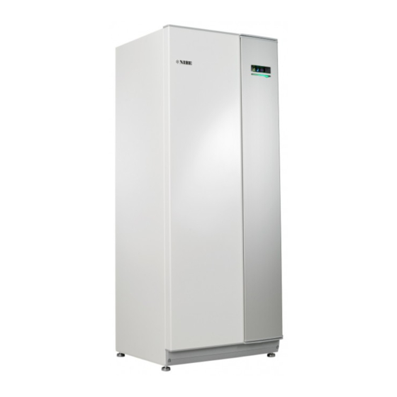
- Page 1 Installer manual NIBE™ F1155 Ground source heat pump IHB GB 1546-6 231565...
- Page 2 Increase hot water volume To temporarily increase the amount of hot water (if a hot water heater is installed to your F1155), first turn the control knob to mark menu 2 (water droplet) and then press the OK button twice.
-
Page 3: Table Of Contents
Docking alternatives Troubleshooting 5 Electrical connections 11 Accessories General Connections 12 Technical data Settings Dimensions and setting-out coordinates Optional connections Technical specifications Connecting accessories Energy labelling 6 Commissioning and adjusting Index Preparations Filling and venting NIBE™ F1155 Table of Contents |... -
Page 4: Important Information
This symbol indicates tips on how to facilitate using the product. Marking The CE marking means that NIBE ensures that the product meets all regulations that are placed on it based on relevant EU directives. The CE mark is obligat- ory for most products sold in the EU, regardless where they are made. - Page 5 Shut off valves Circulation pump setting Electricity (page 20) Connections Main voltage Phase voltage Fuses heat pump Fuses property Outside sensor Room sensor Current sensor Safety breaker Earth circuit-breaker Setting of emergency mode thermostat Miscellaneous NIBE™ F1155 Chapter 1 | Important information...
- Page 6 Description Notes Signature Date ✔ Guarantee submitted Chapter 1 | Important information NIBE™ F1155...
- Page 7 NIBE Energy Systems France Sarl, Zone industrielle RD 28, Rue du Pou du Ciel, 01600 Reyrieux Tel : 04 74 00 92 92 Fax : 04 74 00 42 00 E-mail: info@nibe.fr www.nibe.fr NIBE Energy Systems Ltd, 3C Broom Business Park, Bridge Way, Chesterfield S41 9QG Tel: 0845 095 1200 Fax: 0845 095 1201 E-mail: info@nibe.co.uk www.nibe.co.uk...
-
Page 8: Delivery And Handling
See page 54 for instructions about the separation. Assembly Position F1155 on a firm base that can take the ■ weight, preferably on a concrete floor or foundation. Use the product's adjustable feet to obtain a horizont- al and stable set-up. -
Page 9: Supplied Components
1. Remove the screws from the lower edge of the front cover. 2. Lift the cover out at the bottom edge and up. Particle filter Compression ring couplings F1155 6 kW F1155 6 kW 1 x G1 2 x (ø28 x G25) 1 x G3/4 3 x (ø22 x G20) -
Page 10: The Heat Pump Design
3 The heat pump design General View from behind W130 F1155 QN10 AA4-XJ4 AA4-XJ3 QM34 QM31 QM32 QM33 Chapter 3 | The heat pump design NIBE™ F1155... - Page 11 Display unit AA4-XJ3 USB socket AA4-XJ4 Service outlet (No function) EB 1 Immersion heater SF 1 Switch W 130 Network cable for NIBE Uplink Miscellaneous PF 1 Rating plate PF 2 Type plate, cooling section UB 1 Cable gland, incoming electricity...
-
Page 12: Distribution Boxes
AA 3 Input circuit board AA 23 Communication board FA 1 Miniature circuit-breaker FD 1 Temperature limiter/Emergency mode thermo- stat Designations in component locations according to standard IEC 81346-1 and 81346-2. Chapter 3 | The heat pump design NIBE™ F1155... -
Page 13: Cooling Section
6 kW BT14 BT12 GQ10 QA40 BT10 BT17 AA100 XL20 BT15 BT11 XL21 EB10 3X400V, 16 kW 16 kw BT14 BT17 BT12 GQ10 BT10 QA40 AA100 XL20 BT15 EB10 XL21 BT11 NIBE™ F1155 Chapter 3 | The heat pump design... - Page 14 * Only 16 kW. Cooling components EP 1 Evaporator EP 2 Condenser GQ 10 Compressor HS 1 Drying filter QN 1 Expansion valve Designations in component locations according to standard IEC 81346-1 and 81346-2. Chapter 3 | The heat pump design NIBE™ F1155...
-
Page 15: Pipe Connections
F1155 is not equipped with external shut off valves; compressed in the compressor. The refrigerant, of these must be installed to facilitate any future servicing. -
Page 16: Dimensions And Pipe Connections
Position the vessel so that this does not harm other equipment. Details of the antifreeze used must be shown on the ■ level vessel. * Can be angled for side connection. Chapter 4 | Pipe connections NIBE™ F1155... -
Page 17: Heating Medium Side
Water heater Collector Connecting the hot water heater NOTE If F1155 is not docked to a water heater or if Heating medium side it is to work with fixed condensing, the connec- tion for the water heater (XL9) must be plugged. -
Page 18: Docking Alternatives
Fixed condensing Ground water system If F1155 is to work towards the water heater with fixed An intermediate heat exchanger is used to protect the condensing you must connect an external flow sensor heat pump's exchanger from dirt. The water is released (BT25) according to the description on page 23. - Page 19 Charging of the pool is controlled by the pool sensor. NIBE UKV vessel, e.g. when there is a water coil in the In the case of low pool temperatures, the shuttle valve FTX ventilation.
-
Page 20: Electrical Connections
If the building is equipped with an earth-fault ■ electric additional heat if the temperature exceeds 89°C breaker, F1155 should be equipped with a separate and is reset manually. one. If a miniature circuit breaker is used this should have ■... -
Page 21: Connections
20 cm to high voltage cable when cable routing. Power connection F1155 must be installed with a disconnection option on the supply cable. Minimum cable area must be sized according to the fuse rating used. Enclosed cable for incoming supply electricity is connected to terminal block X1 on the immersion heater board (AA1). - Page 22 Mark up any junction boxes with warnings for external voltage. If you wish to connect external operating voltage for Connection 3x400V the control system to F1155 on the immersion heater circuit board (AA1) the edge connector at AA1:X2 must be moved toAA1:X9 (as illustrated). AA1-X1 Operating voltage (1x230V ~ 50Hz) is connected to AA1:X11 (as illustrated).
- Page 23 BT71 BT71 AA3-X6 Room sensor 1 2 3 4 5 6 7 8 9 F1155 is supplied with a room sensor enclosed (BT50). The room sensor has up to three functions: AA3-X6 F1245 F1155 1. Show current room temperature in F1155's display.
-
Page 24: Settings
Changes of temperature in accommodation take time. For example, short time periods in 3x400V (maximum electrical output, connected combination with underfloor heating will not upon delivery 7 kW for F1155-16) give a noticeable difference in room temperat- Max elec- Max phase... - Page 25 (S2) on the immersion heater – 16.2 board (AA1) according to the table below. The factory 16.2 setting is 3.5 kW for F1155-6 and 6 kW for F1155-16. 16.2 3x400V ((maximum electrical output, connected on delivery to 7 kW) for F1155-16) 3x230V, F1155-6...
-
Page 26: Optional Connections
1x230V and 3x400V for F1155-6 and 3x400V for F1155-16 AA1-SF2 The image shows the dip-switch (AA1-SF2) in the factory setting, i.e. 3.5 kW for F1155-6 and 6 kW F1155-16 . 3x230V for F1155-6 3x230V for F1155-6 AA1-SF2 1x230V for F1155-6 Only 3x230V, the image shows the dip-switch (AA1-SF2) in the factory setting, i.e. - Page 27 This means that when an external switch function or sensor is connected to one of six special connections, the correct function must be selec- ted to the correct connection in the software in F1155. NIBE™ F1155 Chapter 5 |...
- Page 28 SG Ready B), see page 50. An extra temperature sensor (BT74) can be connected Closed or open switch means one of the following: to F1155 in order to determine when it is time to switch ■ between heating and cooling operation.
- Page 29 An external contact function can be connected to potential-free switch function to the input selected in F1155 for activation of one of the four fan speeds. The menu 5.4, see page 50. switch must be potential free and connected to the A closed switch results in blocked heating operation.
-
Page 30: Connecting Accessories
(230V ~). Connecting accessories Instructions for connecting accessories are in the install- ation instructions provided for the respective accessory. See information at www.nibe.eu for the list of the ac- cessories that can be used with F1155. Chapter 5 | Electrical connections... -
Page 31: Commissioning And Adjusting
Preparations brine system's filler connector as illustrated. 3. If alternative 1 (level vessel) is used, close the valve 1. Ensure that F1155 has not been damaged during under the level vessel (CM2). transport. 4. Close the three way valve in the filler connector 2. -
Page 32: Start Guide
Name and menu number Read what menu in the control system this page of the If the building is cooled when F1155 starts, the com- start guide is based on. The digits in brackets refer to pressor may not be able to meet the entire demand the menu number in the control system. -
Page 33: Post Adjustment And Venting
(see page 45) and deactivate "auto" and set the pump's To set the correct flow in the brine system, the brine speed according to the diagram below. P80% pump must run at the correct speed. F1155 has a brine pump that can be automatically controlled in standard Caution F1145 100% mode. - Page 34 Tillgängligt tryck, kPa / Eleffekt, W Heating medium side Readjusting, venting, collector side P100% F1155 has a heating medium that is automatically Level vessel controlled. If a manual speed is required, open menu 5.1.11 (see page 46) and deactivate "auto" and set the Check the fluid level in the level vessel pump's speed according to the diagram below.
-
Page 35: Setting The Cooling/Heating Curve
1. Select the climate system (if more than one) for which the curve is to be changed. 2. When the climate system selection has been con- firmed, the curve number is marked. NIBE™ F1155 Chapter 6 | Commissioning and adjusting... - Page 36 If it is warm outdoors and the room temperat- ure is too low, increase the curve offset by one increment. If it is warm outdoors and the room temperat- ure is too high, lower the curve offset by one increment. Chapter 6 | Commissioning and adjusting NIBE™ F1155...
-
Page 37: Control - Introduction
The control knob can be turned to the right or left. You can: ■ scroll in menus and between options. ■ increase and decrease the values. ■ change page in multiple page instructions (for example help text and service info). NIBE™ F1155 Chapter 7 | Control - Introduction... -
Page 38: Menu System
4.7. formation in the help menu or user manual. This menu only appears if a water heater is docked to This symbol indicates whether F1155 has the heat pump. contact with NIBE Uplink™. Menu 3 - INFO... - Page 39 To select another option: 1. Mark the applicable option. One of the options is pre-selected (white). 2. Press the OK button to confirm the selected option. The selected option has a green tick. NIBE™ F1155 Chapter 7 | Control - Introduction...
- Page 40 (at the page number) has been marked. 2. Press the OK button to skip between the steps in the start guide. If the start guide is left on this page it closes automatically in 60 min Chapter 7 | Control - Introduction NIBE™ F1155...
-
Page 41: Control - Menus
Menu 3 - INFO 3 - INFO 3.1 - service info 3.2 - compressor info 3.3 - add. heat info 3.4 - alarm log 3.5 - indoor temp. log * Accessories are needed. NIBE™ F1155 Chapter 8 | Control - Menus... -
Page 42: Menu 4 - Heat Pump
Menu 4 - HEAT PUMP 4 - HEAT PUMP 4.1 - plus functions 4.1.1 - pool * 4.1.3 - internet 4.1.3.1 - nibe uplink 4.1.3.8 - tcp/ip settings 4.1.3.9 - proxy settings 4.1.4 - sms * 4.1.5 - SG Ready 4.1.6 - smart price adaption... -
Page 43: Menu 5 - Service
Operational settings for different Operating settings can be made for the heat pump in accessories. the sub menus. soft in/outputs Setting software controlled in and outputs on the input circuit board (AA3). NIBE™ F1155 Chapter 8 | Control - Menus... - Page 44 1. is required) normal and speed 1-4 Setting range: 0 – 100 % Set the speed for the five different selectable speeds for the fan here. Chapter 8 | Control - Menus NIBE™ F1155...
- Page 45 The heating medium pump runs according to the current operating mode for F1155. intermittent: The heating medium pump starts approx. 20 seconds before and stops at the same time as the compressor.
- Page 46 (accessory is required) Here you set the max. electrical output of the internal Setting range: 1 - 100 % electrical addition in F1155 and the fuse size for the Default values: 70 % installation. Here you can also check which current sensor is in-...
- Page 47 If the water heater is docked to F1155 hot water char- months btwn filter alarms: Set how many months ging must be activated here.
- Page 48 Setting range: on/off Factory setting: off mixing valve amplifier Setting range: 0.1 – 10.0 Default value: 1.0 mixing valve step delay Setting range: 10 – 300 s Default values: 30 s Chapter 8 | Control - Menus NIBE™ F1155...
- Page 49 (BT53) and the temperature of the brine in the heat pump (BT10) is less than this set- ting the function deactivates. See the accessory installation instructions for function description. NIBE™ F1155 Chapter 8 | Control - Menus...
- Page 50 Default value: 55 °C mixing valve amplifier Setting range: 0.1 – 10.0 Default value: 1.0 mixing valve step delay Setting range: 10 – 300 s Default values: 30 s Chapter 8 | Control - Menus NIBE™ F1155...
- Page 51 0 days. Mark the active window to activate the underfloor drying function. A counter at the bottom shows the number of days the function has been active. The NIBE™ F1155 Chapter 8 | Control - Menus...
-
Page 52: Service
Emergency mode NOTE The switch (SF1) must not be moved to " " or " " until F1155 has been filled with water. Component parts in the product can be dam- aged. Emergency mode is used in event of operational inter- ference and in conjunction with service. - Page 53 6. Screw in the venting screw (QM5). Draining the entire climate system 7. Start F1155 by setting the switch (SF1) to " " and If the entire climate system requires draining, do this check whether the circulation pump works.
- Page 54 Remove the front cover according to the de- scription on page 9. Close the shut-off valves (QM31), (QM32), (QM33) F1255 and (QM34). Drain the compressor module according to the in- structions on page 52 QM31 QM33 F1255 QM34 QM32 Chapter 9 | Service NIBE™ F1155...
- Page 55 Disconnect the connectors (A) and (B) from the underside of the base card cabinet. QM34 QM32 Disconnect the connector (C) from the immersion heater circuit board (AA1) using a screwdriver. Disconnect the connector (D) from the joint circuit board (AA100). NIBE™ F1155 Chapter 9 | Service...
- Page 56 This allows you to update the software in F1155. NOTE F1155 is equipped with a USB socket in the display unit. For the following functions to work the USB This USB socket can be used to connect a USB memory...
- Page 57 Setting range: 1 s – 60 min Factory setting range: 5 s Here you can choose how current measurement values from F1155 should be saved onto a log file on the USB memory. 1. Set the desired interval between loggings.
-
Page 58: Disturbances In Comfort
This can mean that the heat pump's compressor is not running. In this case the immersion heater produces heat and/or hot water. NOTE To select aid mode an alarm action must be selected in the menu 5.1.4. Chapter 10 | Disturbances in comfort NIBE™ F1155... - Page 59 ■ This part of the fault-tracing chapter only applies if the heating curve up. If the room temperature is only NIBE FLM accessory is installed. low in cold weather the curve slope in menu 1.9.1 "heating curve" needs adjusting up.
-
Page 60: Accessories
An accessory card is also required if the ground water Immersion heater pump or external circulation pump is connected to 5 kW, 1 x 230 V F1155 at the same time that the buzzer alarm is activ- Part no. 069 025 ated. Part no. 067 060... - Page 61 Part no. 083 015 Part no. 067 064 VPB 500 Solar 40 Copper lined water heater with charge coil Solar 40 means that F1155 (together with VPAS) can be connected to solar heating. Part no. 083 220 Part no. 067 084 VPAS 300/450...
-
Page 62: Technical Data
Dimensions and setting-out coordinates * This dimension applies at 90° angle on the brine pipes (side connection). The dimension can vary approx. ±100 mm in height as the brine pipes partially consist of flexible pipes. Chapter 12 | Technical data NIBE™ F1155... -
Page 63: Technical Specifications
230V 3 ~ 50Hz Max operating current including 0 – 1 kW immersion heater (Recommended fuse rating). 16(16) Max operating current including 1.5 – 4.5 kW immersion heater (Recommended fuse rating). 20(20) Additional power 0.5/1/1.5/2/2.5/3 /3.5/4/4.5 NIBE™ F1155 Chapter 12 | Technical data... - Page 64 Ssc equal to or greater than 2.0 MVA. Chapter 12 | Technical data NIBE™ F1155...
- Page 65 Min system pressure brine 0.05 (0.5 bar) Nominal flow (50 Hz) 0.18 0.51 Max external avail. press at nom flow Max/Min incoming Brine temp °C see diagram Min. outgoing brine temp. °C Heating medium circuit NIBE™ F1155 Chapter 12 | Technical data...
- Page 66 065 275 065 260 Part number, 3x400V 065 294 065 295 Reported efficiency for the system takes the product's temperature regulator into account. With feet removed the height is approx. 1650 mm for F1155. Chapter 12 | Technical data NIBE™ F1155...
- Page 67 Angiven värmeeffekt This diagram shows the working range below 75 % for Arbetsområde under 75% för F1155-1255 6kW och för hela arbetsområdet 16 kW. F1155-6 and the entire working range for F1155-16. Arbetsområde under 75% för F1155-1255 6kW och för hela arbetsområdet 16 kW.
- Page 68 Framledningstemp. Värmebärare 35 °C för F1155-1255 -6 kW. Framledningstemp. Värmebärare 50 °C för F1155-1255 -6 kW. Angiven värmeeffekt Angiven värmeeffekt Supply temperature, heating medium 35 °°C Supply temperature, heating medium 50 °°C 100% F1155-6 F1155-6 Framledningstemp. Värmebärare 35 °C för F1155-1255 -6 kW.
-
Page 69: Energy Labelling
Energy labelling Information sheet Supplier NIBE AB Model F1155-6 1x230V Model hot water heater VPB 300 Temperature application °C 35 / 55 Declared load profile for water heating Seasonal space heating energy efficiency class, average A++ / A++ climate Water heating energy efficiency class, average climate... - Page 70 Supplier NIBE AB Model F1155-6 3x230V Model hot water heater VPB 300 Temperature application °C 35 / 55 Declared load profile for water heating Seasonal space heating energy efficiency class, average A++ / A++ climate Water heating energy efficiency class, average climate...
- Page 71 Supplier NIBE AB Model F1155-6 3x400V F1155-16 3x400V Model hot water heater VPB 300 VPB 300 Temperature application °C 35 / 55 35 / 55 Declared load profile for water heating Seasonal space heating energy efficiency class, average A++ / A++...
- Page 72 Data for energy efficiency of the package Model F1155-6 1x230V Model hot water heater VPB 300 Temperature application °C 35 / 55 Controller, class Controller, contribution to efficiency Seasonal space heating energy efficiency of the pack- 204 / 154 age, average climate...
- Page 73 Technical documentation Model F1155-6 1x230V Model hot water heater VPB 300 Type of heat pump Air-water Exhaust-water Brine-water Water-water Low-temperature heat pump Integrated immersion heater for additional heat Heat pump combination heater Climate Average Cold Warm Temperature application Average (55 °C) Low (35 °C)
- Page 74 Model F1155-6 3x230V Model hot water heater VPB 300 Type of heat pump Air-water Exhaust-water Brine-water Water-water Low-temperature heat pump Integrated immersion heater for additional heat Heat pump combination heater Climate Average Cold Warm Temperature application Average (55 °C) Low (35 °C) Applied standards EN-14825 &...
- Page 75 Model F1155-6 3x400V Model hot water heater VPB 300 Type of heat pump Air-water Exhaust-water Brine-water Water-water Low-temperature heat pump Integrated immersion heater for additional heat Heat pump combination heater Climate Average Cold Warm Temperature application Average (55 °C) Low (35 °C) Applied standards EN-14825 &...
- Page 76 Model F1155-16 3x400V Model hot water heater VPB 300 Type of heat pump Air-water Exhaust-water Brine-water Water-water Low-temperature heat pump Integrated immersion heater for additional heat Heat pump combination heater Climate Average Cold Warm Temperature application Average (55 °C) Low (35 °C) Applied standards EN-14825 &...
-
Page 77: Index
Contact for activation of fan speed, 29 Load monitor, 26 Contact for activation of “external adjustment", 29 Miniature circuit-breaker, 20 Contact for activation of “temporary lux", 29 NIBE Uplink™, 27 Contact for external tariff blocking, 28 Optional connections, 26 Contact information, 7 Outdoor sensor, 23... - Page 78 Use the virtual keyboard, 40 USB service outlet, 56 Miniature circuit-breaker, 20 Setting a value, 39 Settings, 24 Standby mode, 52 NIBE Uplink™, 27 Power in emergency mode, 25 NV 10, pressure/level/flow monitor brine, 29 Start guide, 32 Status lamp, 37 OK button, 37...
- Page 79 Component location electrical cabinets, 12 Component locations, 10 List of components, 10 Transport, 8 Troubleshooting, 58 USB service outlet, 56 Use the virtual keyboard, 40 Working range heat pump, 67 NIBE™ F1155 Chapter 13 | Item register...
- Page 84 WS name: Anders WS version: a5 (working edition) Publish date: 2015-11-11 16:21 NIBE AB Sweden Hannabadsvägen 5 Box 14 SE-285 21 Markaryd info@nibe.se www.nibe.eu 231565...
Need help?
Do you have a question about the F1155 and is the answer not in the manual?
Questions and answers