Table of Contents
Advertisement
Quick Links
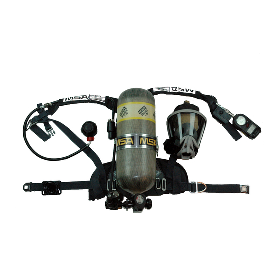
MMR™ Air Mask
MSA 2002 Edition
UPGRADE INSTRUCTIONS
Installation of this upgrade kit will provide the functionality intended by the NFPA
1981-2002 Edition Standard, however the air mask cannot be considered NFPA 2002
Edition Compliant, since the NFPA 1981-2007 Edition Standard is currently in effect.
For new air mask or upgrades, the NFPA only recognizes compliance to the current
edition of the standard.
This manual must be carefully read and followed by all persons who have or will have
the responsibility for using or servicing this air mask. This air mask will perform as
designed only if used and serviced according to the instructions; otherwise it could fail
to perform as designed, and persons who rely on the air mask could sustain serious
personal injury or death.
DO NOT use a 2216psi air cylinder on a 3000psi operating system. Such a configura-
tion is not approved by NIOSH. Failure to follow this warning can result in serious per-
sonal injury or death.
The NightFighter™ Heads-Up Display System complies with Part 15 of the FCC
Rules.
Operation is subject to the following conditions:
(1) This device may not cause harmful interference and
(2) This device must accept any interference that may cause
undesired operation.
Changes and modifications not expressly approved by the manufacturer could
void the User's authority to operate the equipment.
The warranties made by MSA with respect to the product are voided if the prod-
uct is not installed, used and serviced in accordance with the instructions in this
manual. Please protect yourself and your employees by following the instructions.
Please read and observe the WARNINGS and CAUTIONS inside. For any additional
information relative to use or repair, write or call 1-800-MSA-2222 during regular
working hours.
TAL 801 (L) Rev. 5
NOTICE
© MSA 2008
Prnt. Spec. 10000005389(A)
Mat. 10039500
Doc. 10000014102
Advertisement
Table of Contents

Related Manuals for MSA MMR


Summary of Contents for MSA MMR
- Page 1 Changes and modifications not expressly approved by the manufacturer could void the User’s authority to operate the equipment. The warranties made by MSA with respect to the product are voided if the prod- uct is not installed, used and serviced in accordance with the instructions in this manual.
-
Page 2: Table Of Contents
Failure to follow this warning can result in manual. Only trained or certified personnel, authorized serious personal injury or death. by MSA, are permitted to maintain and repair this apparatus. Breathing apparatus must not be repaired beyond the manufacturer's recommendations. 29 CFR Part 1910.134, Par. -
Page 3: Inspection
1. Don the air mask following the original instructions Z88.5, describe three levels of inspection procedures that provided by MSA. These steps make up the air mask are to be performed. Refer to these documents or to an functional test. - Page 4 Inspect all harness and carrier components for cuts, tears, abrasions, or signs of heat or chemical-relat- ed damage. Check that tee nuts, washers, and Only MSA-Certified Technicians are authorized to screws are secured. install the Upgrade Kit. b. Inspect the cylinder band and latch to be sure it holds the cylinder securely.
-
Page 5: Nightfighter™ Heads-Up Display System Bracket And Transmitter Kit
3. Unthread and remove the adapter assembly. The NightFighter Heads-Up Display System Bracket and Transmitter Kit is designed to attach to an MSA Ultra Elite Facepiece to allow the easy attachment and removal of Be careful that you do not damage internal parts of the NightFighter Heads-Up Display System. - Page 6 NOTES TAL 801 (L) Rev. 5 - 10039500...
-
Page 7: Installation Of Receiver Bracket And Cover
Tighten firmly. transmitter only) 6. Verify each of the following features: • MMR with ICM Unit 2000/ICM Unit 2000 Plus installed a. The adapter bayonets are locked into a horizontal (NightFighter transmitter only) position and CANNOT be rotated. - Page 8 Note: If AIR MASK does not have the Quick-Fill System option installed on the over-the-shoulder gauge line hose, Only MSA-certified technicians are authorized to remove the gauge from the MMR harness gauge hose. install the Upgrade Kit. 1. Close the bypass valve fully.
-
Page 9: Removing The Icm Unit
DISASSEMBLY REMOVING PRESSURE GAUGE OR REDUNDANT 1. Using wrenches. Unthread and remove the existing ALARM Quick-Fill System block and pressure gauge from the gauge hose fitting. 2. Using the o-ring removal tool. Remove the o-ring and back-up ring from the end of the gauge hose fitting. Note: Salvage the quick-fill system (male) coupling from the existing block. - Page 10 DISASSEMBLY 1. Use a wrench to hold the quick-fill system block or place quick-fill system block in a vise using protective DO NOT re-use the OLD jam nut. Dispose of it imme- sleeves to keep from damaging the block. diately. Failure to follow this warning could result in 2.
-
Page 11: Installing The Transmitter On The Gauge Line
INSTALLATION INSTALLING THE TRANSMITTER ON THE GAUGE LINE CLEANING 1. Apply alcohol to a Q-Tip applicator. 1. Apply a thin film of Christo-Lube Lubricant to a new a. Wipe the threads on the pressure gauge or the ICM back-up ring. Place the back-up ring in the groove on Unit and the wipe jam nut (dull surface finish). - Page 12 INSTALLATION INSTALLATION OF PRESSURE GAUGE OR ICM UNIT DO NOT tighten the gauge by hand. Use wrenches. Note: Prior to applying Loctite ensure the threads on the pressure gauge or ICM Unit are wiped clean. 1. Apply Loctite 271 on two threads approximately a Use only gauges (P/N 10003610, P/N 10003611 or tenth (0.10) of an inch from the thread shoulder of the 3000psi gauge P/N 10047235) with a straight thread.
- Page 13 INSTALLATION INSTALLING THE QUICK-FILL COUPLING IN THE Note: The quick-fill system coupling can only be salvaged TRANSMITTER ADAPTER PORT by installing into Audi-Larm for 3000psi Operating System air mask. Refer to Removing the Quick-Fill System Adapter Block section. 1. Place the transmitter block in a vise. Use protective sleeves to keep from damaging the block.
- Page 14 NOTES TAL 801 (L) Rev. 5 - 10039500...
-
Page 15: Leak Testing
LEAK TESTING Over-the-shoulder quick-fill system configuration is DO NOT use a 2216psi Air Cylinder on a 3000psi not compatible with the 3000psi Operating System Air Operating System. Such a configuration is not Mask. Failure to follow this warning can result in seri- approved by NIOSH. - Page 16 NOTES TAL 801 (L) Rev. 5 - 10039500...
-
Page 17: Upgrading Instructions For Urc Assembly (Universal Rescue Connection)
The inspection and maintenance procedures authorized in P/N 10037954. this manual are classified User Maintenance. Additional, advanced training is available. Contact your MSA repre- All repair procedures assume that the Audi-Larm Audible sentative for details. Refer to the appropriate Illustrated Alarm is disassembled from the cylinder. - Page 18 UPGRADING INSTRUCTIONS b. Place a wrench on the hex flats of the hose fitting. b. Clamp the URC Assembly body in a vise. Remove Unthread in a counter-clockwise direction to remove tape from hose threads. the high pressure hose. c. Using the o-ring removal tool, remove the o-ring from the hose fitting.
- Page 19 1. Turn carrier and harness assembly so cylinder band faces down. MSA logo (on back plate) is on left side. 5. Re-attach back pad to carrier with the old screws, 2. Ensure area is clean.
Need help?
Do you have a question about the MMR and is the answer not in the manual?
Questions and answers