Table of Contents
Advertisement
Quick Links
Advertisement
Table of Contents

Related Manuals for Rotabroach Falcon RP05520/4


Summary of Contents for Rotabroach Falcon RP05520/4
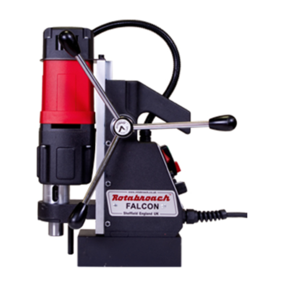
- Page 1 FALCON MAGNETIC DRILLING MACHINE Model No. RP05520/4 RIVVAL LTD, Registered Office: RIVVAL Ltd., Oakdale, Carrickasedge, Carrickmacross, Co. Monaghan, Ireland. Tel: +353 42 969 0882 Web: www.rivval.com Email: sales@rivval.com Company Number: 390186 VAT Number: 6410186G ...
-
Page 3: Table Of Contents
Issue 1 Original Version January 2012 Contents Page Genral safety Machine Specification Machie operation Safety Machine Operation instructions Chuck instalation Speed Selection Mounting of cutters Remedies for hole making problems Trouble shooting Exploded diagram of machine Exploded diagram of motor Maintenance checks Cutter selection and speed and feed information Warranty... -
Page 4: Genral Safety
Issue 1 Original Version January 2012 1) GENERAL SAFETY RULES WARNING! When using electric tools basic safety precautions should always be followed to reduce the risk of fire, electric shock and personal injury, including the following. Read all these instructions before attempting to operate this product Remove the power supply before carrying out any adjustment, serving or maintenance. -
Page 5: Machine Specification
Issue 1 Original Version January 2012 2) Specification Maximum hole cutting capacity in .2/.3C steel = 50mm dia. x 50mm deep Arbor bore = 19.05mm (3/4”) dia. Motor Unit CM/405/1 110V 11.5A, 1150W CM/405/3 230V 5.75A, 1150W Overall Machine 230 x 160 x 420mm Dimensions Magnet Footprint 170mm x 85mm... -
Page 6: Machie Operation Safety
Apply light pressure when commencing to cut a hole until the cutter is introduced into the work surface. Pressure can then be increased sufficiently to load the motor. Excessive pressure is undesirable when using the Rotabroach “FALCON” machine. It does not increase the rate of penetration and may result in damage to the machine and cutter. -
Page 7: Chuck Instalation
Arbors for cutters Currently available from Rotabroach are a number of various Arbors for fitting our range of cutters that are available with the standard 19.05mm Weldon shank attachment and also are available with a 32mm Weldon shank. -
Page 8: Mounting Of Cutters
Issue 1 Original Version January 2012 MOUNTING OF CUTTERS The machine has been made to accept cutters having 19.05mm (3/4”) dia. shanks. The following procedure is to be used when mounting cutters. • Lay the machine on its side with feed handles uppermost, ensuring arbor is wound down to its lowest point to enable access to socket screws. -
Page 9: Trouble Shooting
Issue 1 Original Version January 2012 9) TROUBLE SHOOTING Magnet and motor do not function - The magnet switch is not connected to the power supply - Damaged or defective wiring - Defective fuse - Defective magnet switch - Defective Control Unit - Motor forward/reverse switch set to O Magnet does function, the motor does not - Damaged or defective wiring... -
Page 10: Exploded Diagram Of Machine
Issue 1 Original Version January 2012 10) MACHINE ASSEMBLY Component identification for CM/405/1-3 FALCON Item No Part No Description. Item No Part No Description. RD48153 Frame RD48196 Screw+washer+nut RD48174 Screw SSM6x16 RD38001 Info Plate RD48175 Washer M6 RD48198 Panel screw M4x8 (rearplate) Panel screw long M4x20 RD48176 Setting Nut... -
Page 11: Exploded Diagram Of Motor
Issue 1 Original Version January 2012 11) MOTOR ASSEMBLY Component identification for CM/405/1-3 FALCON Item No Part No Description. Item No Part No Description. RD48215 Screw 3,9x60 RD48236 End cover RD48216 Adaptor ring 22x0,2 RD48237 Housing RD48217 Needle bearing RD48238 Circlip 471/10 RD48218 Bearing 8x22x7... -
Page 12: Maintenance Checks
January 2012 12) Tips for keeping your machine in correct working order. In order to ‘get the best life’ out of your Rotabroach machine always keep in good working order. A well maintained machine is a happy machine. A number of items must always be checked on Rotabroach machines. - Page 13 Issue 1 Original Version January 2012 Adjustment of slide and bearing bracket Alignment. An essential requirement of the machine is that the slide can move in a smooth and controlled manner, free of lateral movement and vibration. This situation can be maintained by periodic adjustment of the slide and is accomplished in the following manner: 1.
-
Page 14: Cutter Selection And Speed And Feed Information
Issue 1 Original Version January 2012 13) Cutter selection, Speeds and Feeds... - Page 15 Issue 1 Original Version January 2012 Notes...
-
Page 16: Warranty
Rotabroach®, or its designated distributor within a period of (30) days from the purchase date, failure to do so will void the warranty. If the stated is adhered to Rotabroach® will repair or replace (at its option) without charge any faulty items returned.
Need help?
Do you have a question about the Falcon RP05520/4 and is the answer not in the manual?
Questions and answers