GESTRA NRGT 26-2 Original Installation & Operating Manual
Level transmitter
Hide thumbs
Also See for NRGT 26-2:
- Original installation & operating manual (44 pages) ,
- Original installation & operating manual (52 pages) ,
- Original installation & operating manual (60 pages)

Related Manuals for GESTRA NRGT 26-2


Summary of Contents for GESTRA NRGT 26-2
- Page 1 Level Transmitter NRGT 26-2 NRGT 26-2s Original Installation & Operating Manual 819876-00 E n g l i s h...
-
Page 2: Table Of Contents
Installing the NRGT 26-2s ........................29 Installation example with dimensions for the NRGT 26-2 ................30 Positioning the terminal box ........................35 Functional elements of the NRGT 26-2 / NRGT 26-2s ................. 36 NRGT 26-2, NRGT 26-2s - Installation & Operating Manual - 819876-00... - Page 3 Taking out of service ............................ 52 Cleaning the measuring electrode of the level transmitter ................ 53 Cleaning interval ............................53 Disposal ................................ 53 Returning decontaminated equipment ......................53 EU Declaration of Conformity ........................54 NRGT 26-2, NRGT 26-2s - Installation & Operating Manual - 819876-00...
-
Page 4: Content Of This Manual
■ ■ 1 x Installation & Operating Manual ■ ■ Required accessories for NRGT 26-2 and NRGT 26-2s when installing for the first time 1 x cable jack, Hirschmann ELWIKA 5012 ■ ■ NRGT 26-2, NRGT 26-2s - Installation & Operating Manual - 819876-00... -
Page 5: How To Use This Manual
How to use this Manual This Installation & Operating Manual describes the correct use of NRGT 26-2 and NRGT 26-2s level trans- mitters. It applies to persons who integrate this equipment in control systems, install, bring into service, operate, maintain and dispose of this equipment. Anyone carrying out the above-mentioned activities must have read this Installation &... -
Page 6: Types Of Warning
Warning of a dangerous situation that may possibly result in death or serious injury. CAUTION Warning of a situation that may result in minor or moderate injury. ATTENTION Warning of a situation that results in damage to property or the environment. NRGT 26-2, NRGT 26-2s - Installation & Operating Manual - 819876-00... -
Page 7: Specialist Terms/Abbreviations
A boiler that is operated at 10 bar and 180°C may be designed for a pressure of 60 bar and a temperature of 275 °C, for example, which is not necessarily its operating point. NRGT 26-2, NRGT 26-2s - Installation & Operating Manual - 819876-00... -
Page 8: Usage For The Intended Purpose
(Er = 80), it may be necessary to adjust the measuring frequency. For this, please contact the GESTRA AG Service department. Applicable directives and standards NRGT 26-2 and NRGT 26-2s level transmitters have been tested and approved for use in the scope gov- erned by the following directives and standards: Directives:... -
Page 9: Admissible System Components, Dependent On The Required Safety Level
Do not use the equipment in potentially explosive atmospheres. Do not bring any equipment into service that does not have its own specific name plate. The name plate indicates the technical features of the equipment. NRGT 26-2, NRGT 26-2s - Installation & Operating Manual - 819876-00... -
Page 10: Basic Safety Notes
Check that the system is not carrying live voltage before commencing work. ■ ■ Danger to life from a faulty NRGT 26-2 or NRGT 26-2s level electrode due to the sudden escape of hot steam or hot water. Shocks and impacts during transport or installation can result in damage to or leaks in the level electrode, causing pressurised hot steam or hot water to escape through the pressure relief hole. -
Page 11: Required Personnel Qualifications
Specialist staff with pressure and temperature. Fig. 1 Notes on product liability We the manufacturer cannot accept any liability for damages resulting from improper use of the equip- ment. NRGT 26-2, NRGT 26-2s - Installation & Operating Manual - 819876-00... -
Page 12: Functional Safety, Safety Integrity Level (Sil)
Functional safety, safety integrity level (SIL) NRGT 26-2 and NRGT 26-2s level transmitters have a secure 4-20 mA actual value output (SIL 2). If an electronic control unit that also has a SIL 2 rating is connected to the 4-20 mA output, the entire event chain system can be operated at this safety integrity level. -
Page 13: Reliability Data To En 61508
Fraction of undetected dangerous failures that beta = 2 % have a common cause Fraction of detected dangerous failures that beta d = 1 % have a common cause Fig. 2 NRGT 26-2, NRGT 26-2s - Installation & Operating Manual - 819876-00... -
Page 14: Function
A protective tube provided on site ensures reliable function (see page 30 “Installation examples”). A capacitive NRGT 26-2 or NRGT 26-2s level transmitter and a conductive NRG 1x-60 or NRG 1x-61 level electrode can be installed in the same protective tube or level pot. - Page 15 Every time there is a fault, 0 mA is displayed via the current output. Electrode faults cannot be acknowledged. When the fault is corrected, the message disappears from the display, and the NRGT 26-2 or NRGT 26-2s level transmitter returns to normal operation.
-
Page 16: Technical Data
Max. installed length: 1053 Measuring range: Max. installed length: 1157 1262 1366 1471 1579 2099 Measuring range: 1075 1175 1275 1375 1475 1975 Do not shorten the electrode rod. NRGT 26-2, NRGT 26-2s - Installation & Operating Manual - 819876-00... - Page 17 1 x rotary knob IP65 with button for menu navigation and test function ■ ■ Protection class III Safety Extra Low Voltage (SELV) ■ ■ IP rating to EN 60529 IP 65 ■ ■ NRGT 26-2, NRGT 26-2s - Installation & Operating Manual - 819876-00...
- Page 18 Admissible installation positions Vertical ■ ■ Oblique to a maximum inclination of 45°. In this case, the length of the electrode rod is ■ ■ limited to 688 mm maximum. NRGT 26-2, NRGT 26-2s - Installation & Operating Manual - 819876-00...
-
Page 19: Name Plate/Identification Of Nrgt 26-2
Manufacturer Disposal information Münchener Str. 77 28215 Bremen GERMANY Protection class Serial number Fig. 3 The date of production is stamped on the screw-in body of the level transmitter. NRGT 26-2, NRGT 26-2s - Installation & Operating Manual - 819876-00... -
Page 20: Name Plate/Identification Of Nrgt 26-2S
Manufacturer Disposal information Münchener Str. 77 28215 Bremen GERMANY Protection class Serial number Fig. 4 The date of production is stamped on the screw-in body of the level transmitter. NRGT 26-2, NRGT 26-2s - Installation & Operating Manual - 819876-00... -
Page 21: Factory Settings
Factory settings NRGT 26-2 and NRGT 26-2s level transmitters are delivered ex-works with the following settings. Menu display Parameter values Unit Raw value (hex) CAL.L Variable approx. 50 mV on ADC CAL.P Variable 25 % Raw value (hex) Raw value (hex) CAL.H... -
Page 22: Overall View Of The Nrgt 26-2
Sheath (simplified view) Seal seat for sealing ring Sealing ring D 27 x 32, form D, DIN 7603-2.4068, bright annealed Electrode thread Electrode Electrode rod insulation PTFE Fig. 6 NRGT 26-2, NRGT 26-2s - Installation & Operating Manual - 819876-00... -
Page 23: Overall View Of The Nrgt 26-2S
43 Cover screws M4 x 16 mm M12 connector, 5-pole, A-coded Sheath (simplified view) Flange DN 50, PN 40, DIN 1092-01 Protective tube Electrode Spacer disc Fig. 7 NRGT 26-2, NRGT 26-2s - Installation & Operating Manual - 819876-00... -
Page 24: Dimensions Of The Nrgt 26-2
238 °C Ø 15 1004 1110 1000 1214 1100 1319 1200 1423 1300 1528 1400 1636 1500 Fig. 8 All lengths and diameters 2156 2000 in mm NRGT 26-2, NRGT 26-2s - Installation & Operating Manual - 819876-00... -
Page 25: Dimensions Of The Nrgt 26-2S
Ø 48.5 range at 238 °C 1053 1157 1075 Ø 42.5 1262 1175 1366 1275 1471 1375 1579 1475 Fig. 9 All lengths and diameters 2099 1975 in mm NRGT 26-2, NRGT 26-2s - Installation & Operating Manual - 819876-00... -
Page 26: Preparing For Installation
The NRGT 26-2s is delivered ex-works with flange and protective tube already fitted. The flange must ■ ■ be secured on site with M16 screws. Required size = AF24. NRGT 26-2, NRGT 26-2s - Installation & Operating Manual - 819876-00... -
Page 27: Installation
The level electrode may (only if inserted in a two-hole flange) be installed with a maximum inclination of - 45°, and the electrode rod is then limited to 688 mm maximum, see Fig. 16. NRGT 26-2, NRGT 26-2s - Installation & Operating Manual - 819876-00... -
Page 28: Installing The Nrgt 26-2
H. Sealing ring D 27 x 32 ◆ ■ DIN 7603-2.4068, bright annealed Prohibited seal materials: Hemp, PTFE tape ■ ■ Conductive paste or grease ■ ■ Fig. 11 NRGT 26-2, NRGT 26-2s - Installation & Operating Manual - 819876-00... -
Page 29: Installing Two Level Electrodes In A Flange
If necessary, apply a small quantity of silicone grease (e.g. Molykote® III) to the electrode thread H. Screw the NRGT 26-2 level electrode into the tank standpipe or flange cover, and tighten securely using a torque wrench (with size 41 open-ended spanner attachment). -
Page 30: Installation Example With Dimensions For The Nrgt 26-2
Protective tube (provided by the customer) for internal installation Illustration not to scale. Key, see page 35 G ¾ DN 50 ≥ 14 ≤ 90° Ø 20 Fig. 12 All lengths and diameters in mm NRGT 26-2, NRGT 26-2s - Installation & Operating Manual - 819876-00... - Page 31 Protective tube (provided by the customer) for internal installation. Illustration not to scale. Key, see page 35 G ¾ DN 50 ≥ 14 ≤ 90° Ø 20 Fig. 13 All lengths and diameters in mm NRGT 26-2, NRGT 26-2s - Installation & Operating Manual - 819876-00...
- Page 32 Illustration not to scale. Key, see page 35 G ¾ G ¾ DN 100 24.5-26.0 24.5-26.0 ≥ 14 " ≤ 90° Ø 20 Fig. 14 All lengths and diameters in mm NRGT 26-2, NRGT 26-2s - Installation & Operating Manual - 819876-00...
- Page 33 Illustration not to scale. Key, see page 35 G ¾ ≥ DN 20 ≥ 14 § ≥ DN 20 ≥ DN 20 Fig. 15 All lengths and diameters in mm NRGT 26-2, NRGT 26-2s - Installation & Operating Manual - 819876-00...
- Page 34 688 mm maximum. Illustration not to scale. Tube e.g. 33.7 x 3.2 Fig. 16 All lengths and diameters in mm NRGT 26-2, NRGT 26-2s - Installation & Operating Manual - 819876-00...
-
Page 35: Positioning The Terminal Box
Rotating the terminal box ≥ 180° will damage the internal wiring of the NRGT 26-2 or NRGT 26-2s level transmitter. Never rotate the terminal box more than 180 degrees in either direction. ■ ■ NRGT 26-2, NRGT 26-2s - Installation & Operating Manual - 819876-00... -
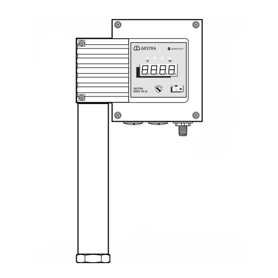
Page 36: Functional Elements Of The Nrgt 26-2 / Nrgt 26-2S
Terminal box Example Cover screws M4 x 16 mm NRGT 26-2 Operating panel with 4-digit LED display/malfunction and status LEDs and rotary knob, see page 43 M12 connector, 5-pole, A-coded NRGT 26-2, NRGT 26-2s - Installation & Operating Manual - 819876-00... -
Page 37: Electrical Connection
■ ■ Connecting the 24V DC power supply The NRGT 26-2 or NRGT 26-2s level transmitter is supplied with 24 V DC. ■ ■ A safety power supply unit that delivers a Safety Extra Low Voltage (SELV) and is isolated from con- ■... -
Page 38: Bringing Into Service
When the equipment is brought into service for the first time, the scale of the 0 – 100 % measuring range is factory-set to maximum for the electrode length used. After installation, set the measuring range to suitable values for your specific plant. NRGT 26-2, NRGT 26-2s - Installation & Operating Manual - 819876-00... - Page 39 Save your settings by pressing the rotary knob for approx. 1 second. The message “donE” is shown and the parameter appears on the display once more. NRGT 26-2, NRGT 26-2s - Installation & Operating Manual - 819876-00...
-
Page 40: Calibration At The Lower Limit Of The Active Measuring Range "Cal.l" (0 % Calibration Value)
Press and hold the rotary knob until the new value is displayed. Save your setting by pressing the rotary knob for approx. 1 second. Continue with calibration “CAL.P” or “CAL.H”. NRGT 26-2, NRGT 26-2s - Installation & Operating Manual - 819876-00... -
Page 41: Independent Rapid Calibration At A Water Level Of > 25 % Of The Active Measuring Range "Cal.p
Press and hold the rotary knob until the current time constant flashes on the display. Set the desired time constant (1 to 30 seconds). Save your setting by pressing the rotary knob for approx. 1 second. NRGT 26-2, NRGT 26-2s - Installation & Operating Manual - 819876-00... -
Page 42: Manually Initiating A Display Test
Never start up any plant that has not passed the above tests. ■ ■ NRGT 26-2 and NRGT 26-2s level transmitters may only be repaired by the manufacturer, ■ ■ GESTRA AG. Replace faulty equipment only with identical equipment from GESTRA AG. -
Page 43: Starting, Operation And Testing
Priority of fault code display Higher priority fault codes overwrite lower ones on the display! See page 47 ff. for fault indications and the fault code table. NRGT 26-2, NRGT 26-2s - Installation & Operating Manual - 819876-00... - Page 44 In the event of a malfunction or error state, an analogue value of 0 mA is displayed. ■ ■ Electrode malfunctions cannot be acknowledged. When a malfunction is corrected, the message disappears from the display, and the level transmitter returns to normal operation. NRGT 26-2, NRGT 26-2s - Installation & Operating Manual - 819876-00...
- Page 45 If the level transmitter does not behave as described above, the equipment may be faulty. ■ ■ Perform failure analysis. ■ ■ NRGT 26-2 and NRGT 26-2s level transmitters may only be repaired by the manufacturer, ■ ■ GESTRA AG. Only replace faulty equipment with identical equipment from GESTRA AG.
-
Page 46: System Malfunctions
Switch off the voltage to the system and secure so that it cannot be switched back on. ■ ■ Check that the system is not carrying live voltage before commencing work. ■ ■ NRGT 26-2, NRGT 26-2s - Installation & Operating Manual - 819876-00... -
Page 47: Indication Of System Malfunctions Using Fault Codes
PWMTSTCh1Err Replace the level transmitter measurement signal Channel 2 reading with disabled E.011 PWMTSTCh2Err Replace the level transmitter measurement signal E.012 FreqErr Measurement signal frequency Replace the level transmitter NRGT 26-2, NRGT 26-2s - Installation & Operating Manual - 819876-00... - Page 48 Generally speaking, electromagnetic interference can be the cause of virtually all of the fault codes mentioned above. It is more likely to be the cause of permanent faults; however, it should also be considered in the case of sporadic fault indications. NRGT 26-2, NRGT 26-2s - Installation & Operating Manual - 819876-00...
-
Page 49: Common Application And Usage Errors
The measuring range is incorrectly set. ■ ■ Inspect the electrode and protective tube for soiling and ■ ■ The electrode or protective tube is soiled. ■ ■ clean if necessary. NRGT 26-2, NRGT 26-2s - Installation & Operating Manual - 819876-00... - Page 50 If the temperature rises above 75 °, the fault terminal box, e.g. by providing cooling. code E.027 (Overtemp Err) appears and the 0 mA current output causes a fault shutoff. NRGT 26-2, NRGT 26-2s - Installation & Operating Manual - 819876-00...
-
Page 51: Checking Installation And Function
Also check that the level remains within the MIN and MAX limits when limit indicators are connected. ■ ■ Check the switchpoints when bringing into service and every time the NRGT 26-2 or NRGT 26-2s ■ ■ level transmitter is replaced. -
Page 52: Taking Out Of Service
Reduce the boiler pressure to 0 bar. Allow the level electrode to cool to room temperature. Switch off the supply voltage. Detach the plug-in connection. Next, remove the level electrode. NRGT 26-2, NRGT 26-2s - Installation & Operating Manual - 819876-00... -
Page 53: Cleaning The Measuring Electrode Of The Level Transmitter
GESTRA AG. Such media include solid, liquid or gaseous substances, mixtures of these, or radiation. GESTRA AG can accept returned products only if accompanied by a completed and signed return note, along with a completed and signed declaration of decontamination. -
Page 54: Eu Declaration Of Conformity
EU Declaration of Conformity We hereby declare that the NRGT 26-2 / NRGT 26-2s level transmitter conforms to the following European Directives: Directive 2014/68/EU EU Pressure Equipment Directive ■ ■ Directive 2014/35/EU Low Voltage Directive ■ ■ Directive 2014/30/EU EMC Directive ■... - Page 55 NRGT 26-2, NRGT 26-2s - Installation & Operating Manual - 819876-00...
- Page 56 You can find our authorised agents around the world at: www.gestra.com GESTRA AG Münchener Straße 77 28215 Bremen Germany Phone +49 421 3503-0 +49 421 3503-393 e-mail info@de.gestra.com www.gestra.com 819876-00/08-2019cm (808952-00) · GESTRA AG · Bremen · Printed in Germany...
Need help?
Do you have a question about the NRGT 26-2 and is the answer not in the manual?
Questions and answers