GESTRA LRG 16-4 Installation Instructions Manual
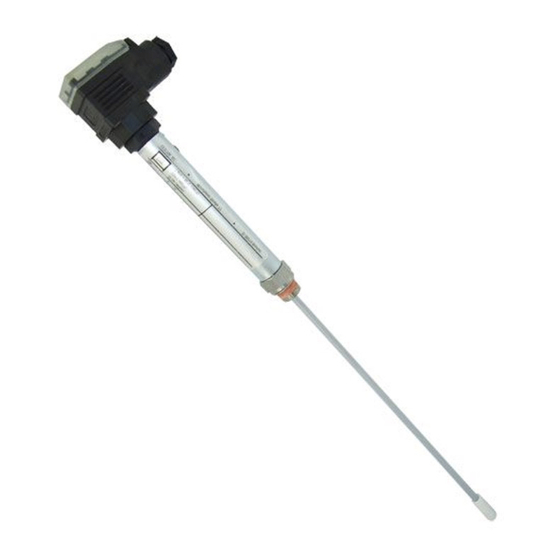
Conductivity electrode
Hide thumbs
Also See for LRG 16-4:
- Installation instructions manual (8 pages) ,
- Installation & operating manual (72 pages) ,
- Installation & operating manual (28 pages)

Related Manuals for GESTRA LRG 16-4


Summary of Contents for GESTRA LRG 16-4
- Page 1 GESTRA Steam Systems LRG 16-4 English Installation Instructions 818854-01 Conductivity Electrode LRG 16-4...
-
Page 2: Table Of Contents
Tools ...............................9 Examples of installation LRG 16-4 ..............................10 Key ...............................11 Electrical connection LRG 16-4 with four-pole connector .......................12 Key ...............................12 Tools ..............................12 Connecting the conductivity electrode ....................13 LRG 16-4, connecting the four-pole connector ..................13 Troubleshooting Indication, diagnosis and remedy ......................14... - Page 3 Contents - continued - Page Maintenance Safety note ............................15 Cleaning measuring electrode .......................15 Removing and disposing of the conductivity electrode Remove and discard conductivity electrode LRG 16-4................15...
-
Page 4: Important Notes
The equipment must only be used within the admissible pressure and temperature ratings. Function The conductivity electrode LRG 16-4 is used in combination with the following equipment as conductivity limiter and continuous blowdown controller in steam boilers: Conductivity switch LRS 1-50... -
Page 5: Safety Note
Important notes - continued - Safety note The equipment must only be installed, wired and commissioned by qualified and competent staff. Retrofitting and maintenance work must only be performed by qualified staff who - through adequate training - have achieved a recognised level of competence. Danger When loosening the conductivity electrode steam or hot water might escape! This presents the risk of severe scalding all over the body! -
Page 6: Directives And Standards
ATEX (Atmosphère Explosible) The conductivity electrode LRG 16-4 is a simple item of electrical equipment as specified in EN 60079-11 section 5.7. According to the European Directive 94/9/EC the equipment must be equipped with approved Zener barriers if used in potentially explosive areas. Applicable in Ex zones 1, 2 (1999/92/EC). -
Page 7: Technical Data
Type approval no. TÜV . WÜL . 12-017, 12-018 (see name plate) Scope of supply LRG 16-4 1 Conductivity electrode LRG 16-4 1 Joint ring 17 x 21, form D, DIN 7603, 1.4301, bright annealed 1 Installation manual Name plate / marking... -
Page 8: Installation
∅ 23 Screwed G A, ISO 228 ISO 228 Ra 3.2 Fig. 2 Fig. 3 LRG 16-4 with four-pole connector A B C 15 118 95 20 129 105 18 25 137 115 18 40 180 150 18 Fig. 4... -
Page 9: Mounting Conductivity Electrode
For the approval of the boiler standpipe the relevant regulations must be considered. Refer to pages 10 and 11 for typical installation examples. If installed outdoors the level electrode must be equipped with a GESTRA weather protection cover. Attention Install conductivity electrode horizontally or with a vertical inclination. -
Page 10: Examples Of Installation
Examples of installation LRG 16-4 Conductivity monitoring and continuous boiler blowdown, direct installation of conductivity electrode via T-type connector and connection of a continuous blowdown valve ~ 250 LRG 16-4 A, ISO 228 Fig. 5 R*: 40 mm Conductivity monitoring, direct installation of conductivity electrode via flanged standpipe on the side of the boiler or installation of electrode in an external level pot ≥... -
Page 11: Key
Examples of installation - continued - LRG 16-4 - continued - Conductivity monitoring and continuous boiler blowdown, installation of conductivity electrode in top blowdown line via separate level pot LRG 16-4 Fig. 7 Joint ring 17 x 21, form D, DIN 7603, 1.4301, bright annealed... -
Page 12: Electrical Connection
Electrical connection LRG 16-4 with four-pole connector Fig. 9 Fig. 8 Contact plate of conductivity electrode Screws M 4 Cable strain relief Cover Cable gland M 16 (PG 9) Upper part of terminal box Wiring of terminals Connecting plate Insulating plate... -
Page 13: Connecting The Conductivity Electrode
Max. cable length between conductivity electrode and controller: 30 m, with conductivities from 1 to 10 μS/cm: max. 10 m. LRG 16-4, connecting the four-pole connector 1. Loosen screws a. Fig. 8 2. Remove upper part c of the terminal box from the level electrode but leave insulating plate e on contact plate f. -
Page 14: Troubleshooting
Troubleshooting Indication, diagnosis and remedy Attention Before carrying out the fault diagnosis please check: Supply voltage: Is the conductivity switch / controller supplied with the mains voltage specified on the name plate? Wiring: Is the wiring in accordance with the wiring diagram? Malfunctions Conductivity switch / controller does not work accurately. - Page 15 Re-install the conductivity electrode. Observe the notes given in section "Installation" and "Electrical Connection". Removing and disposing of the conductivity electrode Remove and discard conductivity electrode LRG 16-4. 1. Loosen screw i . Fig. 22 2. Detach upper part of the terminal box k from the conductivity electrode.
- Page 16 P. O Box 10 54 60, D-28054 Bremen Münchener Str. 77, D-28215 Bremen Tel. 0049 (0) 421 / 35 03-0 0049 (0) 421 / 35 03-393 E-mail gestra.ag@flowserve.com www.gestra.com 818854-01/05-2013cm (808793-01) · GESTRA AG · Bremen · Printed in Germany...
Need help?
Do you have a question about the LRG 16-4 and is the answer not in the manual?
Questions and answers