Sign In
Upload
Manuals
Brands
GESTRA Manuals
Transmitter
NRGT 26-2s
User Manuals: GESTRA NRGT 26-2s Level Transmitter
Manuals and User Guides for GESTRA NRGT 26-2s Level Transmitter. We have
2
GESTRA NRGT 26-2s Level Transmitter manuals available for free PDF download: Original Installation & Operating Manual
GESTRA NRGT 26-2s Original Installation & Operating Manual (60 pages)
Level Transmitter
Brand:
GESTRA
| Category:
Transmitter
| Size: 0 MB
Table of Contents
Table of Contents
2
Content of this Manual
4
Scope of Delivery/Product Package
4
How to Use this Manual
5
Illustrations and Symbols Used
5
Hazard Symbols in this Manual
5
Types of Warning
6
Specialist Terms / Abbreviations
7
Usage for the Intended Purpose
8
Admissible System Components, Dependent on the Required Safety Integrity Level
8
Improper Use
9
Basic Safety Notes
9
Required Personnel Qualifications
10
Notes on Product Liability
10
Functional Safety, Safety Integrity Level (SIL)
11
Check the Secure Current Output Regularly
11
Reliability Data to en 61508
12
Function
13
Technical Data
15
Example Name Plate / Identification of the NRGT 26-2/NRGT 26-2S
18
Factory Settings
19
Overall View of the NRGT 26-2
20
Overall View of the NRGT 26-2S
21
Dimensions of the NRGT 26-2
22
Dimensions of the NRGT 26-2S
23
Preparing for Installation
24
Installation
25
Installing the NRGT 26-2
26
Sealing Surface Dimensions of the NRG 26-2
26
Example
26
Installing Two Level Electrodes in a Flange by Detaching a Terminal Box
27
Installing Two Level Electrodes in a Flange by Detaching a Terminal Box
28
Installing Two Level Electrodes in a Flange by Detaching a Terminal Box
29
Installing the NRGT 26-2S
29
Installation Example with Dimensions for the NRGT 26-2
30
Positioning the Terminal Box
35
Functional Elements of the NRGT 26-2 / NRGT 26-2S
36
Electrical Connection
37
Notes on Electrical Connection
37
Connecting the 24 V DC Power Supply
37
Connecting the Actual Value Output (4-20 Ma)
37
Pin Assignment of the M12 Connector for Non Pre-Wired Control Cables
37
Bringing into Service
38
Changing the Factory Settings if Necessary
38
Changing Parameters with Password Protection Enabled
38
Calibrate the Lower Limit of the Active Measuring Range "CAL.L" (0% Calibration Value)
41
Perform Independent Rapid Calibration at a Water Level of > 25% of the Active Measuring Range "CAL.P
41
Calibrate the Upper Limit of the Active Measuring Range "CAL.H" (100% Calibration Value)
42
Setting the Filter Constant "Filt
42
Manually Initiating a Display Test
42
Viewing the Software Version and Equipment Type "Info
43
Enabling/Disabling Password Protection
43
Checking the Level Display by Raising or Reducing the Level
44
Checking the Safety Function by Initiating a Test Function
44
Starting, Operation and Testing
45
System Malfunctions
48
Causes
48
Indication of System Malfunctions Using Error Codes
49
Common Application and Usage Errors
51
Checking Installation and Function
53
Taking out of Service/Disassembly
54
Cleaning the Measuring Electrode of the Level Transmitter
55
Cleaning Interval
55
Disposal
55
Returning Decontaminated Equipment
55
Declaration of Conformity; Standards and Directives
56
Advertisement
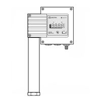
GESTRA NRGT 26-2s Original Installation & Operating Manual (56 pages)
Level Transmitter
Brand:
GESTRA
| Category:
Transmitter
| Size: 0 MB
Table of Contents
Table of Contents
2
Content of this Manual
4
Scope of Delivery/Product Package
4
How to Use this Manual
5
Illustrations and Symbols Used
5
Hazard Symbols in this Manual
5
Types of Warning
6
Specialist Terms/Abbreviations
7
Usage for the Intended Purpose
8
Applicable Directives and Standards
8
Admissible System Components, Dependent on the Required Safety Level
9
Improper Use
9
Basic Safety Notes
10
Required Personnel Qualifications
11
Notes on Product Liability
11
Functional Safety, Safety Integrity Level (SIL)
12
Check the Secure Current Output Regularly
12
Reliability Data to en 61508
13
Function
14
Technical Data
16
Name Plate/Identification of NRGT 26-2
19
Name Plate/Identification of NRGT 26-2S
20
Factory Settings
21
Overall View of the NRGT 26-2
22
Overall View of the NRGT 26-2S
23
Dimensions of the NRGT 26-2
24
Dimensions of the NRGT 26-2S
25
Preparing for Installation
26
Installation
27
Installing the NRGT 26-2
28
Sealing Surface Dimensions of the NRG 26-2
28
Example
28
Installing Two Level Electrodes in a Flange
29
Installing the NRGT 26-2S
29
Installation Example with Dimensions for the NRGT 26-2
30
Positioning the Terminal Box
35
Functional Elements of the NRGT 26-2 / NRGT 26-2S
36
Electrical Connection
37
Notes on Electrical Connection
37
Connecting the 24V DC Power Supply
37
Connecting the Actual Value Output (4 - 20 Ma)
37
Pin Assignment of the M12 Connector for Non Pre-Wired Control Cables
37
Bringing into Service
38
Changing the Factory Settings if Necessary
38
Calibration at the Lower Limit of the Active Measuring Range "CAL.L" (0 % Calibration Value)
40
Independent Rapid Calibration at a Water Level of > 25 % of the Active Measuring Range "CAL.P
41
Calibration at the Upper Limit of the Active Measuring Range "CAL.H" (100 % Calibration Value)
41
Setting the Filter Constant "Filt
41
Manually Initiating a Display Test
42
Checking the Level Display by Raising or Reducing the Level
42
Checking the Safety Function by Initiating a Test Function
42
Starting, Operation and Testing
43
System Malfunctions
46
Causes
46
Indication of System Malfunctions Using Fault Codes
47
Common Application and Usage Errors
49
Checking Installation and Function
51
Taking out of Service
52
Cleaning the Measuring Electrode of the Level Transmitter
53
Cleaning Interval
53
Disposal
53
Returning Decontaminated Equipment
53
EU Declaration of Conformity
54
Advertisement
Related Products
GESTRA NRGT 26-2n
GESTRA NRGT 26-2
GESTRA NRGT 26-1S
GESTRA NRGT 26-1
GESTRA LRG 16-4
GESTRA LRGT 16-3
GESTRA LRGT 16-3n
GESTRA LRGT 16-4
GESTRA LRGT 16-4n
GESTRA LRGT 17-3
GESTRA Categories
Switch
Controller
Control Unit
Measuring Instruments
Transmitter
More GESTRA Manuals
Login
Sign In
OR
Sign in with Facebook
Sign in with Google
Upload manual
Upload from disk
Upload from URL