GESTRA LRGT 16-3 Original Installation & Operating Manual
Conductivity transmitter
Hide thumbs
Also See for LRGT 16-3:
- Installation & operating manual (56 pages) ,
- Installation & operating manual (72 pages) ,
- Installation & operating manual (64 pages)

Subscribe to Our Youtube Channel
Related Manuals for GESTRA LRGT 16-3


Summary of Contents for GESTRA LRGT 16-3
- Page 1 Conductivity Transmitter LRGT 16-3 LRGT 16-4 LRGT 17-3 Original Installation & EN (USA) Operating Manual 850689-00 English...
-
Page 2: Table Of Contents
Overall view ............................20 LRGT 16-3 ............................ 20 LRGT 16-4 ............................ 20 LRGT 17-3 ............................ 20 Dimensions of the LRGT 16-3......................22 Dimensions of the LRGT 16-4......................23 Dimensions of the LRGT 17-3......................24 Preparing for installation ......................... 25 Installation ............................26 Montage ............................. - Page 3 Contents s ........................33 Functional element Electrical connection .......................... 34 Notes on electrical connection ....................... 34 Connecting the 24 V DC power supply ................... 34 Connecting the actual value output (4 - 20 mA)................34 Pin assignment of the M12 connector for non pre-wired control cables ......... 34 Bringing into service ..........................
-
Page 4: Content Of This Manual
1 x Conductivity transmitter LRGT 1x-x ■ 1 x Installation & Operating Manual ■ Required accessories for LRGT 16-3, LRGT 17-3 and LRGT 16-4 when installing for the first time 1 cable jack Binder series 713 99-0436-58-05 ■ LRGT 1x-x - USA - Installation & Operating Manual - 850689-00... -
Page 5: How To Use This Manual
How to use this Manual This Installation & Operating Manual describes the correct use of LRGT 16-3, LRGT 16-4 and LRGT 17-3 conductivity transmitters, abbreviated below as LRGT 1x-x. It applies to persons who inte- grate this equipment in control systems, install, bring into service, operate, maintain and dispose of this equipment. -
Page 6: Types Of Warning
Types of warning DANGER Warning of a dangerous situation that results in death or serious injury. WARNING Warning of a dangerous situation that may possibly result in death or serious injury. CAUTION Warning of a situation that may result in minor or moderate injury. ATTENTION Warning of a situation that results in damage to property or the environment. -
Page 7: Specialist Terms, Abbreviations
Here, we explain some abbreviations, specialist terms, etc., which are used in this Manual. LRGT .. / LRR .. / URS .. / URB .. / SRL .. / etc. Equipment and type designations of GESTRA AG. SELV Safety Extra Low Voltage... -
Page 8: Usage For The Intended Purpose
Usage for the intended purpose LRGT 16-3, LRGT 16-4 and LRGT 17-3 conductivity transmitters can be used as conductivity limiters and blowdown controllers to continually measure conductivity in steam boilers and hot water installations. They present a linear profile of conductivity in a preset measuring range via a 4 - 20 mA current output. -
Page 9: Admissible System Components
Manuals for the system components used. You can find the latest Installation & Operating Manuals for other system components ■ on our website: http://www.gestra.com Improper use There is a danger of death due to explosion if the equipment is used in potentially explosive atmospheres. -
Page 10: Basic Safety Information
Attempts to repair the equipment will cause the plant to become unsafe. LRGT 1x-x conductivity electrodes may only be repaired by the manufacturer, ■ GESTRA AG. Only replace faulty equipment with identical equipment from GESTRA AG. ■ LRGT 1x-x - USA - Installation & Operating Manual - 850689-00... -
Page 11: Required Personnel Qualifications
Basic safety information A lack of proper maintenance and cleaning can result in damage to the conductivi- ty electrode and/or false measurement results and warnings. Once a year, check the conductivity electrode by performing reference ■ measurements. If the “CF” (cell constant) value of 003.0 is exceeded after recalibra- tion, the warning code “CF.Hi”... -
Page 12: Function
4 - 20 mA current signal. Measuring process of the LRGT 16-3 and LRGT 17-3 LRGT 16-3 and LRGT 17-3 conductivity transmitters use the conductometric two-electrode measuring process. A measuring current with a suitable frequency for the measuring range is introduced into the fluid. - Page 13 Function Indicators and signals, see page 43 / 47 * LRGT 1x-x conductivity transmitters feature a green 4-digit, 7-segment display for showing read- ings, status information and error codes. The operating status is indicated by one red and three green LEDs. Behavior when switched on * The display alternately shows the software version, the type and then the measured conductivity.
-
Page 14: Technical Data
Technical data Design and mechanical connection LRGT 16-3, LRGT 16-4, LRGT 17-3 Thread 1" - 11.5 NPT, see Fig. 7, 8 and 9 ■ Nominal pressure rating, admissible service pressure and temperature LRGT 16-3 464 psi at 460 °F (32 bar at 238 °C) ■... - Page 15 * Resolution for internal processing based on 15 bits with plus or minus sign (16 bits). The above figures refer to the uncompensated conductivity. Time constant “T” (measured using the two-bath process) Temperature Conductivity LRGT 16-3, LRGT 17-3 9 seconds 14 seconds ■ LRGT 16-4...
- Page 16 -40 °F – 158 °F (-40 °C – 80 °C) ■ Air humidity: 10% – 95%, non-condensing ■ Weight LRGT 16-3, LRGT 16-4, LRGT 17-3 approx. 4.63 lb (2.1 kg) ■ Other information Independently mounted Type 1 action operating control ■ Pollution degree 2, impulse voltage 330 V ■...
-
Page 17: Rating Plate, Identification
Rating plate, identification Safety Betriebsanleitung note beachten See installation instructions Voir instructions de montage Equipment designation LRGT 16-3 Leitfähigkeitstransmitter Equipment function Conductivity Transmitter Transmetteur de mesure Nominal pressure rating, de conductibilité connection thread, Protection 1-11,5NPT 1.4404/F316L IP65 material of screw-in body... - Page 18 Tamb 0,25-3000ppm 0,5-6000µS/cm 25-5000ppm 50-10000µS/cm ± ± OUT: 4-20mA / 500W OUT: 4-20mA / 500W GESTRA AG GESTRA AG Münchener Str. 77 Münchener Str. 77 28215 Bremen 28215 Bremen Made in Germany Made in Germany Input voltage: 24VDC Input power: 7W...
-
Page 19: Default Factory Settings
Default factory settings LRGT 1x-x conductivity transmitters are delivered ex works with the following settings: Parameter values Parameter Menu display Unit LRGT 16-3 LRGT 16-4 LRGT 17-3 Cell constant 0.210 Temperature coefficient % / °C 002.1 Filter constant (damping) FiLt... -
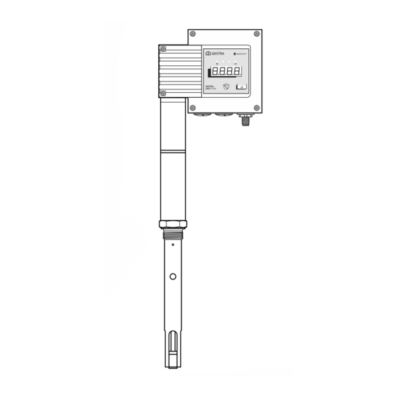
Page 20: Overall View
Overall view LRGT 16-3 LRGT 16-4 µS µS LRGT 17-3 Fig. 6 LRGT 1x-x - USA - Installation & Operating Manual - 850689-00... - Page 21 M12 connector, 5-pole, A-coded Cover tube Electrode thread Threaded pin M2.5 mm (LRGT 16-3, LRGT 17-3) Measuring tube with measuring electrode (LRGT 16-3, LRGT 17-3), measuring electrodes (LRGT 16-4) Spacer LRGT 1x-x - USA - Installation & Operating Manual - 850689-00...
-
Page 22: Dimensions Of The Lrgt 16-3
Dimensions of the LRGT 16-3 6.9 in (175 mm) µS w = 2.76 in (70 mm) Thermal insulation Size 41 provided on site 1" - 11.5 NPT x = available electrode lengths: 7.87 in (200 mm) ■ 11.81 in (300 mm) ■... -
Page 23: Dimensions Of The Lrgt 16-4
Dimensions of the LRGT 16-4 6.9 in (175 mm) w = 2.76 in (70 mm) Thermal insulation Size 41 provided on site 1" - 11.5 NPT x = available electrode lengths: 7.08 in (180 mm) ■ 11.81 in (300 mm) ■... -
Page 24: Dimensions Of The Lrgt 17-3
Dimensions of the LRGT 17-3 6.9 in (175 mm) µS w = 2.76 in (70 mm) Thermal insulation provided on site Size 41 1" - 11.5 NPT x = available electrode lengths: 7.87 in (200 mm) ■ 11.81 in (300 mm) ■... -
Page 25: Preparing For Installation
Preparing for installation If the equipment is to be installed outdoors, outside the protection of a building, environmental influences may adversely affect function. Pay attention to the permitted ambient conditions in the technical data, ■ see page 16. Do not operate the equipment if the temperature is below freezing. ■... -
Page 26: Installation
Installation DANGER Danger to life from scalding! Hot steam may escape abruptly. Hot steam or hot water can escape suddenly if the conductivity electrode is unscrewed while under pressure. Reduce the boiler pressure to 0 psi (0 bar) and check the pressure before unscrewing ■... -
Page 27: Montage
False measurement results are a risk to plant safety. Therefore, always adhere to the distances stated below. LRGT 16-3, LRGT 17-3 Leave a distance of approx. 1.18 in (30 mm) between the lower end of the measuring ■... -
Page 28: Installing The Lrgt 1X-X
Montage Installing the LRGT 1x-x Make sure that the internal and external threads are in perfect condition. ■ Do not apply more than three windings of PTFE insulating tape around the electrode thread. ■ WARNING Do not use too much tape. Do not use fitting lubricants or pastes. Fit the electrode and tighten first with your hand and then with a size 41 open-ended wrench. -
Page 29: Installation Examples With Dimensions
13.35 in (338 mm) ~9.85 in (~250 mm) 1" - 11.5 NPT e.g., LRGT 16-3 * Minimum distances (R) LRGT 16-3 / LRGT 17-3 R = 1.20 in (30 mm) ■ LRGT 16-4 R = 2.4 in (60 mm) ■... -
Page 30: Conductivity Monitoring And Continuous Blowdown Control
~7.90 in ~9.85 in (~250 mm) (~197 mm) 1" - 11.5 NPT e.g., LRGT 16-3 * Minimum distances (R): LRGT 16-3 / LRGT 17-3 R = 1.2 in (30 mm) ■ LRGT 16-4 R = 2.4 in (60 mm) ■... -
Page 31: Conductivity Monitoring And Continuous Blowdown Control Via A Separate Level Pot
Key, see page 32 Outlet DN 15 - 40 1" - 11.5 NPT Inlet DN 15 - 40 e.g., LRGT 16-3 Fig. 14 All lengths and diameters in inches (mm) LRGT 1x-x - USA - Installation & Operating Manual - 850689-00... -
Page 32: Aligning The Terminal Box
Installation examples with dimensions Key, Fig. 1012 to Fig. 1214 Boiler drum Shut-off valve GAV Continuous blowdown valve BAE T-type connector Level pot Aligning the terminal box If necessary, you can orientate the display in the desired direction by rotating the terminal box. ATTENTION Rotating the terminal box ≥... -
Page 33: Functional Element S
Functional element Fig. 15 Terminal box Operating panel with 4-digit LCD, malfunction and status LEDs and rotary knob, see page 43 M12 connector, 5-pole, A-coded Use a shielded, multi-core TC-ER control cable with minimum wire size AWG 18, e.g., ÖLFLEX CONTROL TM CY 5G1. LRGT 1x-x - USA - Installation &... -
Page 34: Electrical Connection
CONTROL TM CY 5G1. Connecting the 24 V DC power supply LRGT 16-3, LRGT 17-3 and LRGT 16-4 conductivity transmitters are supplied with 24 V DC. ■ A safety power supply unit that delivers a Safety Extra Low Voltage (SELV / PELV / CLASS2) and ■... -
Page 35: Bringing Into Service
Bringing into service Before bringing into service, check that the conductivity transmitter is correctly connected. ■ Then switch on the supply voltage. ■ Change the default settings if necessary You will need the following tools Flat blade screwdriver, size 3/32 in (2.4 mm) ■... - Page 36 Bringing into service Selecting and setting a parameter: Using a screwdriver, turn the rotary knob clockwise or counterclockwise until the desired parameter appears on the display. The set value is displayed after approx. 3 seconds. The display alternates between the set parameter and its actual value, e.g., Filt.
- Page 37 If numbers or decimal points are displayed incorrectly or not at all, you must replace ■ the conductivity transmitter with an identical one from GESTRA AG. Manually initiate a display test. Alternatively, initiate the display test by selecting “diSP”, see page 41.
-
Page 38: Changing The Cell Constant
Bringing into service Changing the cell constant Notes on calibrating the cell constant The cell constant of LRGT 1x-x conductivity transmitters is precisely set at the factory. If recalibra- tion is necessary at the installation site due to the conditions there, (see page 42, comparing the reading with a reference reading), you can change the cell constant on site. -
Page 39: Changing The Temperature Coefficient
Bringing into service Changing the temperature coefficient You can adjust the temperature coefficient manually, as long as an appropriate value has been established. The factory setting of “2.1” is normally used for steam generating units with constant pressure. For newly installed electrodes, this figure may need to be adapted in line with the temperature coefficient of the boiler water. -
Page 40: Using The "Filt" Feature
Bringing into service Using the “FiLt” feature The aim of this feature is to “smooth” the 4 - 20 mA actual value output of the conduc- tivity transmitter for use on the controller. The adjustable time constant (1 - 30 seconds) influences both the current output ■... -
Page 41: Changing The Display Unit (Μs/Cm Or Ppm)
Faulty equipment is a danger to plant safety. If numbers or decimal points are displayed incorrectly or not at all, you must replace ■ the conductivity transmitter with an identical one from GESTRA AG. LRGT 1x-x - USA - Installation & Operating Manual - 850689-00... -
Page 42: Comparing The Reading With The Reference Reading From A Reliable Sample
Also see the description of parameter “tC” on page 39. LRGT 1x-x conductivity transmitters may only be repaired by the manufacturer, ■ GESTRA AG. Only replace faulty equipment with identical equipment from GESTRA AG. ■ LRGT 1x-x - USA - Installation & Operating Manual - 850689-00... -
Page 43: Starting, Operation And Testing
Starting, operation and testing Fig. 17 Operating panel: Display of actual value/error code/limit value - green, 4 digits LED 1, error, red LED 3, µS/cm, green LED 4, ppm, green LED 2, function OK, green Rotary knob/button for operation and settings Priority of the various error codes Errors are displayed based on their priority. - Page 44 Starting, operation and testing Cross-reference of the display and LEDs and the operating state of the conductivity transmitter: Starting All LEDs light up - Test The system is started and tested. The LEDs and display are tested. Display: S-xx = software version Switch on the t-09 = equipment type supply voltage...
- Page 45 Perform failure analysis. ■ LRGT 1x-x conductivity transmitters may only be repaired by the manufacturer, ■ GESTRA AG. Only replace faulty equipment with identical equipment from GESTRA AG. ■ LRGT 1x-x - USA - Installation & Operating Manual - 850689-00...
-
Page 46: System Malfunctions
System malfunctions Causes System malfunctions occur as the result of incorrect installation, overheated equipment, interfer- ence in the supply network, or faulty electronic components. Check the installation and configuration before systematic troubleshooting Installation: Check that the installation location complies with the permitted ambient conditions in terms of ■... -
Page 47: Display Of System Malfunctions Using Error Codes
System malfunctions Display of system malfunctions using error codes Fig. 18 Display of actual value/error code/limit value - green, 4 digits Error code table Error Internal Possible errors Corrective action code designation LFKurzschlussErr Short circuit in conductivity mea- E.001 Replace conductivity transmitter (CondShortCircuitErr) surement (electrode wires) Check installation location. - Page 48 System malfunctions Error code table 16-bit AD converter E.014 ADSReadErr Replace conductivity transmitter not responding E.015 UnCalibErr Calibration invalid Replace conductivity transmitter Second shutdown path of E.017 ENDRVErr Replace conductivity transmitter 4 - 20 mA analog output faulty System voltage -12 V outside E.018 V12NegErr Replace conductivity transmitter...
-
Page 49: Faults That Do Not Provoke A Shutdown
Has the electrode been correctly insulated to prevent ■ leakage? Replace the conductivity transmitter with an identical ■ unit from GESTRA AG. The inner seals of the electrode rods Replace the conductivity transmitter with an identical ■ are damaged. unit from GESTRA AG. -
Page 50: Checking Installation And Function
System malfunctions Checking installation and function When you have corrected system malfunctions, perform a function test as follows. Check installation and function. ■ Check the indicated reading and perform an equipment test, see page 45, when bringing ■ into service and whenever an LRGT 1x-x conductivity transmitter has been replaced. System malfunctions in LRGT 1x-x conductivity transmitters produce an output of 0 mA at the analog output. -
Page 51: Taking Out Of Service, Removal
Taking out of service, removal DANGER Danger to life from scalding! Hot steam may escape abruptly. Hot steam or hot water can escape suddenly if the conductivity electrode is unscrewed while under pressure. Reduce the boiler pressure to 0 psi (0 bar) and check the pressure before unscrewing ■... -
Page 52: Cleaning The Measuring Electrodes Of The Conductivity Transmitter
Scrub off stubborn deposits using sandpaper (medium grain). Continue as described below: = key to overall view, see page 21 LRGT 16-3, LRGT 17-3, LRGT 16-4 Install the clean conductivity transmitter as described on pages 25 - 28. Switch on the supply voltage. -
Page 53: Disposal
The term ‘media’ can refer to solid, liquid or gaseous substances or mixtures, as well as radiation. GESTRA AG can accept returned products only if accompanied by a completed and signed return note and also a completed and signed declaration of decontamination. - Page 54 You can find our authorized agents around the world at: www.gestra.com GESTRA AG Münchener Straße 77 28215 Bremen Germany Tel. +49 421 3503 0 +49 421 3503 393 e-mail info@de.gestra.com www.gestra.com 850689-00/08-2021cm (809121-00) · GESTRA AG · Bremen...
Need help?
Do you have a question about the LRGT 16-3 and is the answer not in the manual?
Questions and answers