GESTRA NRGT 26-2 Original Installation & Operating Manual
Level transmitter
Hide thumbs
Also See for NRGT 26-2:
- Original installation & operating manual (56 pages) ,
- Original installation & operating manual (52 pages) ,
- Original installation & operating manual (60 pages)

Subscribe to Our Youtube Channel
Related Manuals for GESTRA NRGT 26-2


Summary of Contents for GESTRA NRGT 26-2
- Page 1 Level Transmitter NRGT 26-2 Original Installation & Operating EN (USA) Manual 850688-00 English...
-
Page 2: Table Of Contents
Preparing for installation ........................21 Installation ............................22 Installing the NRGT 26-2 ........................ 23 Example of installation with dimensional specification for NRGT 26-2 ........... 24 Aligning the terminal box ........................25 Functional elements of the NRGT 26-2 ....................26 Electrical connection .......................... 27 Notes on electrical connection ....................... - Page 3 Taking out of service .......................... 42 Cleaning the electrode of the level transmitter ................. 43 Cleaning interval ..........................43 Disposal .............................. 43 Returning decontaminated equipment ....................43 UL Listed components ........................43 NRGT 26-2 - USA - Installation & Operating Manual - 850688-00...
-
Page 4: Content Of This Manual
1 Level transmitter NRGT 26-2 ■ 1 Installation & Operating Manual ■ Required accessories for NRGT 26-2 when installing for the first time 1 Cable jack Binder series 713 99-0436-58-05 ■ NRGT 26-2 - USA - Installation & Operating Manual - 850688-00... -
Page 5: How To Use This Manual
How to use this Manual This Installation & Operating Manual describes the correct use of the NRGT 26-2 level transmitter. It applies to persons who integrate this equipment in control systems, install, bring into service, op- erate, maintain and dispose of this equipment. Anyone carrying out the above-mentioned activities must have read this Installation &... -
Page 6: Types Of Warning
Warning of a dangerous situation that may possibly result in death or serious injury. CAUTION Warning of a situation that may result in minor or moderate injury. ATTENTION Warning of a situation that results in damage to property or the environment. NRGT 26-2 - USA - Installation & Operating Manual - 850688-00... -
Page 7: Specialist Terms / Abbreviations
A boiler that is operated at 145 psi (10 bar) and 356°F (180°C) may be designed to withstand a pressure of 870 psi (60 bar) and a temperature of 527°F (275°C), for example, which is therefore not necessarily its operating point. NRGT 26-2 - USA - Installation & Operating Manual - 850688-00... -
Page 8: Usage For The Intended Purpose
The NRGT 26-2 level transmitter can be used to continually measure the water level in steam boiler and hot-water plants, or in condensate and feedwater tanks. The calibrated measuring range from 0% to 100% constitutes the linear profile of the 4-20 mA current output. The NRGT 26-2 is classified as operating control in accordance with UL60730-1. -
Page 9: Permitted System Components
Usage for the intended purpose Permitted system components According to UL60730-2-15, the NRGT 26-2 level electrode can be regarded as an operating con- trol, which delivers the measured water level via the 4-20 mA output. Any electronic control unit with an input for a 4-20 mA unit signal can be connected and used for analysis. -
Page 10: Basic Safety Information
Check that the plant is not carrying live voltage before commencing work. ■ Danger to life from a faulty NRGT 26-2 level electrode due to the sudden escape of hot steam or hot water. Shocks and impacts during transport or installation can result in damage to or leaks in the level electrode, causing pressurized hot steam or hot water to escape through the pressure relief hole. -
Page 11: Required Personnel Qualifications
Persons trained by the plant operator to work Refits Specialist staff with pressure and temperature. Fig. 1 Notes on product liability The manufacturer cannot accept any liability for damages resulting from improper use of the equipment. NRGT 26-2 - USA - Installation & Operating Manual - 850688-00... -
Page 12: Function
A protective tube installed on the system ensures reliable function. They can also be installed in an external level pot that communicates with the boiler. A capacitive NRGT 26-2 level transmitter can be installed in the same protective tube or level pot as a conductive NRG 1x-50 or NRG 1x-51 level electrode. - Page 13 If necessary, you can adapt the electrode parameters to suit conditions at the plant. You can set parameters and change default settings using a rotary knob on the terminal box, see page 29. NRGT 26-2 - USA - Installation & Operating Manual - 850688-00...
-
Page 14: Technical Data
51.20 inch 55.10 inch 59.05 inch 78.75 inch range: (1000 mm) (1100 mm) (1200 mm) (1300 mm) (1400 mm) (1500 mm) (2000 mm) Do not shorten the electrode rod. NRGT 26-2 - USA - Installation & Operating Manual - 850688-00... - Page 15 NEMA type 3R, 3RX and 5 ■ IP 65 to EN 60529 ■ Other information Independently mounted Type 1 action operating control ■ Pollution degree 2, impulse voltage 330 V ■ NRGT 26-2 - USA - Installation & Operating Manual - 850688-00...
- Page 16 Maximum inclination of 45°. In this case, the length of the electrode rod is limited ■ to maximum 27.1 inch (688 mm) A protective tube [NPS 2 (DN 50)] is required for internal installation ■ NRGT 26-2 - USA - Installation & Operating Manual - 850688-00...
-
Page 17: Name Plate/Identification Of The Nrgt 26-2
Output rating: 4-20mA Environmental rating: NEMA Type 3R / 3RX / 5 OPERATING CONTROL E513189 Fig. 2 The date of production is stamped on the screw-in body of the level transmitter. NRGT 26-2 - USA - Installation & Operating Manual - 850688-00... -
Page 18: Factory Settings
Factory settings The NRGT 26-2 level transmitter is delivered ex works with the following settings. Menu display Parameter values Unit Raw value (hex) CAL.L Variable approx. 50 mV CAL.P Variable Raw value (hex) Raw value (hex) CAL.H Variable 100% approx. 2.0 V... -
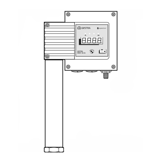
Page 19: Overall View Of The Nrgt 26-2
Operating panel with 4-digit LED display/ error and status LEDs and rotary knob, see page 33 M12 connector, 5-pole, A-coded Cover tube (simplified view) Electrode thread Electrode Electrode rod insulation, PTFE Fig. 4 NRGT 26-2 - USA - Installation & Operating Manual - 850688-00... -
Page 20: Dimensions Of The Nrgt 26-2
60.20 inch (1528 mm) 55.10 inch (1400 mm) Fig. 5 All lengths and diameters in inches 64.45 inch (1636 mm) 59.05 inch (1500 mm) (mm) 84.90 inch (2156 mm) 78.75 inch (2000 mm) NRGT 26-2 - USA - Installation & Operating Manual - 850688-00... -
Page 21: Preparing For Installation
Take further measures to protect the equipment from lightning, insects and animals, ■ and salty air. You will need the following tools: NRGT 26-2 Size 41 open-ended wrench, see page 20. ■ NRGT 26-2 - USA - Installation & Operating Manual - 850688-00... -
Page 22: Installation
For internal installation, check the boiler standpipe and flange during the preliminary ■ boiler inspection. If the NRGT 26-2 is to be installed obliquely, the maximum inclination of the level ■ electrode is 45°, and the length of the electrode rod is then limited to maximum 27.1 inch (688 mm). -
Page 23: Installing The Nrgt 26-2
(The band grounding clamp is available as an optional accessory) Next, measure the resistance again. The value must be < 10 ohms and entered as followed: Measured resistance: __________________________ ohms Boiler wall Visible thread Fig. 6 NRGT 26-2 - USA - Installation & Operating Manual - 850688-00... -
Page 24: Example Of Installation With Dimensional Specification For Nrgt 26-2
Level pot for external use. Illustration not to scale. Key, see page 25 ¾" - 14 NPT ≥ ≥ 1.05" ( 26 mm) Fig. 7 All lengths and diameters in inches (mm) NRGT 26-2 - USA - Installation & Operating Manual - 850688-00... -
Page 25: Aligning The Terminal Box
If necessary, you can orientate the display in the desired direction by rotating the terminal box. ATTENTION Rotating the terminal box ≥ 180° will damage the internal wiring of the NRGT 26-2 level transmitter. Never rotate the terminal box more than 180 degrees in either direction. -
Page 26: Functional Elements Of The Nrgt 26-2
33 M12 connector, 5-pole, A-coded Use a shielded, multi-core TC-ER control cable with minimum wire size AWG 18, e.g., OELFLEX CONTROL TM CY 5G1. Fig. 7 NRGT 26-2 - USA - Installation & Operating Manual - 850688-00... -
Page 27: Electrical Connection
If non pre-wired control cables are used, you must wire the cable to match the pin assignment of the M12 connector. Shield +24 V Power supply -0 V Power supply +20 mA Data line -20 mA Data line Fig. 9 Connector NRGT 26-2 - USA - Installation & Operating Manual - 850688-00... -
Page 28: Bringing Into Service
Transmitter must be connected to a 4 - 20 mA load on the output (if not, error message E.013 is shown). Error message E.001 is indicated if electrode is exposed. NRGT 26-2 - USA - Installation & Operating Manual - 850688-00... - Page 29 (“quit”) and the old parameter value is retained. Save your settings by pressing the rotary knob for approx. 1 second. The message “donE” is shown and the parameter appears on the display once more. NRGT 26-2 - USA - Installation & Operating Manual - 850688-00...
-
Page 30: Calibration To The Lower Limit Of The Active Measuring Range "Cal.l" (0% Calibration Value)
Press and hold the rotary knob until the new value is displayed. Save your settings by pressing the rotary knob for approx. 1 second. Continue with calibration “CAL.P” or “CAL.H”. NRGT 26-2 - USA - Installation & Operating Manual - 850688-00... -
Page 31: Independent Rapid Calibration At A Water Level Of > 25% Of The Active Measuring Range "Cal.p
Press and hold the rotary knob until the current time constant flashes on the display. Set the desired time constant (1 to 30 seconds). Save your settings by pressing the rotary knob for approx. 1 second. NRGT 26-2 - USA - Installation & Operating Manual - 850688-00... -
Page 32: Manually Initiating A Display Test
Never start up any plant that has not passed the above tests. ■ The NRGT 26-2 level transmitter may only be repaired by the manufacturer, GESTRA AG. ■ Only replace faulty equipment with identical equipment from GESTRA AG. -
Page 33: Starting, Operation And Testing
Priority of error code display Higher-priority error codes overwrite lower-priority ones on the display! See page 37 ff. for indications based on the error code table. NRGT 26-2 - USA - Installation & Operating Manual - 850688-00... - Page 34 In the event of a malfunction or error state, an analog value of 0 mA is output. ■ Electrode malfunctions are acknowledged automatically When a malfunction is corrected, the indication also disappears from the display and the level transmitter returns to normal operation. NRGT 26-2 - USA - Installation & Operating Manual - 850688-00...
- Page 35 ■ faulty. Perform failure analysis. ■ The NRGT 26-2 level transmitter may only be repaired by the manufacturer, GESTRA AG. ■ Only replace faulty equipment with identical equipment from GESTRA AG. ■ NRGT 26-2 - USA - Installation & Operating Manual - 850688-00...
-
Page 36: System Malfunctions
Switch off the voltage to the plant and secure so that it cannot be switched back on. ■ Check that the plant is not carrying live voltage before commencing work. ■ NRGT 26-2 - USA - Installation & Operating Manual - 850688-00... -
Page 37: Indication Of System Malfunctions Using Error Codes
Channel 1 reading with disabled E.010 PWMTSTCh1Err Replace level transmitter measurement signal Channel 2 reading with disabled E.011 PWMTSTCh2Err Replace level transmitter measurement signal E.012 FreqErr Measurement signal frequency Replace level transmitter NRGT 26-2 - USA - Installation & Operating Manual - 850688-00... - Page 38 Virtually all of the aforementioned error codes can be caused by electromagnetic inter- ference. This is less likely to be the case in the event of permanent errors, but should be considered for sporadic error indications. NRGT 26-2 - USA - Installation & Operating Manual - 850688-00...
-
Page 39: Common Application And Usage Errors
Calibrate the measuring range at the operating point. ■ ■ The electrode or level pot/protective tube Inspect the electrode and level pot/protective tube for ■ ■ is soiled. soiling and clean if necessary. NRGT 26-2 - USA - Installation & Operating Manual - 850688-00... - Page 40 Reduce the ambient temperature around the terminal ■ If the temperature rises above 167°F (75°C), box, e.g., by cooling. the error code E.027 (Overtemp Err) appears and the 0 mA current output causes a fault shutdown. NRGT 26-2 - USA - Installation & Operating Manual - 850688-00...
-
Page 41: Checking Installation And Function
Also check that the level remains within the MIN and MAX limits when limit indicators are ■ connected. Check the switchpoints when bringing into service and every time the NRGT 26-2 level trans- ■ mitter is replaced. System malfunctions in the NRGT 26-2 level transmitter result in an output of 0 mA at the analog output. -
Page 42: Taking Out Of Service
Reduce the boiler pressure to 0 psi (0 bar). Allow the level electrode to cool to room temperature. Switch off the supply voltage. Pull out the connector. Then remove the level electrode. NRGT 26-2 - USA - Installation & Operating Manual - 850688-00... -
Page 43: Cleaning The Electrode Of The Level Transmitter
The term ‘media’ can refer to solid, liquid or gaseous substances or mixtures, as well as radiation. GESTRA AG can accept returned products only if accompanied by a completed and signed return note and also a completed and signed declaration of decontamination. - Page 44 You can find our authorized agents around the world at: GESTRA AG Münchener Strasse 77 28215 Bremen Germany Phone +49 421 3503-0 +49 421 3503-393 e-mail info@de.gestra.com www.gestra.com 850688-00/06-2021cm (809120-00) · GESTRA AG · Bremen...
Need help?
Do you have a question about the NRGT 26-2 and is the answer not in the manual?
Questions and answers