GESTRA LRGT 16-3 Installation & Operating Manual
Conductivity transmitter
Hide thumbs
Also See for LRGT 16-3:
- Installation & operating manual (56 pages) ,
- Installation & operating manual (72 pages) ,
- Original installation & operating manual (54 pages)

Subscribe to Our Youtube Channel
Related Manuals for GESTRA LRGT 16-3


Summary of Contents for GESTRA LRGT 16-3
- Page 1 Conductivity Transmitter LRGT 16-3 LRGT 16-4 LRGT 17-3 Installation & Operating Manual 819877-01 E n g l i s h...
-
Page 2: Table Of Contents
Overall view ..............................20 LRGT 16-3 ............................... 20 LRGT 16-4 ............................... 20 LRGT 17-3 ............................... 20 Dimensions of the LRGT 16-3........................22 Dimensions of the LRGT 16-4........................23 Dimensions of the LRGT 17-3........................24 Installation ..............................25 Additional notes for installation ........................ 26 Example, LRGT 16-3 .......................... - Page 3 Contents s ..........................35 Functional element Electrical connection ............................ 36 Notes on electrical connection ......................... 36 Connecting the 24 V DC power supply ..................... 36 Connecting the actual value output (4-20 mA)..................36 Pin assignment of the M12 connector for non pre-wired control cables ........... 36 Bringing into service ............................
-
Page 4: Content Of This Manual
■ 1 x Installation & Operating Manual ■ Required accessories for LRGT 16-3, LRGT 17-3 and LRGT 16-4 when installing for the first time Connecting cable, M12 A-coded, 5m, mat. no. 1508392 ■ Connecting cable, M12 A-coded, 10m, mat. no. 1508394 ■... -
Page 5: How To Use This Manual
How to use this Manual This Installation & Operating Manual describes how to correctly use LRGT 16-3, LRGT 16-4 and LRGT 17-3 conductivity transmitters. It applies to all persons who integrate this equipment into control systems, install, bring into service, operate, maintain and dispose of this equipment. Anyone carrying out the above-mentioned activities must have read this Installation &... -
Page 6: Types Of Warning
Types of warning DANGER Warning of a dangerous situation that will result in death or serious injury. WARNING Warning of a dangerous situation that may possibly result in death or serious injury. CAUTION CAUTION Warning of a situation that may result in minor or moderate injury. ATTENTION Warning of a situation that will result in damage to property or the environment. -
Page 7: Specialist Terms/Abbreviations
International standard IEC 61508 forms the basis for establishing, testing and operating technical safety systems. LRGT .. / LRR .. / URS .. / URB .. / SRL .. / etc. Equipment and type designations of GESTRA AG. SELV Safety Extra Low Voltage... -
Page 8: Usage For The Intended Purpose
Usage for the intended purpose LRGT 16-3, LRGT 16-4 and LRGT 17-3 conductivity transmitters can be used as conductivity limiters and continuous blowdown controllers to continually monitor conductivity in steam boilers and hot water installations. They present a linear profile of conductivity in a preset measuring range via a 4-20 mA current output. -
Page 9: Improper Use
When bringing the conductivity electrode into service, check that it is not leaking. ■ Attempts to repair the equipment will cause the plant to become unsafe. The LRGT 1x-x conductivity electrode may only be repaired by the manufacturer, GESTRA AG. ■ Only replace faulty equipment with identical equipment from GESTRA AG. -
Page 10: Required Personnel Qualifications
Basic safety notes A lack of proper maintenance and cleaning can result in damage to the conductivity electrode and/or false measurement results and warning messages. Check the conductivity electrode once a year by performing comparative measurements. If ■ the “CF” (cell constant) value of 003.0 is exceeded after recalibration, the warning message “CF.Hi”... -
Page 11: Functional Safety, Safety Integrity Level (Sil)
4-20 mA output, the entire event chain system can be operated at this safety integrity level. When combined with the accessories, you will have a type B subsystem in accordance with IEC 61508. The technical and safety characteristics in Fig. 2 below are based solely on LRGT 16-3, LRGT 16-4 and LRGT 17-3 conductivity transmitters. -
Page 12: Reliability Data To En 61508
Reliability data to EN 61508 Description Characteristic values Type of electrode LRGT 1x-3 LRGT 16-4 Safety integrity level SIL 2 SIL 2 Architecture 1oo1 1oo1 Type of equipment Type B Type B Hardware fault tolerance HFT = 0 HFT = 0 Overall failure rate for dangerous undetected λ... -
Page 13: Function
4-20 mA current signal. Measuring process of the LRGT 16-3 and LRGT 17-3 LRGT 16-3 and LRGT 17-3 conductivity transmitters use the conductometric two-electrode measuring process. A measuring current with a suitable frequency for the measuring range is introduced into the fluid. - Page 14 Electrode faults cannot be acknowledged. When the fault is corrected, the indication also disappears from the display, and the LRGT 16-3, LRGT 17-3 or LRGT 16-4-conductivity transmitter returns to normal operation. Behaviour when performing the test function * Initiating the test function by pressing the rotary knob on the LRGT 1x-x causes the maximum output cur- rent of 20 mA to be output.
-
Page 15: Technical Data
Technical data Model and mechanical connection LRGT 16-3, LRGT 16-4, LRGT 17-3 Thread G1 A, EN ISO 228-1, see Fig. 6, 8 and 9 ■ Nominal pressure rating, admissible service pressure and temperature LRGT 16-3 PN 40 32 bar (abs) at 238 °C ■... - Page 16 * Resolution for internal processing based on 15 bits with plus or minus sign (16 bits). The above figures refer to the uncompensated conductivity. Time constant “T” (measured using the two-bath process) Temperature Conductivity LRGT 16-3, LRGT 17-3 9 seconds 14 seconds ■ LRGT 16-4...
- Page 17 - 40 °C – 80 °C ■ Transport temperature: - 40 °C – 80 °C ■ Air humidity: 10% – 95%, non-condensing ■ Weight LRGT 16-3, LRGT 16-4, LRGT 17-3 approx. 2.1 kg ■ LRGT 1x-x - Installation & Operating Manual - 819877-01...
-
Page 18: Example Name Plate/Identification
Type-approval number Conformity marking Disposal information & Manufacturer Protection class Material number-serial number GESTRA AG Münchener Str.77 28215 Bremen Made in Germany Fig. 3 The date of production (quarter and year) is stamped on the screw-in body of each conductivity transmitter. -
Page 19: Factory Settings
Factory settings LRGT 1x-x conductivity transmitters are delivered ex works with the following settings: Parameter values Parameter Display in menu Unit LRGT 16-3 LRGT 16-4 LRGT 17-3 Cell constant 0.210 Temperature coefficient % / °C 002.1 Filter constant (damping) FiLt... -
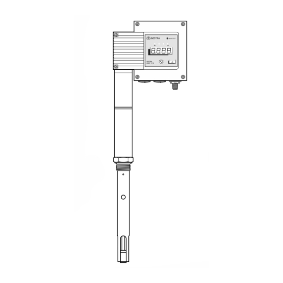
Page 20: Overall View
Overall view LRGT 16-3 LRGT 16-4 LRGT 17-3 Fig. 5 LRGT 1x-x - Installation & Operating Manual - 819877-01... - Page 21 Sealing ring D 33 x 39, form D, DIN 7603-2.4068, bright annealed Electrode thread Threaded pin M2.5 mm (LRGT 16-3, LRGT 17-3) Measuring tube with measuring electrode (LRGT 16-3, LRGT 17-3), measuring electrodes (LRGT 16-4) Spacer disc LRGT 1x-x - Installation & Operating Manual - 819877-01...
-
Page 22: Dimensions Of The Lrgt 16-3
Dimensions of the LRGT 16-3 w = 70 Size 41 Thermal insulation provided at the site x = available electrode lengths: 200 mm ■ 300 mm ■ 400 mm ■ 500 mm ■ 600 mm ■ 800 mm ■ 1000 mm ■... -
Page 23: Dimensions Of The Lrgt 16-4
Dimensions of the LRGT 16-4 w = 70 Size 41 Thermal insulation provided at the site x = available electrode lengths: 180 mm ■ 300 mm ■ 380 mm ■ 500 mm ■ 600 mm ■ 800 mm ■ 1000 mm ■... -
Page 24: Dimensions Of The Lrgt 17-3
Dimensions of the LRGT 17-3 w = 70 Size 41 Thermal insulation provided at the site x = available electrode lengths: 200 mm ■ 300 mm ■ 400 mm ■ 500 mm ■ 600 mm ■ 800 mm ■ 1000 mm ■... -
Page 25: Installation
Installation If the equipment is to be installed outdoors, outside the protection of a building, environ- mental influences may adversely affect function. Pay attention to the admissible ambient conditions in the technical data, ■ see page 17. Do not operate the equipment if the temperature is below freezing. ■... -
Page 26: Additional Notes For Installation
False measurement results are a risk to plant safety. Therefore, always adhere to the distances stated below. LRGT 16-3, LRGT 17-3 Provide spacing of approx. 30 mm between the lower end of the measuring tube and the ■... -
Page 27: Example, Lrgt 16-3
Installation Sealing surface dimensions for Inspect the sealing surfaces of the tank stand- LRGT 16-3, LRGT 16-4, LRGT 17-3 pipe or flange cover. Sealing surfaces must be perfectly machined, Ø 40 mm as shown in Fig. 9. Ra 3.2 Fig. 9... -
Page 28: Detaching The Terminal Box From The Electrode
Screw the conductivity electrode into the tank standpipe or flange cover, and tighten securely using a torque wrench (with size 41 open-ended spanner attachment). Tightening torque when cold: LRGT 16-3, LRGT 16-4, LRGT 17-3 = 250 Nm ■ Installation examples with dimensions, see Fig. 12, Fig. 13, Fig. 14 on page ... 31 Detaching the terminal box from the electrode When installing or removing the conductivity electrode (e.g. - Page 29 Installation Detaching the terminal box from the electrode You will need the following tools: Size 1 slotted screwdriver ■ Size 19 open-ended spanner ■ Undo and remove the rear panel of the terminal box opposite the operating unit. Interior view of terminal box: Do not twist or damage the connecting cables of the electrode.
- Page 30 Installation Detaching the terminal box from the electrode During cleaning/maintenance (see page 58) or taking out of service (see page 57) Unscrew the conductivity electrode from the tank standpipe. When installing for the first time or after cleaning/maintenance Screw the conductivity electrode into the tank standpipe. To do so, proceed as described on pages 27 / 28 (points 1.
-
Page 31: Installation Examples With Dimensions
Key, see page 34 ~ 250 Sealing ring D 33 x e.g. LRGT 16-3 39 DIN 7603-2.4068, bright annealed * Minimum distances (R) LRGT 16-3 / LRGT 17-3 R = 30 mm ■ LRGT 16-4 R = 60 mm ■ Fig. 12 All lengths and diameters in mm LRGT 1x-x - Installation &... -
Page 32: Conductivity Measurement And Continuous Blowdown Control
LRGT 16-3 Sealing ring D 33 x 39 DIN 7603-2.4068, bright annealed * Minimum distances (R): Distance (A), depending on connection flange: LRGT 16-3 / LRGT 17-3 R = 30 mm DN 15 mm A = 182 mm ■ ■... -
Page 33: Conductivity Measurement And Continuous Blowdown Control Via A Separate Level Pot
Outlet DN 15 - 40 Inlet DN 15 - 40 Sealing ring D 33 x 39 e.g. LRGT 16-3 DIN 7603-2.4068, bright annealed Fig. 14 All lengths and diameters in mm LRGT 1x-x - Installation & Operating Manual - 819877-01... -
Page 34: Key Fig. 12 To Fig. 14
Installation examples with dimensions Key Fig. 12 to Fig. 14 Boiler drum Stop valve GAV Continuous blowdown valve BAE T-type connector Level pot Aligning the terminal box If necessary, you can orientate the display in the desired direction by rotating the terminal box. ATTENTION Rotating the terminal box ≥... -
Page 35: Functional Element S
Functional element Fig. 15 Terminal box Cover screws M4 x 16 mm Operating panel with 4-digit LCD/malfunction and status LEDs and rotary knob, see page 48 M12 connector, 5-pole, A-coded LRGT 1x-x - Installation & Operating Manual - 819877-01... -
Page 36: Electrical Connection
Connecting the 24 V DC power supply LRGT 16-3, LRGT 17-3 and LRGT 16-4 conductivity transmitters are supplied with 24 V DC. ■ A safety power supply unit that delivers a Safety Extra Low Voltage (SELV) and is isolated from con- ■... -
Page 37: Bringing Into Service
Bringing into service Before bringing into service, check that the conductivity transmitter is correctly connected. ■ Next, switch on the supply voltage. ■ Changing the factory settings if necessary You will need the following tools Size 2.5 slotted screwdriver ■ Notes on bringing into service for the first time When the equipment is brought into service for the first time, the scale of the current output is set to 500 µS = 20 mA for the LRGT 1x-3 and 7000 µS = 20 mA for the LRGT 16-4. - Page 38 Bringing into service Selecting and setting a parameter: Using the screwdriver, turn the rotary knob clockwise or anti-clockwise until the desired parameter appears on the display. The set value is displayed after approx. 3 seconds. The display alternates between the set parameter and its actual value, e.g.
- Page 39 Bringing into service Without password entry: Set the desired value. reduce/increase the value Each parameter has an individual, admissible value range. By pressing the knob briefly, you can skip to the next digit. This is a more convenient way of making large changes to values. If you do not set a parameter within 10 seconds, the process is aborted (“quit”) and the old parameter value is retained.
- Page 40 If numbers or decimal points are displayed incorrectly or not at all, you must replace the ■ conductivity transmitter with an identical one from GESTRA AG. Manually initiating a display test. Alternatively, initiate the display test by pressing “diSP”, see page 45.
-
Page 41: Changing The Cell Constant
Bringing into service Changing the cell constant Notes on calibrating the cell constant The cell constant of the LRGT 1x-x conductivity transmitter is precisely set at the factory. If recalibration is necessary at the installation site due to the conditions there, (see page 47, comparing the reading with a reference reading), you may change the cell constant on site. -
Page 42: Changing The Temperature Coefficient
Bringing into service Changing the temperature coefficient You can adjust the temperature coefficient of the monitored fluid manually, as long as an appropriate value has been established. The factory setting of “2.1” is normally used for steam generating units with a constant pressure. -
Page 43: Using The "Filt" Feature
Bringing into service Using the “FiLt” feature The aim of this feature is to “smooth” the 4-20 mA actual value output of the conductivity transmitter for use on the controller. The adjustable time constant (1-30 seconds) influences both the current output and the ■... - Page 44 Bringing into service Measuring ranges of the LRGT 1x-3 based on the setting of the “Sout” parameter Conductivity measuring ranges/ Measuring ranges Current output actual value output (μS/cm at 25 °C) (mA = µS/cm) Adjustable via the rotary knob on 4 mA 20 mA the operating panel.
-
Page 45: Changing The Display Unit (Μs/Cm Or Ppm)
Faulty equipment jeopardises plant safety. If numbers or decimal points are displayed incorrectly or not at all, you must replace the ■ conductivity transmitter with an identical one from GESTRA AG. LRGT 1x-x - Installation & Operating Manual - 819877-01... -
Page 46: Viewing The Signal Reserve "Sgnl" (For Lrgt 16-4 Only)
Bringing into service Viewing the signal reserve “SGnL” (for LRGT 16-4 only) Pay attention to the setting instructions on page 38 and proceed as follows: Select the parameter “SGnL”. The signal quality is shown in 0-100%. This continually decreases as the electrode tips become more soiled. -
Page 47: Comparing The Reading With The Reference Measurement Of A Reliable Sample
Also see the description of parameter “tC” on page 42. LRGT 1x-x conductivity transmitters may only be repaired by the manufacturer, GESTRA AG. ■ Only replace faulty equipment with identical equipment from GESTRA AG. -
Page 48: Starting, Operation And Testing
Starting, operation and testing Fig. 19 The operating panel: Actual value display/error code/limit value, green, 4 digits LED 1, fault, red LED 3, unit µS/cm, green LED 4, unit ppm, green LED 2, function OK, green Rotary knob/pushbutton for operation and settings Notes on the priority of the various indications Fault indications are displayed based on their priority. - Page 49 Starting, operation and testing Relationship between display and LEDs and the operating state of the conductivity transmitter: Starting All LEDs light up - Test The system is started and tested. The LEDs and display are tested. Indication: S-xx = software version Switch on t-09 = equipment type supply voltage...
- Page 50 ■ faulty. Perform failure analysis. ■ LRGT 1x-x conductivity transmitters may only be repaired by the manufacturer, GESTRA AG. ■ Only replace faulty equipment with identical equipment from GESTRA AG. ■ LRGT 1x-x - Installation & Operating Manual - 819877-01...
-
Page 51: System Malfunctions
System malfunctions Causes System malfunctions occur as the result of incorrect installation, overheating of equipment, radiated interference to the supply network, or faulty electronic components. Check the installation and configuration before systematic troubleshooting Installation: Check that the installation location complies with the admissible ambient conditions in terms of ■... -
Page 52: Indication Of System Malfunctions Using Error Codes
System malfunctions Indication of system malfunctions using error codes Fig. 20 Actual value display/error code/limit value, green, 4 digits Error code table Internal Error code Possible errors Remedy designation Check the installation location. Have the minimum distances been adhered to? Short circuit in conductivity E.001 LFKurzschlussErr... - Page 53 System malfunctions Error code table Internal Error code Possible errors Remedy designation Test signal measuring voltage E.007 USIGTSTErr Replace the conductivity transmitter outside tolerance Test signal measuring current E.008 ISIGTSTErr Replace the conductivity transmitter outside tolerance Pt1000 test measuring voltage E.009 ADCTSTErr Replace the conductivity transmitter...
- Page 54 System malfunctions Error code table Internal Error code Possible errors Remedy designation System voltage 12 V outside E.023 V12Err Replace the conductivity transmitter limits Communication error (not LRGT Check the baud rate, wiring and terminating E.024 CANErr models) resistors E.025 ESMG1Err µC error Replace the conductivity transmitter...
-
Page 55: Faults That Do Not Provoke A Shutdown
Has the electrode been correctly insulated to prevent ■ leakage? Replace the conductivity transmitter with an identical ■ unit from GESTRA AG. The inner seals of the electrode rods Replace the conductivity transmitter with an identical ■ are damaged. unit from GESTRA AG. -
Page 56: Checking Installation And Function
System malfunctions The code “SG.Lo” flashes on the display Possible causes if no error codes are shown Remedy Remove the conductivity transmitter, ■ see page 57 The measurement signal is low and below the defined Check and clean the electrode, see page 58 ■... -
Page 57: Taking Out Of Service/Disassembly
Taking out of service/Disassembly DANGER Danger to life from scalding caused by the sudden escape of hot steam. Hot steam or water can escape suddenly if the conductivity electrode is unscrewed under pressure. Reduce the boiler pressure to 0 bar and check the pressure before you unscrew the ■... -
Page 58: Cleaning The Measuring Electrodes Of The Conductivity Transmitter
Scrub off stubborn deposits using sandpaper (medium grain). Move on to the points below: = key to overall view, see page 21 LRGT 16-3, LRGT 17-3, LRGT 16-4 Fit the clean conductivity transmitter as described on page 25. Switch on the supply voltage. -
Page 59: Disposal
GESTRA AG. Such media include solid, liquid or gaseous substances, mixtures of these, or radiation. GESTRA AG can accept returned products only if accompanied by a completed and signed return note and also a completed and signed declaration of decontamination. -
Page 60: Declaration Of Conformity; Standards And Directives
You can find details on the conformity of the equipment and the applicable standards and directives in the Declaration of Conformity and associated certificates. You can download the Declaration of Conformity from www.gestra.com and request relevant certificates by writing to the following address: GESTRA AG Münchener Straße 77... - Page 61 For your notes LRGT 1x-x - Installation & Operating Manual - 819877-01...
- Page 62 For your notes LRGT 1x-61 - Installation & Operating Manual - 819877-01...
- Page 63 For your notes LRGT 1x-61 - Installation & Operating Manual - 819877-01...
- Page 64 Tel. +49 421 3503 0 Unit 1 Sopwith Park, Royce Close, +49 421 3503 393 West Portway Business Park, Andover, e-mail info@de.gestra.com Hampshire SP10 3TS Website www.gestra.com United Kingdom 819877-01/10-2022cm (808953-01) · GESTRA AG · Bremen · Printed in Germany...
Need help?
Do you have a question about the LRGT 16-3 and is the answer not in the manual?
Questions and answers