Table of Contents
Advertisement
REVISION B
Form No. 3308250.020 09/16
(French 33108310.022_B)
©2016 Dometic Corporation
LaGrange, IN 46761
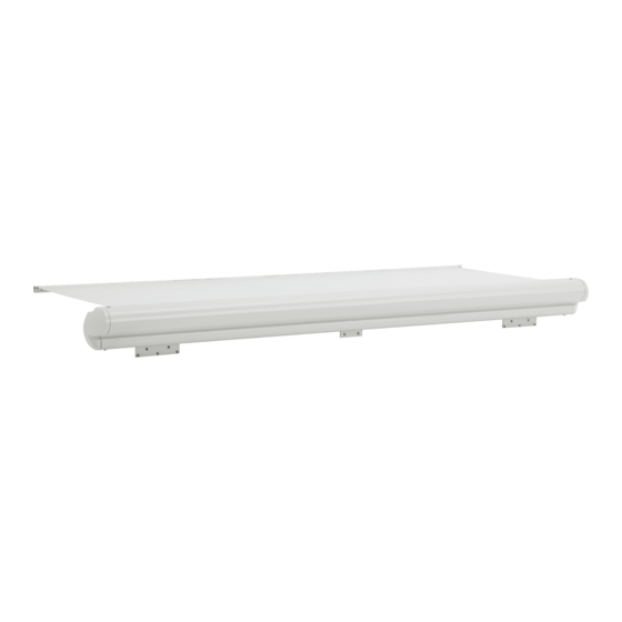
ELITE SLIDE TOPPER
SLIDE OUT ROOM AWNING
WITH FULL COVER
Read these instructions carefully. These
instructions MUST stay with this product.
USA
SERVICE OFFICE
Dometic Corporation
1120 North Main Street
Elkhart, IN 46514
RECORD THIS INFORMATION FOR FUTURE
REFERENCE:
FRTA Model Number
FRTA Serial Number
Hardware Model Number
Hardware Serial Number
Date Purchased
Retailer / Qualified Installer
86196(XX).(XXX)-(X)
86200(XX).(XXX)-(X)
86202(XX).(XXX)-(X)
86300(XX).(XXX)-(X)
CANADA
Dometic Corporation
46 Zatonski, Unit 3
Brantford, ON N3T 5L8
CANADA
SERVICE CENTER &
DEALER LOCATIONS
Please Visit:
www.eDometic.com
Advertisement
Table of Contents

Summary of Contents for Dometic ELITE SLIDE TOPPER Series
- Page 1 SERVICE CENTER & Form No. 3308250.020 09/16 DEALER LOCATIONS SERVICE OFFICE Dometic Corporation (French 33108310.022_B) Dometic Corporation 46 Zatonski, Unit 3 Please Visit: ©2016 Dometic Corporation 1120 North Main Street Brantford, ON N3T 5L8 www.eDometic.com LaGrange, IN 46761 Elkhart, IN 46514 CANADA...
-
Page 2: Table Of Contents
Use these instructions to ensure correct installation, function, and operation of product. Dometic Corporation reserves the right to modify appearances and specifications without notice. TABLE OF CONTENTS INTRODUCTION ..................................2 DOCUMENT SYMBOLS ................................2... -
Page 3: Important Safety Instructions
● Do NOT add any devices or accessories to this Understand Signal Words product except those specifically authorized in writing by Dometic Corporation. A signal word will identify safety messages and ● Frequently examine product for imbalance (un- property damage messages, and will indicate the even fit / sagging / loose parts);... -
Page 4: General Information
GENERAL INFORMATION Bracket Options Optional Components & Kits One of the following Slide Topper bracket options is 3107940.003 Mounting Bracket Spacer Kit required (not included): 3308176.001 Edge Protector (10 Pack) 3308176.019 Edge Protector (100 Pack) 3106992.062# 45º Wall Bracket Kit with 15″ 3309526.170# Cradle Kit Hex Extension... - Page 5 SPECIFICATIONS SLIDE OUT RECOMMENDED SLIDE OUT RECOMMENDED ROOM WIDTH AWNING LENGTH ROOM WIDTH AWNING LENGTH 50″ to 55-3/4″ SEE NOTE 1 308″ to 313-3/4″ 318″ 56″ to 61-3/4″ 66″ 314″ to 319-3/4″ 324″ 62″ to 67-3/4″ 72″ 320″ to 325-3/4″ 330″...
-
Page 6: Mounting Bracket Selection
SPECIFICATIONS Mounting Bracket Selection 1. Determine mounting bracket type. See (FIG. 2) & (FIG. 3). See available bracket kits under "A. Bracket Options" on page (4). Mounting brackets may be installed on slide out room flange ONLY if it provides solid structural support. FIG. -
Page 7: Mounting Bracket Spacer (Optional)
SPECIFICATIONS Mounting Bracket Spacer (Optional) 2. Determine mounting bracket location relating to awning rail and slide out room flange. See If slide out room flange has special features (large (FIG. 2), (FIG. 3), (FIG. 4) & (FIG. 5). curve, recessed into RV wall, etc.) that will interfere ... -
Page 8: Installation
INSTALLATION Prepare Slide Topper Installation Instructions 1. D etermine awning rail location relating to mount- The Slide Topper requires minor preparation before installing on RV. ing bracket & slide out room flange. See (FIG. 2) & (FIG. 3). 1. C arefully lay fabric roller tube assembly (FRTA) on a clean, well padded “V”... - Page 9 INSTALLATION 10. Slide the pre-mounted hex extension rod into FIG. 10 #10-32 X 1/2″ Quadrex Trilob Screw one of the previously mounted wall mounting brackets on slide out room as the fabric is in- stalled into awning rail. See (FIG. 12) FIG.
- Page 10 INSTALLATION FIG. 14 FIG. 16 Awning Rail Cover Contact Contact Point Point Cotter Pin Wall #10-32 #10-32 Mounting X 1/2″ X 1/2″ Bracket Self Self Tapping Tapping Wall Mounting Bracket #10-16 X .63″ PHCR Screws Screw Screw 15. Move one torsion bracket until cover touches FIG.
- Page 11 INSTALLATION III. Pull to stretch opposite edge of awning FIG. 18 Cover fabric approximately 3/4″, and secure with #6 X 7/16″ TEK screw through awning rail (approximately 2″ from fabric edge). Pinch Pinch Point Point FIG. 19 #6 X 7/16″ TEK Screw Awning Rail 2″...
-
Page 12: Operation
S ee "B. Optional Components & Kits" on Bracket page (4) to order Dometic edge protec- tors. Spacer A Dometic edge protector may NOT be com- patible with all applications. If a Dometic edge protector cannot be used, a similar type (compatible) edge protector MUST be installed. -
Page 13: General Use And Care
A pply a very small dab of VLP (Vinyl Liquid Patch) on tip of cotton swab. 1. Do NOT use strong chemicals or abrasives to clean parts, as their protective sur- V LP is available from Dometic Cor- faces will be damaged. poration. Reference...


Need help?
Do you have a question about the ELITE SLIDE TOPPER Series and is the answer not in the manual?
Questions and answers